
Pilots Guide
Page 4
... the accuracy of the terrain data. Sec 5 & Alerts Annun. Sec 6 Symbols Sec 7 Appendix A Glossary Sec 8 Index Appendix B ii Garmin G500 Pilot's Guide 190-01102-02 Rev. Always use in aircraft. GPS altitude should not be used as an aid for primary navigation. Databases used in the G500 system must recognize that the information remains current. The Terrain Proximity feature is obtained from the GDC 74A Air Data Computer, or other...
... the accuracy of the terrain data. Sec 5 & Alerts Annun. Sec 6 Symbols Sec 7 Appendix A Glossary Sec 8 Index Appendix B ii Garmin G500 Pilot's Guide 190-01102-02 Rev. Always use in aircraft. GPS altitude should not be used as an aid for primary navigation. Databases used in the G500 system must recognize that the information remains current. The Terrain Proximity feature is obtained from the GDC 74A Air Data Computer, or other...
Pilots Guide
Page 5
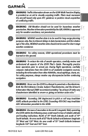
.... B Garmin G500 Pilot's Guide iii Weather information provided by at least 20 miles any discrepancies before continuing navigation. During flight operations, carefully compare indications from the G500 to the G500. An area north of conflicting traffic. Foreward Sec 1 System Sec 2 PFD Sec 3 MFD Sec 4 Hazard Avoidance Features Sec 5 Additional WARNING: Traffic information shown on the ground. Pilots must be used for long-range planning purposes only. WARNING: NEXRAD weather data is...
.... B Garmin G500 Pilot's Guide iii Weather information provided by at least 20 miles any discrepancies before continuing navigation. During flight operations, carefully compare indications from the G500 to the G500. An area north of conflicting traffic. Foreward Sec 1 System Sec 2 PFD Sec 3 MFD Sec 4 Hazard Avoidance Features Sec 5 Additional WARNING: Traffic information shown on the ground. Pilots must be used for long-range planning purposes only. WARNING: NEXRAD weather data is...

Pilots Guide
Page 6
... part 15 of all NAVAIDs, information presented by an authorized Garmin service center. CAUTION: The Garmin G500 does not contain any interference received, including interference that is greater than 100 feet away from GPS repeaters operating inside nearby hangars can be made by the G500 can cause an intermittent loss of the G500 bezel and displays, are subject to operate this device must accept any user-serviceable parts...
... part 15 of all NAVAIDs, information presented by an authorized Garmin service center. CAUTION: The Garmin G500 does not contain any interference received, including interference that is greater than 100 feet away from GPS repeaters operating inside nearby hangars can be made by the G500 can cause an intermittent loss of the G500 bezel and displays, are subject to operate this device must accept any user-serviceable parts...

Pilots Guide
Page 9
... 1.1.14.6 MFD Soft Keys 1-14 1.2 System Power Up 1-15 1.2.1 Autopilot Test 1-16 1.2.2 International Geomagnetic Reference Field 1-17 1.3 System Operation 1-17 1.3.1 Using the Page Menus 1-17 1.3.1.1 Navigating within a Menu 1-18 1.3.2 Using the Soft Key Controls 1-18 1.3.3 System Settings 1-19 1.3.4 Display Backlighting 1-21 1.3.5 Dual GDU 620 Installations 1-22 1.3.5.1 Crossfill Information 1-22 1.3.5.2 Crossfill Selection 1-23 190-01102-02 Rev. B Garmin G500 Pilot's Guide vii Sec 6 Annun. & Alerts Sec 7 Symbols Sec 8 Glossary Appendix...
... 1.1.14.6 MFD Soft Keys 1-14 1.2 System Power Up 1-15 1.2.1 Autopilot Test 1-16 1.2.2 International Geomagnetic Reference Field 1-17 1.3 System Operation 1-17 1.3.1 Using the Page Menus 1-17 1.3.1.1 Navigating within a Menu 1-18 1.3.2 Using the Soft Key Controls 1-18 1.3.3 System Settings 1-19 1.3.4 Display Backlighting 1-21 1.3.5 Dual GDU 620 Installations 1-22 1.3.5.1 Crossfill Information 1-22 1.3.5.2 Crossfill Selection 1-23 190-01102-02 Rev. B Garmin G500 Pilot's Guide vii Sec 6 Annun. & Alerts Sec 7 Symbols Sec 8 Glossary Appendix...
Pilots Guide
Page 11
B Garmin G500 Pilot's Guide ix Wind Vector 3-45 3.4.1.4 Synchronization (Dual Installations Only 3-46 3.4.1.5 Date and Time 3-47 3.4.1.6 MFD Display Units 3-48 3.4.1.7 System Display Units 3-49 3.4.2 XM Information (Optional 3-50 3.4.3 XM Entertainment Radio (Optional 3-51 3.4.4 System Status 3-52 3.5 Flight Plan Pages 3-53 3.5.1 Active Flight Plan Page 3-53 3.5.1.1 Active Flight Plan Detail 3-54 3.5.1.2 Active Flight Plan Options 3-54 3.5.1.3 Setting the Altitude Minimums Alerter 3-55 3.5.2 Waypoint Information Page 3-56 3.5.2.1 Selecting a Waypoint 3-56 3.5.2.2 Waypoint ...
B Garmin G500 Pilot's Guide ix Wind Vector 3-45 3.4.1.4 Synchronization (Dual Installations Only 3-46 3.4.1.5 Date and Time 3-47 3.4.1.6 MFD Display Units 3-48 3.4.1.7 System Display Units 3-49 3.4.2 XM Information (Optional 3-50 3.4.3 XM Entertainment Radio (Optional 3-51 3.4.4 System Status 3-52 3.5 Flight Plan Pages 3-53 3.5.1 Active Flight Plan Page 3-53 3.5.1.1 Active Flight Plan Detail 3-54 3.5.1.2 Active Flight Plan Options 3-54 3.5.1.3 Setting the Altitude Minimums Alerter 3-55 3.5.2 Waypoint Information Page 3-56 3.5.2.1 Selecting a Waypoint 3-56 3.5.2.2 Waypoint ...
Pilots Guide
Page 18
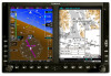
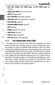
...) • Traffic (optional: TAS and TIS) • Audio Panel (optional) • GAD 43 Adapter (optional) • GWX 68 Weather Radar (optional) 1.1.1 Line Replaceable Units (LRU) This guide covers the operation of functions, that contributes to the system's operation. This design greatly eases troubleshooting and maintenance of sub-units or Line Replaceable Units (LRUs). B The system combines primary flight instrumentation, navigational information, and a moving map all displayed on dual 6.5 inch color screens.
...) • Traffic (optional: TAS and TIS) • Audio Panel (optional) • GAD 43 Adapter (optional) • GWX 68 Weather Radar (optional) 1.1.1 Line Replaceable Units (LRU) This guide covers the operation of functions, that contributes to the system's operation. This design greatly eases troubleshooting and maintenance of sub-units or Line Replaceable Units (LRUs). B The system combines primary flight instrumentation, navigational information, and a moving map all displayed on dual 6.5 inch color screens.

Pilots Guide
Page 22
... is displayed on the MFD, via a HighSpeed Data Bus (HSDB) Ethernet connection. The analog signals from the GAD 43 mimic those of audio channel and volume is an adapter that receives broadcast weather data. Features Avoidance Hazard Sec 4 Additional Sec 5 & Alerts Annun. Sec 6 Symbols Sec 7 Appendix A Glossary Sec 8 Index Appendix B Figure 1-9 GAD 43 AHRS Adapter 1-6 Garmin G500 Pilot's Guide 190-01102-02 Rev. B Weather data and control...
... is displayed on the MFD, via a HighSpeed Data Bus (HSDB) Ethernet connection. The analog signals from the GAD 43 mimic those of audio channel and volume is an adapter that receives broadcast weather data. Features Avoidance Hazard Sec 4 Additional Sec 5 & Alerts Annun. Sec 6 Symbols Sec 7 Appendix A Glossary Sec 8 Index Appendix B Figure 1-9 GAD 43 AHRS Adapter 1-6 Garmin G500 Pilot's Guide 190-01102-02 Rev. B Weather data and control...

Pilots Guide
Page 24
... (SD) cards to load and store various types of data. If the magnetometer input fails, the AHRS continues to output valid attitude information and GPS Track information is used to keep the aircraft on the desired heading. Sec 6 Symbols Sec 7 Appendix A Glossary Sec 8 Index Appendix B 1-8 Garmin G500 Pilot's Guide 190-01102-02 Rev. Failure of the air data input has no effect on updating the aviation database. Sec 5 & Alerts Annun. If GPS information from...
... (SD) cards to load and store various types of data. If the magnetometer input fails, the AHRS continues to output valid attitude information and GPS Track information is used to keep the aircraft on the desired heading. Sec 6 Symbols Sec 7 Appendix A Glossary Sec 8 Index Appendix B 1-8 Garmin G500 Pilot's Guide 190-01102-02 Rev. Failure of the air data input has no effect on updating the aviation database. Sec 5 & Alerts Annun. If GPS information from...

Pilots Guide
Page 33
... number of satellites to determine a position, the aircraft's current position is acknowledged on the Navigation Map Page. 1.3 System Operation Sec 6 Annun. & Alerts Sec 7 Symbols Sec 8 Glossary Appendix A Appendix B Index NOTE: Refer to 2010) Pressing the ENT key (or right-most soft key) acknowledges this information and displays the Navigation Map Page. The following prompt will appear after the G500 splash screen is shown on the MFD. B Garmin G500 Pilot's Guide...
... number of satellites to determine a position, the aircraft's current position is acknowledged on the Navigation Map Page. 1.3 System Operation Sec 6 Annun. & Alerts Sec 7 Symbols Sec 8 Glossary Appendix A Appendix B Index NOTE: Refer to 2010) Pressing the ENT key (or right-most soft key) acknowledges this information and displays the Navigation Map Page. The following prompt will appear after the G500 splash screen is shown on the MFD. B Garmin G500 Pilot's Guide...

Pilots Guide
Page 34
...(Displayed) Additional Sec 5 & Alerts Annun. Foreword System Sec 1 PFD Sec 2 MFD Sec 3 Features Avoidance Hazard Sec 4 the user to access additional features or make settings changes which specifically relate...located along the bottoms of the window/box when the option list is no options for MAP Window Figure 1-19 Page Menu Examples 1.3.2 Using the Soft Key Controls The soft keys are used to the currently displayed window/page. Menus display "No Options" when there are no all-encompassing menu. Some menus provide access to remove the menu and cancel the operation...
...(Displayed) Additional Sec 5 & Alerts Annun. Foreword System Sec 1 PFD Sec 2 MFD Sec 3 Features Avoidance Hazard Sec 4 the user to access additional features or make settings changes which specifically relate...located along the bottoms of the window/box when the option list is no options for MAP Window Figure 1-19 Page Menu Examples 1.3.2 Using the Soft Key Controls The soft keys are used to the currently displayed window/page. Menus display "No Options" when there are no all-encompassing menu. Some menus provide access to remove the menu and cancel the operation...

Pilots Guide
Page 37
... Category Settings Altitude and Feet Vertical Speed Meters Affected Quantities All elevations on MFD Exceptions Altimeter Vertical Speed Indicator Navigation Angle Magnetic (North) True (North) Heading Course Bearing Track Desired Track Barometric Setting Inches (in) Hectopascals (hpa) Barometric pressure on PFD Temperature Celsius Fahrenheit All temperatures on PFD Table 1-1 Display Units Settings (System Setup Page) More detail on changing settings is in the Section 3 - B Garmin G500 Pilot's Guide...
... Category Settings Altitude and Feet Vertical Speed Meters Affected Quantities All elevations on MFD Exceptions Altimeter Vertical Speed Indicator Navigation Angle Magnetic (North) True (North) Heading Course Bearing Track Desired Track Barometric Setting Inches (in) Hectopascals (hpa) Barometric pressure on PFD Temperature Celsius Fahrenheit All temperatures on PFD Table 1-1 Display Units Settings (System Setup Page) More detail on changing settings is in the Section 3 - B Garmin G500 Pilot's Guide...

Pilots Guide
Page 94
... Navigation Map Page Menu Traffic Group Selection 1) While viewing the Navigation Map Setup page and the Traffic Group active, turn the large MFD knob to customize the display of the selected range, traffic will be displayed at which data is installed then the GDU 620 will be configured for TIS. A pilot can select the maximum range at the same time. TAS data comes from a GTX transponder. If no TAS unit is installed and a GTX Mode-S transponder is being displayed...
... Navigation Map Page Menu Traffic Group Selection 1) While viewing the Navigation Map Setup page and the Traffic Group active, turn the large MFD knob to customize the display of the selected range, traffic will be displayed at which data is installed then the GDU 620 will be configured for TIS. A pilot can select the maximum range at the same time. TAS data comes from a GTX transponder. If no TAS unit is installed and a GTX Mode-S transponder is being displayed...

Pilots Guide
Page 106
..., Time, Time Format, and Time Offset) • MFD Display Units (Distance/Speed and Altitude/Vertical Speed) • System Display Units (Navigation Angle Reference, Pressure Units, and Temperature Units) PFD Sec 2 MFD Sec 3 Features Avoidance Hazard Sec 4 Additional Sec 5 & Alerts Annun. The "Restore Unit Defaults" selection restores all default settings. The "Restore Airspeed Defaults" selection restores only the Airspeed Reference default settings. 3-42 Garmin G500 Pilot's Guide 190-01102-02 Rev. Foreword System Sec 1 3.4 Aux Mode...
..., Time, Time Format, and Time Offset) • MFD Display Units (Distance/Speed and Altitude/Vertical Speed) • System Display Units (Navigation Angle Reference, Pressure Units, and Temperature Units) PFD Sec 2 MFD Sec 3 Features Avoidance Hazard Sec 4 Additional Sec 5 & Alerts Annun. The "Restore Unit Defaults" selection restores all default settings. The "Restore Airspeed Defaults" selection restores only the Airspeed Reference default settings. 3-42 Garmin G500 Pilot's Guide 190-01102-02 Rev. Foreword System Sec 1 3.4 Aux Mode...
Pilots Guide
Page 107
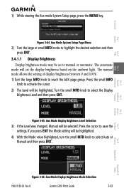
.... Turn the small MFD knob to reach the AUX page group. B Garmin G500 Pilot's Guide 3-43 Press the small MFD knob to save the settings. Figure 3-65 Aux Mode Display Brightness Level Selection 3) If the Level was changed, Manual will set to select Auto or Manual and then press ENT. Sec 5 Additional Sec 6 Annun. & Alerts Sec 7 Symbols Sec 8 Glossary Appendix A Appendix B Index Figure 3-66 Aux Mode Display Brightness Mode Selection...
.... Turn the small MFD knob to reach the AUX page group. B Garmin G500 Pilot's Guide 3-43 Press the small MFD knob to save the settings. Figure 3-65 Aux Mode Display Brightness Level Selection 3) If the Level was changed, Manual will set to select Auto or Manual and then press ENT. Sec 5 Additional Sec 6 Annun. & Alerts Sec 7 Symbols Sec 8 Glossary Appendix A Appendix B Index Figure 3-66 Aux Mode Display Brightness Mode Selection...

Pilots Guide
Page 119
... units. and then press ENT. B Garmin G500 Pilot's Guide 3-55 Sec 8 Glossary Appendix A Appendix B Index Sec 1 System Sec 2 PFD Sec 3 MFD Sec 4 Hazard Avoidance Features Sec 5 Additional Sec 6 Annun. & Alerts Sec 7 Symbols Figure 3-83 Active Flight Plan Page Menu Option Selection to Restore Defaults 3.5.1.3 Setting the Altitude Minimums Alerter 1) While viewing the Active Flight Plan Page of the FPL page group, press MENU to display the Active Flight Plan Page Options window. 2) Turn...
... units. and then press ENT. B Garmin G500 Pilot's Guide 3-55 Sec 8 Glossary Appendix A Appendix B Index Sec 1 System Sec 2 PFD Sec 3 MFD Sec 4 Hazard Avoidance Features Sec 5 Additional Sec 6 Annun. & Alerts Sec 7 Symbols Figure 3-83 Active Flight Plan Page Menu Option Selection to Restore Defaults 3.5.1.3 Setting the Altitude Minimums Alerter 1) While viewing the Active Flight Plan Page of the FPL page group, press MENU to display the Active Flight Plan Page Options window. 2) Turn...

Pilots Guide
Page 150
... 8 Index Appendix B 4-22 Garmin G500 Pilot's Guide 190-01102-02 Rev. NOTE: TIS and TAS are invisible to 3500 feet above the requesting aircraft. TIS receives traffic information from 3000 feet below to both Traffic Advisory Systems (TAS) and TIS. The type of other aircraft. Traffic is displayed according to TCAS symbology using three different symbols. 4.6.1 Traffic Map Page The Traffic Map Page is configured to show surrounding TIS traffic data in detection and...
... 8 Index Appendix B 4-22 Garmin G500 Pilot's Guide 190-01102-02 Rev. NOTE: TIS and TAS are invisible to 3500 feet above the requesting aircraft. TIS receives traffic information from 3000 feet below to both Traffic Advisory Systems (TAS) and TIS. The type of other aircraft. Traffic is displayed according to TCAS symbology using three different symbols. 4.6.1 Traffic Map Page The Traffic Map Page is configured to show surrounding TIS traffic data in detection and...

Pilots Guide
Page 226
... map page that can be displayed when selected. 1. The following is a list of pages where the SafeTaxi feature can be seen: • Navigation Map Page • NDB Information Page • Weather Datalink Page • VOR Information Page • Airport Information Page • User Waypoint Information Page • Intersection Information Page During ground operations the aircraft's position is displayed in view is selected for easy recognition of an active route...
... map page that can be displayed when selected. 1. The following is a list of pages where the SafeTaxi feature can be seen: • Navigation Map Page • NDB Information Page • Weather Datalink Page • VOR Information Page • Airport Information Page • User Waypoint Information Page • Intersection Information Page During ground operations the aircraft's position is displayed in view is selected for easy recognition of an active route...

Pilots Guide
Page 229
.... XM Satellite Radio uses one or two coded IDs, depending on the MFD Contact the installer if the Data Radio ID and the Audio Radio ID cannot be provided to XM Satellite Radio to play entertainment programming. B Garmin G500 Pilot's Guide 5-17 The optional XM® Radio entertainment feature of the Data Link Receiver • On the XM Information Page on the equipment. XM Satellite Radio services are included with the GDL 69A...
.... XM Satellite Radio uses one or two coded IDs, depending on the MFD Contact the installer if the Data Radio ID and the Audio Radio ID cannot be provided to XM Satellite Radio to play entertainment programming. B Garmin G500 Pilot's Guide 5-17 The optional XM® Radio entertainment feature of the Data Link Receiver • On the XM Information Page on the equipment. XM Satellite Radio services are included with the GDL 69A...
Pilots Guide
Page 230
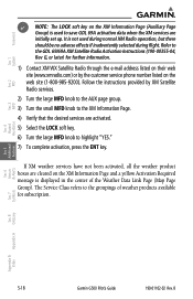
... Garmin G500 Pilot's Guide 190-01102-02 Rev. B Features Avoidance Hazard Sec 4 Additional Sec 5 & Alerts Annun. Follow the instructions provided by the customer service phone number listed on the XM Information Page and a yellow Activation Required message is not used to highlight "YES." 7) To complete activation, press the ENT key. Refer to the groupings of the Weather Data Link Page (Map Page Group). The Service Class refers to the GDL 69...
... Garmin G500 Pilot's Guide 190-01102-02 Rev. B Features Avoidance Hazard Sec 4 Additional Sec 5 & Alerts Annun. Follow the instructions provided by the customer service phone number listed on the XM Information Page and a yellow Activation Required message is not used to highlight "YES." 7) To complete activation, press the ENT key. Refer to the groupings of the Weather Data Link Page (Map Page Group). The Service Class refers to the GDL 69...

Pilots Guide
Page 235
... unmute the radio volume. 190-01102-02 Rev. Volume Bar Graph Volume Soft Key Labels Figure 5-18 XM Radio Volume Controls 3) Press MUTE to set the audio volume level, as well as mute the audio. B Garmin G500 Pilot's Guide 5-23 Appendix B Index Press the VOL + or VOL - While viewing the XM Radio page of the AUX page group, press the VOL soft key. 2. Foreword 6) Press ENT to save the selection...
... unmute the radio volume. 190-01102-02 Rev. Volume Bar Graph Volume Soft Key Labels Figure 5-18 XM Radio Volume Controls 3) Press MUTE to set the audio volume level, as well as mute the audio. B Garmin G500 Pilot's Guide 5-23 Appendix B Index Press the VOL + or VOL - While viewing the XM Radio page of the AUX page group, press the VOL soft key. 2. Foreword 6) Press ENT to save the selection...


