Pilots Guide
Page 7
... This product, its packaging, and its components contain chemicals known to the State of California to our web site at www.garmin.com/ prop65. If you have any questions or would like additional information, please refer to cause cancer, birth defects, or...Additional Sec 6 Annun. & Alerts Sec 7 Symbols Sec 8 Glossary Appendix A Appendix B Index 190-01102-02 Rev. This notice is installed. NOTE: Terrain-SVT is standard when the Garmin Synthetic Vision Technology™ (SVT) option is being provided in accordance with California's Proposition 65. B Garmin G500 Pilot's Guide v
... This product, its packaging, and its components contain chemicals known to the State of California to our web site at www.garmin.com/ prop65. If you have any questions or would like additional information, please refer to cause cancer, birth defects, or...Additional Sec 6 Annun. & Alerts Sec 7 Symbols Sec 8 Glossary Appendix A Appendix B Index 190-01102-02 Rev. This notice is installed. NOTE: Terrain-SVT is standard when the Garmin Synthetic Vision Technology™ (SVT) option is being provided in accordance with California's Proposition 65. B Garmin G500 Pilot's Guide v

Pilots Guide
Page 9
B Garmin G500 Pilot's Guide vii Sec 6 Annun. & Alerts Sec 7 Symbols Sec 8 ...330/330D (Optional 1-5 1.1.7 GTP 59 1-5 1.1.8 GDL 69/69A (Optional 1-6 1.1.9 GAD 43 (Optional 1-6 1.1.10 GWX 68 Weather Radar 1-7 1.1.11 Garmin Navigator Interface 1-7 1.1.12 Attitude Heading Reference System (AHRS 1-7 1.1.13 Secure Data Cards 1-8 1.1.14 Pilot Controls 1-9 1.1.14.1 PFD Knob 1-9 1.1.14.2 PFD... 1.3.3 System Settings 1-19 1.3.4 Display Backlighting 1-21 1.3.5 Dual GDU 620 Installations 1-22 1.3.5.1 Crossfill Information 1-22 1.3.5.2 Crossfill Selection 1-23 190-01102-02 Rev.
B Garmin G500 Pilot's Guide vii Sec 6 Annun. & Alerts Sec 7 Symbols Sec 8 ...330/330D (Optional 1-5 1.1.7 GTP 59 1-5 1.1.8 GDL 69/69A (Optional 1-6 1.1.9 GAD 43 (Optional 1-6 1.1.10 GWX 68 Weather Radar 1-7 1.1.11 Garmin Navigator Interface 1-7 1.1.12 Attitude Heading Reference System (AHRS 1-7 1.1.13 Secure Data Cards 1-8 1.1.14 Pilot Controls 1-9 1.1.14.1 PFD Knob 1-9 1.1.14.2 PFD... 1.3.3 System Settings 1-19 1.3.4 Display Backlighting 1-21 1.3.5 Dual GDU 620 Installations 1-22 1.3.5.1 Crossfill Information 1-22 1.3.5.2 Crossfill Selection 1-23 190-01102-02 Rev.
Pilots Guide
Page 11
Wind Vector 3-45 3.4.1.4 Synchronization (Dual Installations Only 3-46 3.4.1.5 Date and Time 3-47 3.4.1.6 MFD Display Units 3-48 3.4.1.7 System Display Units 3-49 3.4.2 XM Information (Optional 3-50 3.4.3 XM Entertainment Radio (Optional 3-51 3.4.4 System Status 3-... Feature Options (Optional 3-30 3.3.10.4 Aviation Feature Options 3-31 3.4 Aux Mode Pages 3-42 3.4.1 System Settings 3-42 3.4.1.1 Display Brightness 3-43 3.4.1.2 Airspeed Reference Marks 3-44 3.4.1.3 PFD Options - B Garmin G500 Pilot's Guide ix
Wind Vector 3-45 3.4.1.4 Synchronization (Dual Installations Only 3-46 3.4.1.5 Date and Time 3-47 3.4.1.6 MFD Display Units 3-48 3.4.1.7 System Display Units 3-49 3.4.2 XM Information (Optional 3-50 3.4.3 XM Entertainment Radio (Optional 3-51 3.4.4 System Status 3-... Feature Options (Optional 3-30 3.3.10.4 Aviation Feature Options 3-31 3.4 Aux Mode Pages 3-42 3.4.1 System Settings 3-42 3.4.1.1 Display Brightness 3-43 3.4.1.2 Airspeed Reference Marks 3-44 3.4.1.3 PFD Options - B Garmin G500 Pilot's Guide ix
Pilots Guide
Page 18
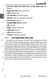
...GAD 43 Adapter (optional) • GWX 68 Weather Radar (optional) 1.1.1 Line Replaceable Units (LRU) This guide covers the operation of the G500 system. A failure or problem can be isolated to a particular LRU, which can be replaced quickly and easily. The system combines primary flight...be installed directly behind the instrument panel or in the G500 system. Each LRU has a particular function, or set of sub-units or Line Replaceable Units (LRUs). Sec 6 Symbols Sec 7 Appendix A Glossary Sec 8 Index Appendix B 1-2 Garmin G500 Pilot's Guide 190-01102-02 Rev. The G500 Avionics...
...GAD 43 Adapter (optional) • GWX 68 Weather Radar (optional) 1.1.1 Line Replaceable Units (LRU) This guide covers the operation of the G500 system. A failure or problem can be isolated to a particular LRU, which can be replaced quickly and easily. The system combines primary flight...be installed directly behind the instrument panel or in the G500 system. Each LRU has a particular function, or set of sub-units or Line Replaceable Units (LRUs). Sec 6 Symbols Sec 7 Appendix A Glossary Sec 8 Index Appendix B 1-2 Garmin G500 Pilot's Guide 190-01102-02 Rev. The G500 Avionics...

Pilots Guide
Page 22
...of spinning-mass gyros that provide attitude data to the autopilot and allow the gyro to be replaced by autopilot systems. The GAD 43 is installed remotely between the AHRS and an existing autopilot. A subscription to enable the GDL 69/69A capability. Foreword System Sec 1 PFD Sec 2... Hazard Sec 4 Additional Sec 5 & Alerts Annun. Sec 6 Symbols Sec 7 Appendix A Glossary Sec 8 Index Appendix B Figure 1-9 GAD 43 AHRS Adapter 1-6 Garmin G500 Pilot's Guide 190-01102-02 Rev. The analog signals from the GAD 43 mimic those of the audio signal. The GDL 69A is the same...
...of spinning-mass gyros that provide attitude data to the autopilot and allow the gyro to be replaced by autopilot systems. The GAD 43 is installed remotely between the AHRS and an existing autopilot. A subscription to enable the GDL 69/69A capability. Foreword System Sec 1 PFD Sec 2... Hazard Sec 4 Additional Sec 5 & Alerts Annun. Sec 6 Symbols Sec 7 Appendix A Glossary Sec 8 Index Appendix B Figure 1-9 GAD 43 AHRS Adapter 1-6 Garmin G500 Pilot's Guide 190-01102-02 Rev. The analog signals from the GAD 43 mimic those of the audio signal. The GDL 69A is the same...

Pilots Guide
Page 28
... if the system is not available for a second GPS or VOR/LOC receiver. Sec 5 & Alerts Annun. B NOTE: "AP TEST" is configured for all installations. PFD Pressing the PFD soft key displays the BRG1, BRG2, and BACK soft keys. CDI The CDI soft key toggles between the available receivers for...will only be present if the system is configured for a second GPS or VOR/LOC. Sec 6 Symbols Sec 7 Appendix A Glossary Sec 8 Index Appendix B 1-12 Garmin G500 Pilot's Guide 190-01102-02 Rev. In a dual GDU 620 system, the CDI keys in the GDU 620. GPS1 and GPS2 or VOR/LOC1 and...
... if the system is not available for a second GPS or VOR/LOC receiver. Sec 5 & Alerts Annun. B NOTE: "AP TEST" is configured for all installations. PFD Pressing the PFD soft key displays the BRG1, BRG2, and BACK soft keys. CDI The CDI soft key toggles between the available receivers for...will only be present if the system is configured for a second GPS or VOR/LOC. Sec 6 Symbols Sec 7 Appendix A Glossary Sec 8 Index Appendix B 1-12 Garmin G500 Pilot's Guide 190-01102-02 Rev. In a dual GDU 620 system, the CDI keys in the GDU 620. GPS1 and GPS2 or VOR/LOC1 and...
Pilots Guide
Page 29
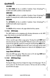
...14.5 MFD Bezel Keys Range (RNG) Pressing the Range arrow keys changes the range on the MFD pages. When the cursor is installed and enables airport sign posts. The keys also aid in the applicable window by turning the small and large MFD knobs. APTSIGNS The... 1 System Sec 2 PFD Sec 3 MFD Sec 4 Hazard Avoidance Features SYN TERR The SYN TERR soft key is available if Synthetic Vision Technology™ is installed. B Garmin G500 Pilot's Guide 1-13 Sec 5 Additional Sec 6 Annun. & Alerts Sec 7 Symbols Sec 8 Glossary Appendix A Appendix B Index 190-01102-02 Rev. HRZN...
...14.5 MFD Bezel Keys Range (RNG) Pressing the Range arrow keys changes the range on the MFD pages. When the cursor is installed and enables airport sign posts. The keys also aid in the applicable window by turning the small and large MFD knobs. APTSIGNS The... 1 System Sec 2 PFD Sec 3 MFD Sec 4 Hazard Avoidance Features SYN TERR The SYN TERR soft key is available if Synthetic Vision Technology™ is installed. B Garmin G500 Pilot's Guide 1-13 Sec 5 Additional Sec 6 Annun. & Alerts Sec 7 Symbols Sec 8 Glossary Appendix A Appendix B Index 190-01102-02 Rev. HRZN...
Pilots Guide
Page 32
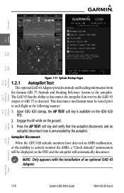
... Features Avoidance Hazard Sec 4 Additional Sec 5 & Alerts Annun. NOTE: Only appears with the installation of an optional GAD 43 Adapter. Symbols Sec 7 Appendix A Glossary Sec 8 Index Appendix B 1-16 Garmin G500 Pilot's Guide 190-01102-02 Rev. This disconnect mechanism must be displayed on the PFD and ...Sec 6 Figure 1-17 System Startup Pages 1.2.1 Autopilot Test The optional GAD 43 Adapter provides attitude and heading information from the Garmin GRS 77 Attitude and Heading Reference System to disconnect the autopilot if an error in the following manner: 1. Press the AP ...
... Features Avoidance Hazard Sec 4 Additional Sec 5 & Alerts Annun. NOTE: Only appears with the installation of an optional GAD 43 Adapter. Symbols Sec 7 Appendix A Glossary Sec 8 Index Appendix B 1-16 Garmin G500 Pilot's Guide 190-01102-02 Rev. This disconnect mechanism must be displayed on the PFD and ...Sec 6 Figure 1-17 System Startup Pages 1.2.1 Autopilot Test The optional GAD 43 Adapter provides attitude and heading information from the Garmin GRS 77 Attitude and Heading Reference System to disconnect the autopilot if an error in the following manner: 1. Press the AP ...
Pilots Guide
Page 35
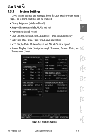
... (Mode and Level) • Airspeed References (Glide, Vr, Vx, and Vy) • PFD Options (Wind Vector) • Dual Unit Synchronization (CDI and Baro) - B Garmin G500 Pilot's Guide 1-19 Dual installations only • Date/Time (Date, Time, Time Format, and Time Offset) • MFD Display Units (Distance/Speed and Altitude/Vertical Speed) • System...
... (Mode and Level) • Airspeed References (Glide, Vr, Vx, and Vy) • PFD Options (Wind Vector) • Dual Unit Synchronization (CDI and Baro) - B Garmin G500 Pilot's Guide 1-19 Dual installations only • Date/Time (Date, Time, Time Format, and Time Offset) • MFD Display Units (Distance/Speed and Altitude/Vertical Speed) • System...
Pilots Guide
Page 38
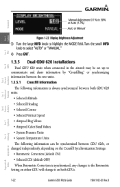
B Sec 6 Symbols Sec 7 Appendix A Glossary Sec 8 Index Appendix B 1-22 Garmin G500 Pilot's Guide 190-01102-02 Rev. Foreword Manual Adjustment 0.1% to 50% or Auto (1.7%) Auto or Manual System Sec 1 PFD Sec 2 MFD Sec 3 Features Avoidance... is always synchronized between both GDUs. & Alerts Annun. Turn the small MFD knob to select "AUTO" or "MANUAL." 4) Press ENT. 1.3.5 Dual GDU 620 Installations Dual GDU 620 units when connected in the aircraft may be synchronized between GDU 620s, or changed independently, depending on the Crossfill Synchronization Settings: •...
B Sec 6 Symbols Sec 7 Appendix A Glossary Sec 8 Index Appendix B 1-22 Garmin G500 Pilot's Guide 190-01102-02 Rev. Foreword Manual Adjustment 0.1% to 50% or Auto (1.7%) Auto or Manual System Sec 1 PFD Sec 2 MFD Sec 3 Features Avoidance... is always synchronized between both GDUs. & Alerts Annun. Turn the small MFD knob to select "AUTO" or "MANUAL." 4) Press ENT. 1.3.5 Dual GDU 620 Installations Dual GDU 620 units when connected in the aircraft may be synchronized between GDU 620s, or changed independently, depending on the Crossfill Synchronization Settings: •...
Pilots Guide
Page 45
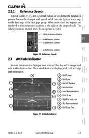
B Garmin G500 Pilot's Guide 2-5 Glide Reference Marker Vr Reference Marker Vx Reference Marker Vy Reference Marker Figure 2-8 Reference Speeds 2.3 Attitude Indicator Attitude information is cycled. The values you set are set during the installation process, but can be changed and turned on/off from the System Setup page on ), the Vspeeds are displayed at...
B Garmin G500 Pilot's Guide 2-5 Glide Reference Marker Vr Reference Marker Vx Reference Marker Vy Reference Marker Figure 2-8 Reference Speeds 2.3 Attitude Indicator Attitude information is cycled. The values you set are set during the installation process, but can be changed and turned on/off from the System Setup page on ), the Vspeeds are displayed at...

Pilots Guide
Page 46
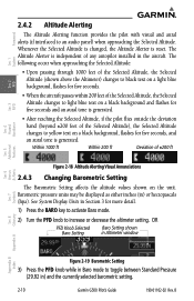
... 620 Attitude Indicator has been configured in your aircraft's standby Attitude Indicator. Sec 6 Symbols Sec 7 Appendix A Glossary Sec 8 Index Appendix B 2-6 Garmin G500 Pilot's Guide 190-01102-02 Rev. B Between 20º below ) is equal to 20º above the Roll Scale shifts with the roll pointer... are shown for intervening 5º increments, up to match the configuration of the zero. The Slip/Skid Indicator is configured during installation and can not be changed by the position of the pitch scale. Roll Pointer Roll Scale Zero Slip/Skid Indicator Figure 2-10 ...
... 620 Attitude Indicator has been configured in your aircraft's standby Attitude Indicator. Sec 6 Symbols Sec 7 Appendix A Glossary Sec 8 Index Appendix B 2-6 Garmin G500 Pilot's Guide 190-01102-02 Rev. B Between 20º below ) is equal to 20º above the Roll Scale shifts with the roll pointer... are shown for intervening 5º increments, up to match the configuration of the zero. The Slip/Skid Indicator is configured during installation and can not be changed by the position of the pitch scale. Roll Pointer Roll Scale Zero Slip/Skid Indicator Figure 2-10 ...
Pilots Guide
Page 50
... with visual and aural alerts (if interfaced to toggle between Standard Pressure (29.92 in) and the currently selected barometric setting. 2-10 Garmin G500 Pilot's Guide 190-01102-02 Rev. The following occur when approaching the Selected Altitude: • Upon passing through 1000 feet of the Selected...8226; After reaching the Selected Altitude, if the pilot flies outside the deviation band (beyond ±200 feet of any autopilot installed in the aircraft. See System Display Units in Section 3 for five seconds and an aural tone is generated. The Altitude Alerter is reset.
... with visual and aural alerts (if interfaced to toggle between Standard Pressure (29.92 in) and the currently selected barometric setting. 2-10 Garmin G500 Pilot's Guide 190-01102-02 Rev. The following occur when approaching the Selected Altitude: • Upon passing through 1000 feet of the Selected...8226; After reaching the Selected Altitude, if the pilot flies outside the deviation band (beyond ±200 feet of any autopilot installed in the aircraft. See System Display Units in Section 3 for five seconds and an aural tone is generated. The Altitude Alerter is reset.

Pilots Guide
Page 52
...the large and small MFD knobs to activate the selected value. Alerting is inhibited while the aircraft is ten feet. In dual installations, the minimums alerting altitude value may be synchronized on the ground and until the aircraft reaches 150 feet above the selected Minimum ...CLR key, it becomes a selectable value in 100 foot increments. Sec 6 Symbols Sec 7 Appendix A Glossary Sec 8 Index Appendix B 2-12 Garmin G500 Pilot's Guide 190-01102-02 Rev. Figure 2-21 Barometric Minimums Altitude Selection 3) Press ENT to change the Baro Minimums Altitude value. To set from...
...the large and small MFD knobs to activate the selected value. Alerting is inhibited while the aircraft is ten feet. In dual installations, the minimums alerting altitude value may be synchronized on the ground and until the aircraft reaches 150 feet above the selected Minimum ...CLR key, it becomes a selectable value in 100 foot increments. Sec 6 Symbols Sec 7 Appendix A Glossary Sec 8 Index Appendix B 2-12 Garmin G500 Pilot's Guide 190-01102-02 Rev. Figure 2-21 Barometric Minimums Altitude Selection 3) Press ENT to change the Baro Minimums Altitude value. To set from...
Pilots Guide
Page 53
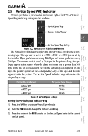
...Indicator Vertical speed data is presented on the tape, the pointer appears at ±2000, ±3000, or ±4000 fpm as set by installer) Airspeed Tape Range ±2000 fpm 60 kts ±3000 fpm 70 kts ±4000 fpm 80 kts Table 2-1 Vertical Speed Settings Setting ...installer. Major gradations are also available. A Vertical Speed bug and a bug setting are every 1000 fpm and minor gradations every 500 fpm. The tape can be scaled at the corresponding edge of the tape and the rate appears inside the pointer. The current vertical speed is greater than 100 fpm. B Garmin G500...
...Indicator Vertical speed data is presented on the tape, the pointer appears at ±2000, ±3000, or ±4000 fpm as set by installer) Airspeed Tape Range ±2000 fpm 60 kts ±3000 fpm 70 kts ±4000 fpm 80 kts Table 2-1 Vertical Speed Settings Setting ...installer. Major gradations are also available. A Vertical Speed bug and a bug setting are every 1000 fpm and minor gradations every 500 fpm. The tape can be scaled at the corresponding edge of the tape and the rate appears inside the pointer. The current vertical speed is greater than 100 fpm. B Garmin G500...
Pilots Guide
Page 75
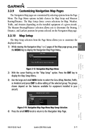
...Weather, Traffic, and Aviation depending on the Navigation Map page. 3.3.10 Map Setup The Map Setup selection from the Page Menu. B Garmin G500 Pilot's Guide 3-11 Appendix B Index The Measure Bearing/Distance selection allows you to customize the displayed items. 1) While viewing the Navigation...7 Symbols Sec 8 Glossary Appendix A Figure 3-13 Navigation Map Page Menu 2) With the cursor flashing on the features available for equipment installed in your aircraft. The groups shown depend on the "Map Setup" option. The Page Menu options include choices for Map Setup and ...
...Weather, Traffic, and Aviation depending on the Navigation Map page. 3.3.10 Map Setup The Map Setup selection from the Page Menu. B Garmin G500 Pilot's Guide 3-11 Appendix B Index The Measure Bearing/Distance selection allows you to customize the displayed items. 1) While viewing the Navigation...7 Symbols Sec 8 Glossary Appendix A Figure 3-13 Navigation Map Page Menu 2) With the cursor flashing on the features available for equipment installed in your aircraft. The groups shown depend on the "Map Setup" option. The Page Menu options include choices for Map Setup and ...

Pilots Guide
Page 94
...the Navigation Map. The Traffic soft key will be displayed at which data is limited to highlight the "Traffic" options. 3-30 Garmin G500 Pilot's Guide 190-01102-02 Rev. Traffic Selection Off All Traffic TA/PA TA Only Display Result No traffic displayed All types ...of the appropriate traffic device. The Traffic function requires the installation of traffic displayed Traffic Alerts and Proximity Alerts displayed Traffic Alerts Only displayed Table 3-3 Navigation Map Traffic Display Options Features Avoidance Hazard...
...the Navigation Map. The Traffic soft key will be displayed at which data is limited to highlight the "Traffic" options. 3-30 Garmin G500 Pilot's Guide 190-01102-02 Rev. Traffic Selection Off All Traffic TA/PA TA Only Display Result No traffic displayed All types ...of the appropriate traffic device. The Traffic function requires the installation of traffic displayed Traffic Alerts and Proximity Alerts displayed Traffic Alerts Only displayed Table 3-3 Navigation Map Traffic Display Options Features Avoidance Hazard...

Pilots Guide
Page 106
... only the Airspeed Reference default settings. 3-42 Garmin G500 Pilot's Guide 190-01102-02 Rev. Foreword System Sec 1 3.4 Aux Mode Pages The Aux mode provides pages for System Setup, XM Information (if installed), and system Status. 3.4.1 System Settings G500 system settings are restored by the installer during installation are managed from the Aux Mode System Setup...
... only the Airspeed Reference default settings. 3-42 Garmin G500 Pilot's Guide 190-01102-02 Rev. Foreword System Sec 1 3.4 Aux Mode Pages The Aux mode provides pages for System Setup, XM Information (if installed), and system Status. 3.4.1 System Settings G500 system settings are restored by the installer during installation are managed from the Aux Mode System Setup...

Pilots Guide
Page 108
... tape at the selected speed when the value is cycled, the values you set will be retained. The next value will now be highlighted. 3-44 Garmin G500 Pilot's Guide 190-01102-02 Rev. Default reference airspeeds are adjusted with this function. System Sec 1 PFD Sec 2 MFD Sec 3 Features Avoidance Hazard Sec 4 Additional.../Off setting will be highlighted. Foreword 3.4.1.2 Airspeed Reference Marks The Best Glide, Vr, Vx, and Vy airspeed reference marks for the PFD are set during installation. B Index Appendix B
... tape at the selected speed when the value is cycled, the values you set will be retained. The next value will now be highlighted. 3-44 Garmin G500 Pilot's Guide 190-01102-02 Rev. Default reference airspeeds are adjusted with this function. System Sec 1 PFD Sec 2 MFD Sec 3 Features Avoidance Hazard Sec 4 Additional.../Off setting will be highlighted. Foreword 3.4.1.2 Airspeed Reference Marks The Best Glide, Vr, Vx, and Vy airspeed reference marks for the PFD are set during installation. B Index Appendix B

Pilots Guide
Page 110
... large MFD knob to select "ON" or "OFF." 3) Press ENT. Sec 6 Symbols Sec 7 Appendix A Glossary Sec 8 Index Appendix B 3-46 Garmin G500 Pilot's Guide 190-01102-02 Rev. Figure 3-69 Dual Unit Synchronization 2) Turn the small MFD knob to highlight "CDI" or "BARO" in the "...and share information by "Crossfilling" or synchronizing information between the two units. B Foreword System Sec 1 PFD Sec 2 3.4.1.4 Synchronization (Dual Installations Only) Dual GDU 620 units when connected in the aircraft may be set up to the Barometric Setting on either GDU will change it...
... large MFD knob to select "ON" or "OFF." 3) Press ENT. Sec 6 Symbols Sec 7 Appendix A Glossary Sec 8 Index Appendix B 3-46 Garmin G500 Pilot's Guide 190-01102-02 Rev. Figure 3-69 Dual Unit Synchronization 2) Turn the small MFD knob to highlight "CDI" or "BARO" in the "...and share information by "Crossfilling" or synchronizing information between the two units. B Foreword System Sec 1 PFD Sec 2 3.4.1.4 Synchronization (Dual Installations Only) Dual GDU 620 units when connected in the aircraft may be set up to the Barometric Setting on either GDU will change it...


