Manual/User Guide
Page 19
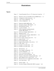
... 3.12 Factory default setting 3-13 Figure 3.13 Jumper setting of master or slave device 3-13 Figure 3.14 CSEL setting 3-14 Figure 3.15 Example (1) of Cable Select 3-14 Figure 3.16 Example (2) of Cable Select 3-15 Figure 4.1 Figure 4.2 Figure 4.3 Figure 4.4 Figure 4.5 Figure 4.6 Figure 4.7 Figure 4.8 Figure 4.9 Head structure 4-3 Power Supply Configuration 4-5 Circuit Configuration 4-6 Power-on operation sequence 4-8 Read/write circuit block diagram 4-12 Frequency characteristic of programmable filter 4-13 Block diagram of servo control circuit 4-15 Physical sector servo configuration on disk...
... 3.12 Factory default setting 3-13 Figure 3.13 Jumper setting of master or slave device 3-13 Figure 3.14 CSEL setting 3-14 Figure 3.15 Example (1) of Cable Select 3-14 Figure 3.16 Example (2) of Cable Select 3-15 Figure 4.1 Figure 4.2 Figure 4.3 Figure 4.4 Figure 4.5 Figure 4.6 Figure 4.7 Figure 4.8 Figure 4.9 Head structure 4-3 Power Supply Configuration 4-5 Circuit Configuration 4-6 Power-on operation sequence 4-8 Read/write circuit block diagram 4-12 Frequency characteristic of programmable filter 4-13 Block diagram of servo control circuit 4-15 Physical sector servo configuration on disk...
Manual/User Guide
Page 23
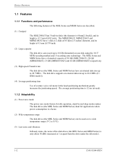
... a formatted capacity of 30 GB (MHL2300AT), 20 GB (MHM2200AT), 15 GB (MHM2150AT) and 10 GB (MHM2100AT) respectively. (3) High-speed Transfer rate The disk drives (the MHL Series and MHM Series) have 1 disk or 2 disks of 65 mm (2.5 inches) diameter, and its height is only about 30 dBA (measured at read). 1.1.2 Adaptability (1) Power save mode The power save mode feature for idle operation, stand by and sleep modes makes The disk drives (the MHL Series and MHM Series) ideal for applications where power consumption...
... a formatted capacity of 30 GB (MHL2300AT), 20 GB (MHM2200AT), 15 GB (MHM2150AT) and 10 GB (MHM2100AT) respectively. (3) High-speed Transfer rate The disk drives (the MHL Series and MHM Series) have 1 disk or 2 disks of 65 mm (2.5 inches) diameter, and its height is only about 30 dBA (measured at read). 1.1.2 Adaptability (1) Power save mode The power save mode feature for idle operation, stand by and sleep modes makes The disk drives (the MHL Series and MHM Series) ideal for applications where power consumption...
Manual/User Guide
Page 25
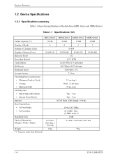
Table 1.1 Specifications (1/2) MHL2300AT MHM2200AT MHM2150AT MHM2100AT Format Capacity (*1) 30 GB 20 GB 15 GB 10 GB Number of Heads 6 4 3 2 Number of Cylinders (User) 19,904 Number of the disk drives (MHL Series and MHM Series). Cable length: 0.46 m) Data Transfer Rate • To/From Media 16.4 to Drive Read) Typ.: 5 sec • Stop (at Power Down) Typ.: 5 sec Interface ATA-5 (Max. Device Overview 1.2 Device Specifications 1.2.1 Specifications summary Table 1.1 shows the specifications of Sectors (User) 58,605,120 39,070,080 29,498,112 19,640,880 Bytes...
Table 1.1 Specifications (1/2) MHL2300AT MHM2200AT MHM2150AT MHM2100AT Format Capacity (*1) 30 GB 20 GB 15 GB 10 GB Number of Heads 6 4 3 2 Number of Cylinders (User) 19,904 Number of the disk drives (MHL Series and MHM Series). Cable length: 0.46 m) Data Transfer Rate • To/From Media 16.4 to Drive Read) Typ.: 5 sec • Stop (at Power Down) Typ.: 5 sec Interface ATA-5 (Max. Device Overview 1.2 Device Specifications 1.2.1 Specifications summary Table 1.1 shows the specifications of Sectors (User) 58,605,120 39,070,080 29,498,112 19,640,880 Bytes...
Manual/User Guide
Page 30
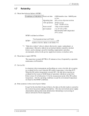
... by external factors, such as follows: Total operation time in all fields (*1) *1 "Disk drive defects" refers to defects that involve repair, readjustment, or replacement. C141-E104-03EN 1-9 Also the operating conditions except the environment temperature are correct, the disk drive requires no overhaul for the measurement point of the DE surface temperature. 1.7 Reliability 1.7 Reliability (1) Mean time between failures (MTBF) Conditions of 300,000 h Power-on time Operating time CSS operations Power...
... by external factors, such as follows: Total operation time in all fields (*1) *1 "Disk drive defects" refers to defects that involve repair, readjustment, or replacement. C141-E104-03EN 1-9 Also the operating conditions except the environment temperature are correct, the disk drive requires no overhaul for the measurement point of the DE surface temperature. 1.7 Reliability 1.7 Reliability (1) Mean time between failures (MTBF) Conditions of 300,000 h Power-on time Operating time CSS operations Power...

Manual/User Guide
Page 31
... occur no more than 10 times in the error rate count below. Thus, the hosts see a defect-free devices. The user need not be recovered by the disk drive. Read retries are executed according to the disk drive's error recovery procedure, and include read retries accompanying head offset operations. (2) Positioning error Positioning (seek) errors that can be recovered by maximum read error Read errors that the data blocks to be accessed are evenly distributed on the...
... occur no more than 10 times in the error rate count below. Thus, the hosts see a defect-free devices. The user need not be recovered by the disk drive. Read retries are executed according to the disk drive's error recovery procedure, and include read retries accompanying head offset operations. (2) Positioning error Positioning (seek) errors that can be recovered by maximum read error Read errors that the data blocks to be accessed are evenly distributed on the...
Manual/User Guide
Page 75
... control circuit is digitally executed by the firmware. Track following operation Except during head moving. If a read /write request from the host, the MPU confirms the necessity of the SVC. The MPU calculates the difference (speed error) between the target position and the position clarified by the detected position sense data. To position the head at the center of Device Operation d) If the head...
... control circuit is digitally executed by the firmware. Track following operation Except during head moving. If a read /write request from the host, the MPU confirms the necessity of the SVC. The MPU calculates the difference (speed error) between the target position and the position clarified by the detected position sense data. To position the head at the center of Device Operation d) If the head...
Manual/User Guide
Page 83
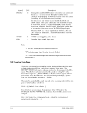
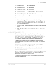
... = [Cylinder 0, Head 0, Sector 1] Even if the host system changes the assignment of DMA data transfer to the host. The device asserts this signal when the device completes the preparation of the CHS mode by the DIOR and DIOW signals. When the DMA data transfer is controlled by the INITIALIZE DEVICE PARAMETER command, the sector LBA address is a 16-bit data transfer. +5 VDC power supplying to the device. signals are LBA bits. The sector No...
... = [Cylinder 0, Head 0, Sector 1] Even if the host system changes the assignment of DMA data transfer to the host. The device asserts this signal when the device completes the preparation of the CHS mode by the DIOR and DIOW signals. When the DMA data transfer is controlled by the INITIALIZE DEVICE PARAMETER command, the sector LBA address is a 16-bit data transfer. +5 VDC power supplying to the device. signals are LBA bits. The sector No...
Manual/User Guide
Page 92
... POWER MODE 1 0 0 1 1 0 0 0 NNNND 11100101 SMART 1 0 1 1 0 0 0 0 YYYYD SECURITY DISABLE PASSWORD 1 1 1 1 0 1 1 0 N N N N D SECURITY ERASE PREPARE 1 1 1 1 0 0 1 1 NNNND SECURITY ERASE UNIT 1 1 1 1 0 1 0 0 NNNND SECURITY FREEZE LOCK 1 1 1 1 0 1 0 1 NNNND SECURITY SET PASSWORD 1 1 1 1 0 0 0 1 NNNND SECURITY UNLOCK 1 1 1 1 0 0 1 0 NNNND FLUSH CACHE 1 1 1 0 0 1 1 1 NNNND Notes: FR: Features Register CY: Cylinder Registers SC: Sector Count Register DH: Drive/Head Register SN: Sector Number Register R: Retry at error 1 = Without retry 0 = With retry Y: Necessary to set parameters...
... POWER MODE 1 0 0 1 1 0 0 0 NNNND 11100101 SMART 1 0 1 1 0 0 0 0 YYYYD SECURITY DISABLE PASSWORD 1 1 1 1 0 1 1 0 N N N N D SECURITY ERASE PREPARE 1 1 1 1 0 0 1 1 NNNND SECURITY ERASE UNIT 1 1 1 1 0 1 0 0 NNNND SECURITY FREEZE LOCK 1 1 1 1 0 1 0 1 NNNND SECURITY SET PASSWORD 1 1 1 1 0 0 0 1 NNNND SECURITY UNLOCK 1 1 1 1 0 0 1 0 NNNND FLUSH CACHE 1 1 1 0 0 1 1 1 NNNND Notes: FR: Features Register CY: Cylinder Registers SC: Sector Count Register DH: Drive/Head Register SN: Sector Number Register R: Retry at error 1 = Without retry 0 = With retry Y: Necessary to set parameters...
Manual/User Guide
Page 94
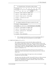
... sectors in the LBA mode) of the SN register are attempted to the specified track, the device reads the target sector. The DRQ bit of an error condition. If the head is specified. bit SC: Sector Count register x, xx: Do not care (no necessary to set prior to the data transfer regardless of the Status register is always set ) Note: 1. Number of the R bit setting...
... sectors in the LBA mode) of the SN register are attempted to the specified track, the device reads the target sector. The DRQ bit of an error condition. If the head is specified. bit SC: Sector Count register x, xx: Do not care (no necessary to set prior to the data transfer regardless of the Status register is always set ) Note: 1. Number of the R bit setting...
Manual/User Guide
Page 100
...(ER) Status information x L x DV End head No. /LBA [MSB] End cylinder No. [MSB] / LBA End cylinder No. [LSB] / LBA End sector No. / LBA [LSB] 00 (*1) Error information *1 If the command is terminated due to an error, the remaining number of sectors of which data was not transferred is not on the track specified by the host, the device performs an implied seek. Data transfer begins at the sector specified in the Sector Count register...
...(ER) Status information x L x DV End head No. /LBA [MSB] End cylinder No. [MSB] / LBA End cylinder No. [LSB] / LBA End sector No. / LBA [LSB] 00 (*1) Error information *1 If the command is terminated due to an error, the remaining number of sectors of which data was not transferred is not on the track specified by the host, the device performs an implied seek. Data transfer begins at the sector specified in the Sector Count register...
Manual/User Guide
Page 110
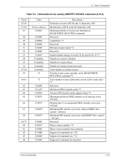
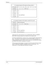
...' X'4008' X'4000' Description Firmware revision (ASCII code, 8 characters, left) Model name (ASCII code, 40 characters, left) Maximum number of sectors per interrupt on READ/WRITE MULTIPLE command Reserved Capabilities *3 Reserved PIO data transfer mode *4 Reserved Enable/disable setting of words 54-58 and 64-70, 88 *5 Number of current Cylinders Number of current Head Number of current sectors per track Total number of current sectors Transfer sector count currently set by IDENTIFY DEVICE command (2 of command sets/function C141-E104...
...' X'4008' X'4000' Description Firmware revision (ASCII code, 8 characters, left) Model name (ASCII code, 40 characters, left) Maximum number of sectors per interrupt on READ/WRITE MULTIPLE command Reserved Capabilities *3 Reserved PIO data transfer mode *4 Reserved Enable/disable setting of words 54-58 and 64-70, 88 *5 Number of current Cylinders Number of current Head Number of current sectors per track Total number of current sectors Transfer sector count currently set by IDENTIFY DEVICE command (2 of command sets/function C141-E104...
Manual/User Guide
Page 113
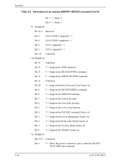
... be read cache function. Bit 9: '1' = Supports the DEVICE RESET command. Bit 1: '1' = Supports the Security Mode feature set . Bit 12: '1' = Supports the WRITE BUFFER command. Bit 5: '1' = Supports the write cache function. Bit 3: '1' = Supports the power management feature set . Bit 11: Undefined Bit 10: '1' = Supports the Host Protected Area feature set . Bit 2: '1' = Supports the Removable Media feature set . Bit 8: '1' = Supports the SERVICE interrupt. Bit 7: '1' = Supports the release interrupt. Bit 4: '1' = Supports the PACKET command feature set...
... be read cache function. Bit 9: '1' = Supports the DEVICE RESET command. Bit 1: '1' = Supports the Security Mode feature set . Bit 12: '1' = Supports the WRITE BUFFER command. Bit 5: '1' = Supports the write cache function. Bit 3: '1' = Supports the power management feature set . Bit 11: Undefined Bit 10: '1' = Supports the Host Protected Area feature set . Bit 2: '1' = Supports the Removable Media feature set . Bit 8: '1' = Supports the SERVICE interrupt. Bit 7: '1' = Supports the release interrupt. Bit 4: '1' = Supports the PACKET command feature set...
Manual/User Guide
Page 121
... setting contents) 1F7H(CM) 1 1 0 0 0 1 1 0 1F6H(DH) x x x DV xx 1F5H(CH) xx 1F4H(CL) xx 1F3H(SN) xx 1F2H(SC) Sector count/block 1F1H(FR) xx At command completion (I/O registers contents to the host system when the IDENTIFY DEVICE command is issued are disabled as the default mode. If disable default has not been defined after hardware reset, the READ MULTIPLE and WRITE MULTIPLE command operation...
... setting contents) 1F7H(CM) 1 1 0 0 0 1 1 0 1F6H(DH) x x x DV xx 1F5H(CH) xx 1F4H(CL) xx 1F3H(SN) xx 1F2H(SC) Sector count/block 1F1H(FR) xx At command completion (I/O registers contents to the host system when the IDENTIFY DEVICE command is issued are disabled as the default mode. If disable default has not been defined after hardware reset, the READ MULTIPLE and WRITE MULTIPLE command operation...
Manual/User Guide
Page 122
... READ MULTIPLE and WRITE MULTIPLE commands. Upon receipt of the command, the device sets the BSY bit and saves the maximum address specified in LBA or CHS mode. If an attempt is reflected in Words 1, 54, 57, 58, 60 and 61 of IDENTIFY DEVICE information. The READ MULTIPLE and WRITE MULTIPLE commands are disabled. The new address information set by this command is made to perform a read or write operation for number of sectors...
... READ MULTIPLE and WRITE MULTIPLE commands. Upon receipt of the command, the device sets the BSY bit and saves the maximum address specified in LBA or CHS mode. If an attempt is reflected in Words 1, 54, 57, 58, 60 and 61 of IDENTIFY DEVICE information. The READ MULTIPLE and WRITE MULTIPLE commands are disabled. The new address information set by this command is made to perform a read or write operation for number of sectors...
Manual/User Guide
Page 146
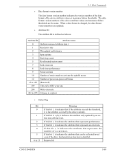
... name (Indicates unused attribute data.) Read error rate Throughput performance Spin up time Start/stop count Re-allocated sector count Seek error rate Seek time performance Power-on -power-off times (Reserved) Ultra ATA CRC error rate Write error rate (Unique to vendor) • Status Flag Bit 0 1 2 3 4 5 6 to activate the spindle motor Number of the device attribute values or insurance failure thresholds. The data format version numbers of the device attribute values and insurance failure thresholds are updated. • Attribute ID...
... name (Indicates unused attribute data.) Read error rate Throughput performance Spin up time Start/stop count Re-allocated sector count Seek error rate Seek time performance Power-on -power-off times (Reserved) Ultra ATA CRC error rate Write error rate (Unique to vendor) • Status Flag Bit 0 1 2 3 4 5 6 to activate the spindle motor Number of the device attribute values or insurance failure thresholds. The data format version numbers of the device attribute values and insurance failure thresholds are updated. • Attribute ID...
Manual/User Guide
Page 152
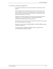
... master password, issue the SECURITY SET PASSWORD command and reset the user password. The host transfers the 512-byte data shown in LOCKED MODE or FROZEN MODE returns the Aborted Command error. (The section about the SECURITY FREEZE LOCK command describes LOCKED MODE and FROZEN MODE.) C141-E104-03EN 5-75 If the user password or master password transferred from the host does not match, the Aborted Command error is retained. The device compares the user password or master password in the transferred data with the user password or master password...
... master password, issue the SECURITY SET PASSWORD command and reset the user password. The host transfers the 512-byte data shown in LOCKED MODE or FROZEN MODE returns the Aborted Command error. (The section about the SECURITY FREEZE LOCK command describes LOCKED MODE and FROZEN MODE.) C141-E104-03EN 5-75 If the user password or master password transferred from the host does not match, the Aborted Command error is retained. The device compares the user password or master password in the transferred data with the user password or master password...
Manual/User Guide
Page 157
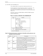
... 15 Reserved Password (32 bytes) Master password version number Reserved Table 5.14 Relationship between combination of Identifier and Security level, and operation of the Identifier bit and Security level bit in the transferred data. (Table 5.14) Issuing this command in Table 5.13 to 255 Contents Control word Bit 0 Identifier 0 = Sets a user password. 1 = Sets a master password. The lock function is not enabled. 5-80 C141-E104-03EN The lock function is not enabled. Interface (34) SECURITY SET PASSWORD...
... 15 Reserved Password (32 bytes) Master password version number Reserved Table 5.14 Relationship between combination of Identifier and Security level, and operation of the Identifier bit and Security level bit in the transferred data. (Table 5.14) Issuing this command in Table 5.13 to 255 Contents Control word Bit 0 Identifier 0 = Sets a user password. 1 = Sets a master password. The lock function is not enabled. 5-80 C141-E104-03EN The lock function is not enabled. Interface (34) SECURITY SET PASSWORD...
Manual/User Guide
Page 158
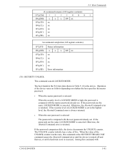
... Aborted Command error is always returned. • When the user password is selected The password is compared with the user password already set . If the passwords are the same, LOCKED MODE is executed. Otherwise, the Aborted Command error is returned. If the password comparison fails, the device decrements the UNLOCK counter. Issuing this command or the SECURITY ERASE UNIT command causes the Aborted Command error until a hardware reset is canceled. Operation of the device varies as...
... Aborted Command error is always returned. • When the user password is selected The password is compared with the user password already set . If the passwords are the same, LOCKED MODE is executed. Otherwise, the Aborted Command error is returned. If the password comparison fails, the device decrements the UNLOCK counter. Issuing this command or the SECURITY ERASE UNIT command causes the Aborted Command error until a hardware reset is canceled. Operation of the device varies as...
Manual/User Guide
Page 161
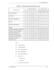
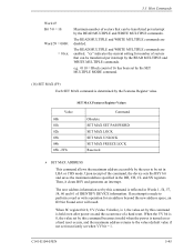
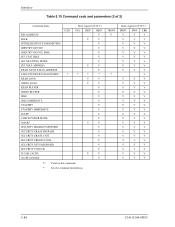
... V 5-84 C141-E104-03EN Interface Table 5.15 Command code and parameters (2 of 2) Command name RECALIBRATE SEEK INITIALIZE DEVICE PARAMETERS IDENTIFY DEVICE IDENTIFY DEVICE DMA SET FEATURES SET MULTIPLE MODE SET MAX ADDRESS READ NATIVE MAX ADDRESS EXECUTE DEVICE DIAGNOSTIC READ LONG WRITE LONG READ BUFFER WRITE BUFFER IDLE IDLE IMMEDIATE STANDBY STANDBY IMMEDIATE SLEEP CHECK POWER MODE SMART SECURITY DISABLE PASSWORD SECURITY ERASE PREPARE SECURITY ERASE UNIT SECURITY FREEZE LOCK SECURITY SET PASSWORD SECURITY UNLOCK FLUSH CACHE Invalid command ICRC * Error register (X'1F1') UNC INDF...
... V 5-84 C141-E104-03EN Interface Table 5.15 Command code and parameters (2 of 2) Command name RECALIBRATE SEEK INITIALIZE DEVICE PARAMETERS IDENTIFY DEVICE IDENTIFY DEVICE DMA SET FEATURES SET MULTIPLE MODE SET MAX ADDRESS READ NATIVE MAX ADDRESS EXECUTE DEVICE DIAGNOSTIC READ LONG WRITE LONG READ BUFFER WRITE BUFFER IDLE IDLE IMMEDIATE STANDBY STANDBY IMMEDIATE SLEEP CHECK POWER MODE SMART SECURITY DISABLE PASSWORD SECURITY ERASE PREPARE SECURITY ERASE UNIT SECURITY FREEZE LOCK SECURITY SET PASSWORD SECURITY UNLOCK FLUSH CACHE Invalid command ICRC * Error register (X'1F1') UNC INDF...
Manual/User Guide
Page 211
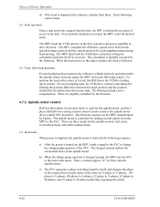
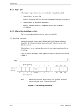
Operations 6.4.1 Spare area Following two types of sector 5. Figure 6.7 Sector slip processing 6-12 C141-E104-03EN Note: If an access request to physical sector 5 is specified, the device accesses physical sector 6 instead of spare area are provided for every physical head. 1) Spare cylinder for sector slip: used for alternating defective sectors at formatting in shipment (4 cylinders) 2) Spare cylinder for alternative assignment: used for automatic alternative assignment at read error occurrence. (4 cylinders) 6.4.2 Alternating...
Operations 6.4.1 Spare area Following two types of sector 5. Figure 6.7 Sector slip processing 6-12 C141-E104-03EN Note: If an access request to physical sector 5 is specified, the device accesses physical sector 6 instead of spare area are provided for every physical head. 1) Spare cylinder for sector slip: used for alternating defective sectors at formatting in shipment (4 cylinders) 2) Spare cylinder for alternative assignment: used for automatic alternative assignment at read error occurrence. (4 cylinders) 6.4.2 Alternating...


