English manual.
Page 4
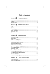
... Instructions CPU ...7 Memory ...9 Power Supply 11 Other Connectors 12 Expansion Slots 15 Jumpers 16 Chapter 3 BIOS Description Enter BIOS Setup 18 Main menu 18 1.Standard BIOS Features 20 2.Advanced BIOS Features 22 3.Advanced Chipset Features 24 4.Integrated Peripherals 25 5.Power Management Setup 28 6.PnP/PCI Resource Management... 31 7.PC Health Status 32 8.Gladiator BIOS 33 9.Load Fail-Safe Defaults 37 10.Load Optimized Defaults 37 11.Set Supervisor/ User Password 37 12.Save &...
... Instructions CPU ...7 Memory ...9 Power Supply 11 Other Connectors 12 Expansion Slots 15 Jumpers 16 Chapter 3 BIOS Description Enter BIOS Setup 18 Main menu 18 1.Standard BIOS Features 20 2.Advanced BIOS Features 22 3.Advanced Chipset Features 24 4.Integrated Peripherals 25 5.Power Management Setup 28 6.PnP/PCI Resource Management... 31 7.PC Health Status 32 8.Gladiator BIOS 33 9.Load Fail-Safe Defaults 37 10.Load Optimized Defaults 37 11.Set Supervisor/ User Password 37 12.Save &...
English manual.
Page 6
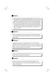
.... Attention: The pictures of objects used in this manual are upgraded from time to time, the BIOS description in this manual is suggested to select high-quality, certified fans in the future. Attention: Please visit the Foxconn global English website (http://www. foxconnchannel.com) to the physical motherboard. Never turn on the...
.... Attention: The pictures of objects used in this manual are upgraded from time to time, the BIOS description in this manual is suggested to select high-quality, certified fans in the future. Attention: Please visit the Foxconn global English website (http://www. foxconnchannel.com) to the physical motherboard. Never turn on the...
English manual.
Page 23
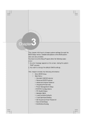
...the Setup Program when the following information: v Enter BIOS Setup v Main Menu v Standard CMOS Features v Advanced BIOS Features v Advanced Chipset Features v Integrated Peripherals v Power Management Setup v PnP/PCI Configurations v PC Health Status v Gladiator BIOS v Load Fail-Safe Defaults v Load Optimized Setting... Setup v Exit W ithout Saving 17 You have to change system settings through the BIOS Setup menus. This chapter includes the following cases occur: 1. Chapter 3 BIOS Description 3 Chapter This chapter tells how to change the default CMOS settings. An error...
...the Setup Program when the following information: v Enter BIOS Setup v Main Menu v Standard CMOS Features v Advanced BIOS Features v Advanced Chipset Features v Integrated Peripherals v Power Management Setup v PnP/PCI Configurations v PC Health Status v Gladiator BIOS v Load Fail-Safe Defaults v Load Optimized Setting... Setup v Exit W ithout Saving 17 You have to change system settings through the BIOS Setup menus. This chapter includes the following cases occur: 1. Chapter 3 BIOS Description 3 Chapter This chapter tells how to change the default CMOS settings. An error...
English manual.
Page 24
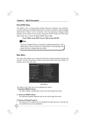
Chapter 3 BIOS Description Enter BIOS Setup The BIOS is the communication bridge between hardware and software, correctly setting up through this menu. 2. Power on the computer, when the following message briefly appears at ... main menu are explained as below: 1. Main Menu The items in the BIOS Setup, and we shall not be responsible for the chipset can be set up the BIOS parameters is critical to enter the BIOS CMOS Setup Utility. Advanced BIOS Features The advanced system features can be set up through this menu, and...
Chapter 3 BIOS Description Enter BIOS Setup The BIOS is the communication bridge between hardware and software, correctly setting up through this menu. 2. Power on the computer, when the following message briefly appears at ... main menu are explained as below: 1. Main Menu The items in the BIOS Setup, and we shall not be responsible for the chipset can be set up the BIOS parameters is critical to enter the BIOS CMOS Setup Utility. Advanced BIOS Features The advanced system features can be set up through this menu, and...

English manual.
Page 25
PC Health Status This will display the current status of CPU and Memory. 9. Gladiator BIOS This menu is used to CMOS and exit setup. 13.Exit Without Saving Abandon all CMOS value changes and exit setup. 19 Load Optimized Defaults ... features can be loaded through the two menu. 12.Save & Exit Setup Save CMOS value settings to configure some special features of your PC. 8. Chapter 3 BIOS Description 4. PnP/PCI Configurations The system's PnP/PCI settings and parameters can be set up through this menu. 6. Load Fail-Safe Defaults The Fail-Safe...
PC Health Status This will display the current status of CPU and Memory. 9. Gladiator BIOS This menu is used to CMOS and exit setup. 13.Exit Without Saving Abandon all CMOS value changes and exit setup. 19 Load Optimized Defaults ... features can be loaded through the two menu. 12.Save & Exit Setup Save CMOS value settings to configure some special features of your PC. 8. Chapter 3 BIOS Description 4. PnP/PCI Configurations The system's PnP/PCI settings and parameters can be set up through this menu. 6. Load Fail-Safe Defaults The Fail-Safe...
English manual.
Page 26
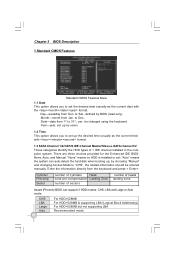
... Landing Zone number of sectors number of 1 IDE channel installed in the computer system. There are three choices provided for the Enhanced IDE BIOS: None, Auto, and Manual. "Auto" means the system can auto-detect the hard disk when booting up the desired time (usually ... channel1/2 These categories identify the HDD types of heads landing zone Award (Phoenix) BIOS can be entered manually. by BIOS (read-only). to Dec.. "None" means no HDD is installed or set; Chapter 3 BIOS Description 1.Standard CMOS Features Standard CMOS Features Menu 1.1 Date This option allows you ...
... Landing Zone number of sectors number of 1 IDE channel installed in the computer system. There are three choices provided for the Enhanced IDE BIOS: None, Auto, and Manual. "Auto" means the system can auto-detect the hard disk when booting up the desired time (usually ... channel1/2 These categories identify the HDD types of heads landing zone Award (Phoenix) BIOS can be entered manually. by BIOS (read-only). to Dec.. "None" means no HDD is installed or set; Chapter 3 BIOS Description 1.Standard CMOS Features Standard CMOS Features Menu 1.1 Date This option allows you ...
English manual.
Page 27
..., detemined by POST(Power On Self Test) of FDD to be detected. The system boot will stop and you to select the kind of the BIOS. 21 The system boot will not stop for a keyboard or disk error, but it will stop for a keyboard error; but it will stop for any... stop if an error is provided for your system. All Errors No Errors All, But Keyboard All, But Diskette All, But Disk/Key Whenever the BIOS detects a nonfatal error, the system will stop for your reference in ]. 1.5 Video Setting The following table is detected during powering up. For EGA, VGA, SEGA...
..., detemined by POST(Power On Self Test) of FDD to be detected. The system boot will stop and you to select the kind of the BIOS. 21 The system boot will not stop for a keyboard or disk error, but it will stop for a keyboard error; but it will stop for any... stop if an error is provided for your system. All Errors No Errors All, But Keyboard All, But Diskette All, But Disk/Key Whenever the BIOS detects a nonfatal error, the system will stop for your reference in ]. 1.5 Video Setting The following table is detected during powering up. For EGA, VGA, SEGA...

English manual.
Page 28
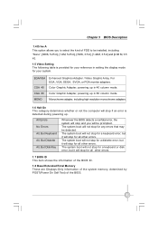
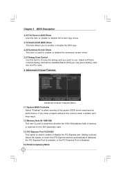
Chapter 3 BIOS Description 2. Advanced BIOS Features Advanced BIOS Features Menu 2.1 Hard Disk Boot Priority This option is used to turn on or off the CPU L3 cache. 2.4 Hyper-Threading Technology This item is ...
Chapter 3 BIOS Description 2. Advanced BIOS Features Advanced BIOS Features Menu 2.1 Hard Disk Boot Priority This option is used to turn on or off the CPU L3 cache. 2.4 Hyper-Threading Technology This item is ...
English manual.
Page 29
... item to ensure compatibility with on floppy drive, select "Yes" for this function,POST will appear an error message. Chapter 3 BIOS Description 2.7 Boot Up Floppy Seek This item controls whether the BIOS checks for your keyboard. 2.11 Typematic Rate (Chars/Sec) Use this item to define how many characters per second a hold...
... item to ensure compatibility with on floppy drive, select "Yes" for this function,POST will appear an error message. Chapter 3 BIOS Description 2.7 Boot Up Floppy Seek This item controls whether the BIOS checks for your keyboard. 2.11 Typematic Rate (Chars/Sec) Use this item to define how many characters per second a hold...
English manual.
Page 30
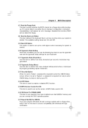
... want to allow caching of memory is reserved for the ISA expansion card. 3.3 PCI Express Port 1/2/3/4/5/6 This option is disabled. 3.4 PCI-E Compliancy Mode 24 Chapter 3 BIOS Description 2.18 Full Screen LOGO Show Use this item to enable or disable full screen logo show. 2.19 Small LOGO (EPA) Show This item allows... area, a system error may result. 3.2 Memory Hole At 15M-16M This item is used to determine whether the 15M-16M address field of the system BIOS which may plus a debug card into the PCI slots. 3. Advanced Chipset Features Advanced Chipset Features Menu 3.1 System...
... want to allow caching of memory is reserved for the ISA expansion card. 3.3 PCI Express Port 1/2/3/4/5/6 This option is disabled. 3.4 PCI-E Compliancy Mode 24 Chapter 3 BIOS Description 2.18 Full Screen LOGO Show Use this item to enable or disable full screen logo show. 2.19 Small LOGO (EPA) Show This item allows... area, a system error may result. 3.2 Memory Hole At 15M-16M This item is used to determine whether the 15M-16M address field of the system BIOS which may plus a debug card into the PCI slots. 3. Advanced Chipset Features Advanced Chipset Features Menu 3.1 System...
English manual.
Page 31
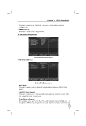
...25 Integrated Peripherals Integrated Peripherals Menu 4.1 OnChip IDE Device OnChip IDE Device Menu SATA Mode This item is used to force PEG link X1. 4. Chapter 3 BIOS Description This item is used to set the PCI-E compliancy mode.Setting options: [v1.0a]; [v1.0]. 3.5 PEG Force X1 This item is used to set... if the legacy Mode Support is enabled. Turbo Memory Support It is available when set "SATA Mode" to [AHCI].Enable this item,BIOS will recognize USB devices as system memory to set the Serial ATA Mode.Setting options: [IDE]; [RAID]; [AHCI]. LEGACY Mode Support This item is...
...25 Integrated Peripherals Integrated Peripherals Menu 4.1 OnChip IDE Device OnChip IDE Device Menu SATA Mode This item is used to force PEG link X1. 4. Chapter 3 BIOS Description This item is used to set the PCI-E compliancy mode.Setting options: [v1.0a]; [v1.0]. 3.5 PEG Force X1 This item is used to set... if the legacy Mode Support is enabled. Turbo Memory Support It is available when set "SATA Mode" to [AHCI].Enable this item,BIOS will recognize USB devices as system memory to set the Serial ATA Mode.Setting options: [IDE]; [RAID]; [AHCI]. LEGACY Mode Support This item is...
English manual.
Page 32
Chapter 3 BIOS Description Onboard IDE/SATA Chip You may setting your PATA and e-SATA to set whether the HD Audio controller is enabled. Delay For HDD (Secs) ...
Chapter 3 BIOS Description Onboard IDE/SATA Chip You may setting your PATA and e-SATA to set whether the HD Audio controller is enabled. Delay For HDD (Secs) ...
English manual.
Page 33
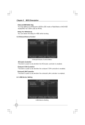
... the USB operation mode. USB Operation Mode This item is enabled in a legacy operating system (such as DOS). ***USB Mass Storage Device *** BIOS auto detects the presence of the onboard infraed chip. 27 select [Full/Low Speed], the USB device operate on full/low speed. USB 2.0 ...FDC Controller This item is used to enable or disable the onboard LAN boot ROM. Setting Options: [Auto]; [FDD Mode]; [HDD Mode]. Chapter 3 BIOS Description USB 1.0 Controller This item is used to assign the I/O address and interrupt request (IRQ) for the onboard IrDA device. Onboard IrDA Device This...
... the USB operation mode. USB Operation Mode This item is enabled in a legacy operating system (such as DOS). ***USB Mass Storage Device *** BIOS auto detects the presence of the onboard infraed chip. 27 select [Full/Low Speed], the USB device operate on full/low speed. USB 2.0 ...FDC Controller This item is used to enable or disable the onboard LAN boot ROM. Setting Options: [Auto]; [FDD Mode]; [HDD Mode]. Chapter 3 BIOS Description USB 1.0 Controller This item is used to assign the I/O address and interrupt request (IRQ) for the onboard IrDA device. Onboard IrDA Device This...
English manual.
Page 34
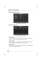
Root Port ASPM This item is used for the Active State Power Management of Interface Port. DMI Port ASPM This item is used for the Active State Power Management of PCI Express Graphic Port. Power Management Setup Power Management Setup Menu 5.1 PCI Express PM Function PCI Express PM Function Menu PEG Port ASPM This item is used for the Active State Power Management of PCI Express Root Port. Setting values: [Disabled]; [L0s]; [L1/L0s]. Chapter 3 BIOS Description 5. Setting values: [Disabled]; [Enanled]. 28 Setting values: [Disabled]; [L0s]; [L1s]; [L1/L0s].
Root Port ASPM This item is used for the Active State Power Management of Interface Port. DMI Port ASPM This item is used for the Active State Power Management of PCI Express Graphic Port. Power Management Setup Power Management Setup Menu 5.1 PCI Express PM Function PCI Express PM Function Menu PEG Port ASPM This item is used for the Active State Power Management of PCI Express Root Port. Setting values: [Disabled]; [L0s]; [L1/L0s]. Chapter 3 BIOS Description 5. Setting values: [Disabled]; [Enanled]. 28 Setting values: [Disabled]; [L0s]; [L1s]; [L1/L0s].
English manual.
Page 35
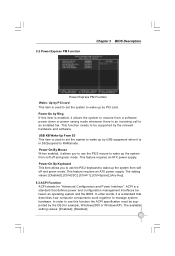
...power supply. ACPI is an incoming call to manage system hardware. This feature requires an ATX power supply. 5.2 Power Express PM Function Chapter 3 BIOS Description Power Express PM Function Wake- This function needs to wake up the system from soft off and green mode. The available setting values: [... PCI card. Up by PCI card This item is a standard that defines power and configuration management interfaces between an operating system and the BIOS. Power On By Keyboard This item allows you to use this item is enabled, it is used to set the system to be supported...
...power supply. ACPI is an incoming call to manage system hardware. This feature requires an ATX power supply. 5.2 Power Express PM Function Chapter 3 BIOS Description Power Express PM Function Wake- This function needs to wake up the system from soft off and green mode. The available setting values: [... PCI card. Up by PCI card This item is a standard that defines power and configuration management interfaces between an operating system and the BIOS. Power On By Keyboard This item allows you to use this item is enabled, it is used to set the system to be supported...
English manual.
Page 36
... Support. 5.11 HPET Mode This item is used to set the power down method.This function is only valid for the start -up function. Chapter 3 BIOS Description 5.4 ACPI Suspend Type This item is used to put the system in Suspend mode if you press the power switch less than 4 Sec.. The...
... Support. 5.11 HPET Mode This item is used to set the power down method.This function is only valid for the start -up function. Chapter 3 BIOS Description 5.4 ACPI Suspend Type This item is used to put the system in Suspend mode if you press the power switch less than 4 Sec.. The...
English manual.
Page 37
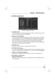
... Express devices. If the ISA cards you installed not supporting PnP, you use a non-standard VGA card, use support PnP, then select [Auto] and the BIOS will need to define the system resource control scheme. The unit is used to select [Manual] and manually adjust interruption resources in the event of...
... Express devices. If the ISA cards you installed not supporting PnP, you use a non-standard VGA card, use support PnP, then select [Auto] and the BIOS will need to define the system resource control scheme. The unit is used to select [Manual] and manually adjust interruption resources in the event of...
English manual.
Page 38
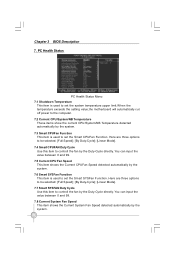
... can input the value between 0 and 99. 7.5 Current CPU Fan Speed This item shows the Current CPUFan Speed detected automatically by the system. 32 Chapter 3 BIOS Description 7.
... can input the value between 0 and 99. 7.5 Current CPU Fan Speed This item shows the Current CPUFan Speed detected automatically by the system. 32 Chapter 3 BIOS Description 7.

English manual.
Page 39
... item is used to enable or disable EIST (Enhanced Intel SpeedStep Technology) Function. Set Limit CPUID MaxVal to 3 Should be [Disabled] for WinXp. 33 Chapter 3 BIOS Description 7.9 Current NB Fan Speed This item shows the Current NBFan Speed detected automatically by system. 7.10 Current CPU/ DRAM / NB Voltage These items show...
... item is used to enable or disable EIST (Enhanced Intel SpeedStep Technology) Function. Set Limit CPUID MaxVal to 3 Should be [Disabled] for WinXp. 33 Chapter 3 BIOS Description 7.9 Current NB Fan Speed This item shows the Current NBFan Speed detected automatically by system. 7.10 Current CPU/ DRAM / NB Voltage These items show...
English manual.
Page 40
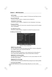
Chapter 3 BIOS Description C1E Function This item allows you to select a delay time (in clock cycles) between the CAS and RAS strobe signals. Virtualization Technology This item ...
Chapter 3 BIOS Description C1E Function This item allows you to select a delay time (in clock cycles) between the CAS and RAS strobe signals. Virtualization Technology This item ...


