English manual.
Page 4
... Introduction Main Features 2 Layout ...4 Rear I/O Ports 5 Chapter 2 Installation Instructions CPU ...7 Memory ...9 Power Supply 11 Other Connectors 12 Expansion Slots 15 Jumpers 16 Chapter 3 BIOS Description Enter BIOS Setup 18 Main menu 18 1.Standard BIOS Features 20 2.Advanced BIOS Features 22 3.Advanced Chipset Features 24 4.Integrated Peripherals 25 5.Power Management Setup 28 6.PnP/PCI Resource Management 31 7.PC Health Status 32 8.Gladiator BIOS 33 9.Load Fail-Safe Defaults 37 10.Load Optimized Defaults 37 11.Set Supervisor/ User Password 37 12.Save & Exit Setup 38...
... Introduction Main Features 2 Layout ...4 Rear I/O Ports 5 Chapter 2 Installation Instructions CPU ...7 Memory ...9 Power Supply 11 Other Connectors 12 Expansion Slots 15 Jumpers 16 Chapter 3 BIOS Description Enter BIOS Setup 18 Main menu 18 1.Standard BIOS Features 20 2.Advanced BIOS Features 22 3.Advanced Chipset Features 24 4.Integrated Peripherals 25 5.Power Management Setup 28 6.PnP/PCI Resource Management 31 7.PC Health Status 32 8.Gladiator BIOS 33 9.Load Fail-Safe Defaults 37 10.Load Optimized Defaults 37 11.Set Supervisor/ User Password 37 12.Save & Exit Setup 38...
English manual.
Page 6
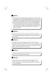
... memory module. It is turned off the DC power supply may result in serious damage to download the latest BIOS file and drivers for your system will remain consistent with the actual BIOS version at any given time in this manual are upgraded from time to time, the BIOS description in order to avoid damage to the motherboard and CPU due to select high-quality, certified fans...
... memory module. It is turned off the DC power supply may result in serious damage to download the latest BIOS file and drivers for your system will remain consistent with the actual BIOS version at any given time in this manual are upgraded from time to time, the BIOS description in order to avoid damage to the motherboard and CPU due to select high-quality, certified fans...

English manual.
Page 12
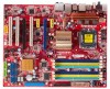
Chapter 1 Product Introduction 2 Chapter This chapter introduces the hardware installation process, including the installation of the CPU, memory, power supply, slots, pin headers, and the mounting of these modules. Please refer to the motherboard layout prior to any installation and read the contents in this chapter carefully. Caution should be exercised during the installation of jumpers. This chapter includes the following information: v CPU v Memory v Power Supply v Other Connectors v Expansion Slots v Jumpers 6
Chapter 1 Product Introduction 2 Chapter This chapter introduces the hardware installation process, including the installation of the CPU, memory, power supply, slots, pin headers, and the mounting of these modules. Please refer to the motherboard layout prior to any installation and read the contents in this chapter carefully. Caution should be exercised during the installation of jumpers. This chapter includes the following information: v CPU v Memory v Power Supply v Other Connectors v Expansion Slots v Jumpers 6
English manual.
Page 18
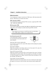
... LED is blink; Power Switch Connector (PWRSW) Attach the connector to be turned on the IDE port such as a hard disk or a CD _ROM, please configure it as a disk array through RAID controller. Front Panel Connector: FP1 1 2 + + - RESET NC 9 PWRSW Empty 10 Hard Disk LED Connector (HDD-LED) FP1! IDE Connectors: PIDE This connector support the provided Ultra DMA133/100/66 IDE hard disk ribbon cable and you install only one connector HDD_LED PLED for FDD device, IDE device,Serial ATA devices, USB devices, IR module and others. FDD Connector: FLOPPY This motherboard...
... LED is blink; Power Switch Connector (PWRSW) Attach the connector to be turned on the IDE port such as a hard disk or a CD _ROM, please configure it as a disk array through RAID controller. Front Panel Connector: FP1 1 2 + + - RESET NC 9 PWRSW Empty 10 Hard Disk LED Connector (HDD-LED) FP1! IDE Connectors: PIDE This connector support the provided Ultra DMA133/100/66 IDE hard disk ribbon cable and you install only one connector HDD_LED PLED for FDD device, IDE device,Serial ATA devices, USB devices, IR module and others. FDD Connector: FLOPPY This motherboard...
English manual.
Page 19
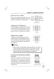
... enters S3, S4 and S5 mode. 1 GND +12V SENSE FAN1/2,NB-FAN GND SENSE 1 POWER CONTROL CPU_FAN,SYS_FAN 13 Fan Connectors: CPU_FAN,SYS_FAN,FAN1/ 2,NB _FAN There are five fan connectors on board which may connect to the front panel USB cable to either the front (provided that the front panel of the CMOS Setup. It provides two kinds of motherboards also have two 10-pin connectors on this motherboard.The fan speed...
... enters S3, S4 and S5 mode. 1 GND +12V SENSE FAN1/2,NB-FAN GND SENSE 1 POWER CONTROL CPU_FAN,SYS_FAN 13 Fan Connectors: CPU_FAN,SYS_FAN,FAN1/ 2,NB _FAN There are five fan connectors on board which may connect to the front panel USB cable to either the front (provided that the front panel of the CMOS Setup. It provides two kinds of motherboards also have two 10-pin connectors on this motherboard.The fan speed...
English manual.
Page 21
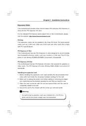
... the detailed PCI Express cards support list on this motherboard, please visit the website: http://www.foxconnchannel.com PCI Slot The expansion cards can be installed in the slot. 4. Warning: If a performance graphics card was installed into x16 PCI Express slot,24 pin power supply was recommended. 15 Align the card connector with PCI specifications. Chapter 2 Installation Instructions Expansion Slots This motherboard includes three 32-bit master PCI slots,two PCI Express x1 slots and two PCI Express x16 slots. PCI Express x1 Slot This motherboard has two PCI Express x1 slots designed...
... the detailed PCI Express cards support list on this motherboard, please visit the website: http://www.foxconnchannel.com PCI Slot The expansion cards can be installed in the slot. 4. Warning: If a performance graphics card was installed into x16 PCI Express slot,24 pin power supply was recommended. 15 Align the card connector with PCI specifications. Chapter 2 Installation Instructions Expansion Slots This motherboard includes three 32-bit master PCI slots,two PCI Express x1 slots and two PCI Express x16 slots. PCI Express x1 Slot This motherboard has two PCI Express x1 slots designed...
English manual.
Page 22
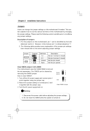
... the jumpers on this motherboard by removing the CMOS jumper. The following content carefully prior to normal (pins 2 and 3 together with the jumper cap). 3. Turn off the AC power supply and connect pins 1 and 2 together using the jumper cap. 2. Jumper 1 1 Diagram 1 1 1 1 Definition 1-2 2-3 Closed Open Description Set pin 1 and pin 2 closed Set pin 2 and pin 3 closed Set the pin closed Set the pin opened Clear CMOS Jumper: CLR_CMOS The motherboard uses the CMOS RAM to clear CMOS? 1. Return the jumper setting to modifying any jumper settings. Disconnect the power cable before...
... the jumpers on this motherboard by removing the CMOS jumper. The following content carefully prior to normal (pins 2 and 3 together with the jumper cap). 3. Turn off the AC power supply and connect pins 1 and 2 together using the jumper cap. 2. Jumper 1 1 Diagram 1 1 1 1 Definition 1-2 2-3 Closed Open Description Set pin 1 and pin 2 closed Set pin 2 and pin 3 closed Set the pin closed Set the pin opened Clear CMOS Jumper: CLR_CMOS The motherboard uses the CMOS RAM to clear CMOS? 1. Return the jumper setting to modifying any jumper settings. Disconnect the power cable before...
English manual.
Page 23
...following information: v Enter BIOS Setup v Main Menu v Standard CMOS Features v Advanced BIOS Features v Advanced Chipset Features v Integrated Peripherals v Power Management Setup v PnP/PCI Configurations v PC Health Status v Gladiator BIOS v Load Fail-Safe Defaults v Load Optimized Setting v Set Supervisor/User Password v Save & Exit Setup v Exit W ithout Saving 17 An error message appears on the screen during the system POST process. 2. You want to change the default CMOS settings. This chapter includes the following cases occur: 1. Chapter 3 BIOS Description 3 Chapter...
...following information: v Enter BIOS Setup v Main Menu v Standard CMOS Features v Advanced BIOS Features v Advanced Chipset Features v Integrated Peripherals v Power Management Setup v PnP/PCI Configurations v PC Health Status v Gladiator BIOS v Load Fail-Safe Defaults v Load Optimized Setting v Set Supervisor/User Password v Save & Exit Setup v Exit W ithout Saving 17 An error message appears on the screen during the system POST process. 2. You want to change the default CMOS settings. This chapter includes the following cases occur: 1. Chapter 3 BIOS Description 3 Chapter...
English manual.
Page 29
... Off. 2.9 Gate A20 Option This option is used to enter the CMOS Setup screen; W hen it is set up the version of MPS Table used to set to "Setup", a password is required to set up the A20 signal control necessary for system is started . Chapter 3 BIOS Description 2.7 Boot Up Floppy Seek This item controls whether the BIOS checks for this function,POST will appear an error message. Disabled this item to start up . If it...
... Off. 2.9 Gate A20 Option This option is used to enter the CMOS Setup screen; W hen it is set up the version of MPS Table used to set to "Setup", a password is required to set up the A20 signal control necessary for system is started . Chapter 3 BIOS Description 2.7 Boot Up Floppy Seek This item controls whether the BIOS checks for this function,POST will appear an error message. Disabled this item to start up . If it...
English manual.
Page 30
... system BIOS which may plus a debug card into the PCI slots. 3. Select [LPC],the onboard debug card will be available.Select [PCI],you to enable or disable the EPA logo. 2.20 Summary Screen Show This item is used to enable or disable the PCI Express port. Setting to [Auto] allows the system to allow caching of memory is reserved for the ISA expansion card. 3.3 PCI Express Port 1/2/3/4/5/6 This option is used to enable or disable the summary screen...
... system BIOS which may plus a debug card into the PCI slots. 3. Select [LPC],the onboard debug card will be available.Select [PCI],you to enable or disable the EPA logo. 2.20 Summary Screen Show This item is used to enable or disable the PCI Express port. Setting to [Auto] allows the system to allow caching of memory is reserved for the ISA expansion card. 3.3 PCI Express Port 1/2/3/4/5/6 This option is used to enable or disable the summary screen...
English manual.
Page 32
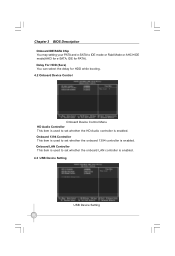
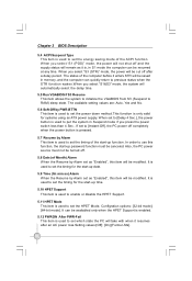
Chapter 3 BIOS Description Onboard IDE/SATA Chip You may setting your PATA and e-SATA to IDE mode or Raid Mode or AHCI+IDE mode(AHCI for e-SATA, IDE for HDD while booting. 4.2 Onboard Device Control Onboard Device Control Menu HD Audio Controller This item is used to set whether the onboard LAN controller is enabled. Onboard 1394 Controller This item is used to set whether the onboard 1394 controller is enabled. 4.3 USB Device Setting USB Device Setting 26 Onboard LAN Controller This item is used to set whether the HD Audio controller is enabled. Delay For HDD (Secs) You can select ...
Chapter 3 BIOS Description Onboard IDE/SATA Chip You may setting your PATA and e-SATA to IDE mode or Raid Mode or AHCI+IDE mode(AHCI for e-SATA, IDE for HDD while booting. 4.2 Onboard Device Control Onboard Device Control Menu HD Audio Controller This item is used to set whether the onboard LAN controller is enabled. Onboard 1394 Controller This item is used to set whether the onboard 1394 controller is enabled. 4.3 USB Device Setting USB Device Setting 26 Onboard LAN Controller This item is used to set whether the HD Audio controller is enabled. Delay For HDD (Secs) You can select ...
English manual.
Page 33
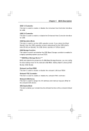
.../low speed. USB Operation Mode This item is used to set the USB operation mode. USB Storage Function This option is used to set whether the USB Mass Storage controller is enabled in a legacy operating system (such as DOS). ***USB Mass Storage Device *** BIOS auto detects the presence of the onboard infraed chip. 27 Onboard Lan Boot ROM This item is used to enable or disable the onboard FDC controller. Chapter 3 BIOS Description USB 1.0 Controller This item is used to enable or disable the Enhanced Host Controller Interface for USB. USB 2.0 Controller This...
.../low speed. USB Operation Mode This item is used to set the USB operation mode. USB Storage Function This option is used to set whether the USB Mass Storage controller is enabled in a legacy operating system (such as DOS). ***USB Mass Storage Device *** BIOS auto detects the presence of the onboard infraed chip. 27 Onboard Lan Boot ROM This item is used to enable or disable the onboard FDC controller. Chapter 3 BIOS Description USB 1.0 Controller This item is used to enable or disable the Enhanced Host Controller Interface for USB. USB 2.0 Controller This...
English manual.
Page 36
... start -up password function must not be turned off after an AC power loss.Setting values:[Off]; [On];[Former-Sts]. 30 In order to set as "Enabled", this item will be resumed at any time. Configration options: [32-bit mode]; [64-bit mode]. Also, the PC power source must be modified. It is used to set to [Instant-Off], the PC power off and the supply status...
... start -up password function must not be turned off after an AC power loss.Setting values:[Off]; [On];[Former-Sts]. 30 In order to set as "Enabled", this item will be resumed at any time. Configration options: [32-bit mode]; [64-bit mode]. Also, the PC power source must be modified. It is used to set to [Instant-Off], the PC power off and the supply status...

English manual.
Page 39
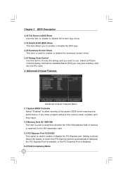
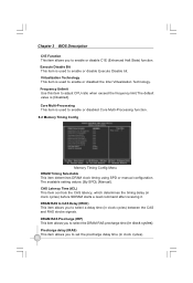
... to enable or disable CPUID maximum value limit configuration. Limit CPUID MaxVal This item is used to 3 Should be [Disabled] for WinXp. 33 Chapter 3 BIOS Description 7.9 Current NB Fan Speed This item shows the Current NBFan Speed detected automatically by system. 7.10 Current CPU/ DRAM / NB Voltage These items show the Current CPU/DRAM/NB Voltage detected automatically by the system. 7.11 Current + 5/ + 12 / + 3.3 / BAT Voltage...
... to enable or disable CPUID maximum value limit configuration. Limit CPUID MaxVal This item is used to 3 Should be [Disabled] for WinXp. 33 Chapter 3 BIOS Description 7.9 Current NB Fan Speed This item shows the Current NBFan Speed detected automatically by system. 7.10 Current CPU/ DRAM / NB Voltage These items show the Current CPU/DRAM/NB Voltage detected automatically by the system. 7.11 Current + 5/ + 12 / + 3.3 / BAT Voltage...
English manual.
Page 40
.... Frequency Unlimit Use this item to select a delay time (in clock cycles) before SDRAM starts a read command after receiving it. DRAM RAS to CAS Delay (tRCD) This item allows you to enable or disabled the Intel Virtualization Technology. DRAM RAS Precharge (tRP) This item allows you to adjust CPU ratio when exceed the frequency limit.The default value is used to enable or disable Execute Disable bit. Virtualization Technology This...
.... Frequency Unlimit Use this item to select a delay time (in clock cycles) before SDRAM starts a read command after receiving it. DRAM RAS to CAS Delay (tRCD) This item allows you to enable or disabled the Intel Virtualization Technology. DRAM RAS Precharge (tRP) This item allows you to adjust CPU ratio when exceed the frequency limit.The default value is used to enable or disable Execute Disable bit. Virtualization Technology This...
English manual.
Page 42
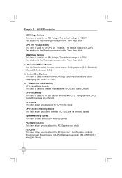
... the CPU FSB clock. PCI Express Clock This item allows you to set NB Voltage. Chapter 3 BIOS Description NB Voltage Setting This item is 1.200V. The default voltage is 1.500V. The default voltage is 1.250V. CPU Clock This item allows you to set SB Voltage. System Memory Speed This item shows the System Memory Speed. Configuration options: [Synchronous] (Synchronous with PCI Express bus clock); [33.6 MHz]; [37.3 MHz]; [42.0 MHz]. 36 CPU VTT Voltage Setting This item is used to adjust the PCI Express bus clock...
... the CPU FSB clock. PCI Express Clock This item allows you to set NB Voltage. Chapter 3 BIOS Description NB Voltage Setting This item is 1.200V. The default voltage is 1.500V. The default voltage is 1.250V. CPU Clock This item allows you to set SB Voltage. System Memory Speed This item shows the System Memory Speed. Configuration options: [Synchronous] (Synchronous with PCI Express bus clock); [33.6 MHz]; [37.3 MHz]; [42.0 MHz]. 36 CPU VTT Voltage Setting This item is used to adjust the PCI Express bus clock...

English manual.
Page 43
... may load the default to start the system. The defaults set by BIOS. Smart Boot Menu This item is used to make mistakes or not stable. Over Clock Recovery Enable this option and press Enter, it can select this option and press the key . 11. Smart Power LED This item is used to enable or disabled the smart LED. 9. Select and then press to load default. The defaults set by BIOS. The User password can be used to view the current 37 Load Optimized Defaults...
... may load the default to start the system. The defaults set by BIOS. Smart Boot Menu This item is used to make mistakes or not stable. Over Clock Recovery Enable this option and press Enter, it can select this option and press the key . 11. Smart Power LED This item is used to enable or disabled the smart LED. 9. Select and then press to load default. The defaults set by BIOS. The User password can be used to view the current 37 Load Optimized Defaults...

English manual.
Page 46
... software programs. A. Intel Chipset Driver B. Intel RAID Driver E. FOX ONE B. FOX LOGO D. The CD will automatically displays the main menu screen. 1. Create RAID Driver Floppy I. To begin using the CD, please simply insert the CD into your motherboard. Software Using these options to visit our homepage. 40 Intel RAID Utility 3. Realtek 811X LAN Driver D. A. Adobe Acrobat Reader G. Click on static FOXCONN logo to install all the drivers installed. FOX LiveUpdate C. FOX DMI E. Realtek HDA Audio Driver C. JMicron RAID Driver...
... software programs. A. Intel Chipset Driver B. Intel RAID Driver E. FOX ONE B. FOX LOGO D. The CD will automatically displays the main menu screen. 1. Create RAID Driver Floppy I. To begin using the CD, please simply insert the CD into your motherboard. Software Using these options to visit our homepage. 40 Intel RAID Utility 3. Realtek 811X LAN Driver D. A. Adobe Acrobat Reader G. Click on static FOXCONN logo to install all the drivers installed. FOX LiveUpdate C. FOX DMI E. Realtek HDA Audio Driver C. JMicron RAID Driver...
English manual.
Page 47
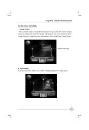
Install Utility You can select the utilities you just click"One Click Setup"button to install and begin the setup steps. 41 Install manually 2. Chapter 4 Driver CD Introduction Install driver and utility 1. Install Driver There are two ways to install drivers,manual or auto.Click the driver that you want to install and begin the steps manually.Or you want to install the driver automatically, after install Intel Chipset Driver.
Install Utility You can select the utilities you just click"One Click Setup"button to install and begin the setup steps. 41 Install manually 2. Chapter 4 Driver CD Introduction Install driver and utility 1. Install Driver There are two ways to install drivers,manual or auto.Click the driver that you want to install and begin the steps manually.Or you want to install the driver automatically, after install Intel Chipset Driver.
English manual.
Page 66
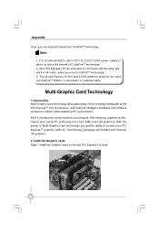
... PCI Express x16 slots. 60 Appendix Now you get the ability to connect two PCI ExpressTM graphics cards for both AMD and Intel platforms. W ith the power of the PCI ExpressTM bus architecture, and features intelligent hardware and software solutions to deliver earth-shattering PC performance. Note: 1. The all-new Radeon X1300 and X1600 graphics cards do not need a CrossFireTM Edition co-processor or external cable...
... PCI Express x16 slots. 60 Appendix Now you get the ability to connect two PCI ExpressTM graphics cards for both AMD and Intel platforms. W ith the power of the PCI ExpressTM bus architecture, and features intelligent hardware and software solutions to deliver earth-shattering PC performance. Note: 1. The all-new Radeon X1300 and X1600 graphics cards do not need a CrossFireTM Edition co-processor or external cable...


