English Manual.
Page 6
... Introduction Product Specifications 2 Layout 4 Back Panel Connectors 5 Chapter 2 Hardware Install Install the CPU and CPU Cooler 8 Install the Memory 10 Install an Expansion Card 12 Install other Internal Connectors 13 Jumpers 16 Chapter 3 BIOS Setup Enter BIOS Setup 18 Main Menu 18 System Information 20 Advanced BIOS Features 22 Fox Central Control Unit 23 Advanced Chipset Features 26 Integrated Peripherals 29 Power Management Setup 33 PC Health Status 35 BIOS Security Features 36 Load Optimal Defaults 37 Save & Exit Setup 37 Exit...
... Introduction Product Specifications 2 Layout 4 Back Panel Connectors 5 Chapter 2 Hardware Install Install the CPU and CPU Cooler 8 Install the Memory 10 Install an Expansion Card 12 Install other Internal Connectors 13 Jumpers 16 Chapter 3 BIOS Setup Enter BIOS Setup 18 Main Menu 18 System Information 20 Advanced BIOS Features 22 Fox Central Control Unit 23 Advanced Chipset Features 26 Integrated Peripherals 29 Power Management Setup 33 PC Health Status 35 BIOS Security Features 36 Load Optimal Defaults 37 Save & Exit Setup 37 Exit...
English Manual.
Page 19
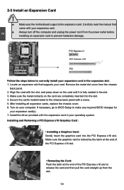
...; Installing a Graphics Card: Gently insert the graphics card into the slot. 4. Turn on the card are completely inserted into the PCI Express x16 slot. PCI Express x1 PCI Express x16 PCI Follow the steps below to make any required BIOS changes for your card. Carefully read the manual that supports your expansion card(s). 7. 2 CAUTION 2-3 Install an Expansion Card ! ■ Make sure the motherboard supports the expansion card. Locate an expansion slot that came with a screw. 5. After installing all expansion cards, replace the chassis...
...; Installing a Graphics Card: Gently insert the graphics card into the slot. 4. Turn on the card are completely inserted into the PCI Express x16 slot. PCI Express x1 PCI Express x16 PCI Follow the steps below to make any required BIOS changes for your card. Carefully read the manual that supports your expansion card(s). 7. 2 CAUTION 2-3 Install an Expansion Card ! ■ Make sure the motherboard supports the expansion card. Locate an expansion slot that came with a screw. 5. After installing all expansion cards, replace the chassis...

English Manual.
Page 21
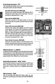
... the chassis. 2 Front Panel Connector : FP1 This motherboard includes one connector for connecting the front panel switch and LED Indicators. When the system gets into sleep mode (S1) , the LED is directional with +/- D- Hard Disk LED Connector (HDD-LED) Connect to 300MB/s data transfer rate. PWR-LED - sign. Push this product also provides two 10-pin USB headers on the front panel of the case; By connecting through USB cables with SATA Hard Disk or CD devices which support this feature. The current Serial...
... the chassis. 2 Front Panel Connector : FP1 This motherboard includes one connector for connecting the front panel switch and LED Indicators. When the system gets into sleep mode (S1) , the LED is directional with +/- D- Hard Disk LED Connector (HDD-LED) Connect to 300MB/s data transfer rate. PWR-LED - sign. Push this product also provides two 10-pin USB headers on the front panel of the case; By connecting through USB cables with SATA Hard Disk or CD devices which support this feature. The current Serial...
English Manual.
Page 23
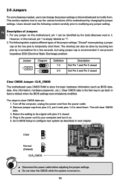
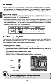
Jumper 1 Diagram 1 1 Definition 1-2 2-3 Description Set Pin 1 and Pin 2 closed Set Pin 2 and Pin 3 closed . 4. Remove jumper cap from the power outlet. 2. The following content carefully prior to its original with pins 2-3 closed Clear CMOS Jumper: CLR_CMOS The motherboard uses CMOS RAM to short them. Turn off the computer, unplug the power cord from pins 2-3, put it onto pins 1-2 to store the basic hardware information (such as BIOS data, date, time information, hardware password...etc.). 2 2-5 Jumpers For some features...
Jumper 1 Diagram 1 1 Definition 1-2 2-3 Description Set Pin 1 and Pin 2 closed Set Pin 2 and Pin 3 closed . 4. Remove jumper cap from the power outlet. 2. The following content carefully prior to its original with pins 2-3 closed Clear CMOS Jumper: CLR_CMOS The motherboard uses CMOS RAM to short them. Turn off the computer, unplug the power cord from pins 2-3, put it onto pins 1-2 to store the basic hardware information (such as BIOS data, date, time information, hardware password...etc.). 2 2-5 Jumpers For some features...
English Manual.
Page 27
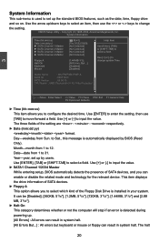
.... [All Errors But...] : All errors but keyboard or mouse or floppy can enable or disable the related mode and technology for the relevant device. Copyright (C) 1985-2006, American Megatrends, Inc. Use [ENTER] to enter the setting, then use the or keys to configure the desired time. Day-weekday from 1 to move forward a field. Month-month from Sun. Use [+] or [-] to Sat., this message is automatically displayed by users. It...
.... [All Errors But...] : All errors but keyboard or mouse or floppy can enable or disable the related mode and technology for the relevant device. Copyright (C) 1985-2006, American Megatrends, Inc. Use [ENTER] to enter the setting, then use the or keys to configure the desired time. Day-weekday from 1 to move forward a field. Month-month from Sun. Use [+] or [-] to Sat., this message is automatically displayed by users. It...
English Manual.
Page 31
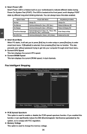
...; Memory Voltage This option is used to indicate different states during Power On System Test (POST). 3 ► Smart Power LED Smart Power LED is located at the front panel, and it can always leave this state enabled. The LED is a feature built on your computer through smart boot menu. ► Current CPU Speed This item displays the current CPU speed. ► Current DRAM Speed This item displays the current DRAM speed, in dual channels. This also prevents user without password trying to enter smart boot menu. If...
...; Memory Voltage This option is used to indicate different states during Power On System Test (POST). 3 ► Smart Power LED Smart Power LED is located at the front panel, and it can always leave this state enabled. The LED is a feature built on your computer through smart boot menu. ► Current CPU Speed This item displays the current CPU speed. ► Current DRAM Speed This item displays the current DRAM speed, in dual channels. This also prevents user without password trying to enter smart boot menu. If...
English Manual.
Page 32
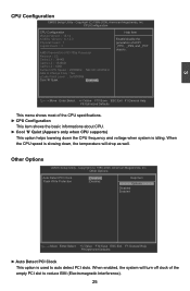
... down the CPU frequency and voltage when system is used to auto detect PCI slots. Other Options CMOS Setup Utility - CPU Configuration CPU Configuration Help Item Module Version : 14.14 AGESA Version : 6.1.3.0 Enable/disable the Physical Count : 1 generation of the empty PCI slot to Change Freq. : Yes uCode Patch Level : 0x1000086 Cool 'N' Quiet [Enabled] Move Enter:Select +/-/:Value F10:Save ESC:Exit F1:General Help F9:Optimized Defaults This menu shows most of the CPU specifications. ► CPU Configuration This...
... down the CPU frequency and voltage when system is used to auto detect PCI slots. Other Options CMOS Setup Utility - CPU Configuration CPU Configuration Help Item Module Version : 14.14 AGESA Version : 6.1.3.0 Enable/disable the Physical Count : 1 generation of the empty PCI slot to Change Freq. : Yes uCode Patch Level : 0x1000086 Cool 'N' Quiet [Enabled] Move Enter:Select +/-/:Value F10:Save ESC:Exit F1:General Help F9:Optimized Defaults This menu shows most of the CPU specifications. ► CPU Configuration This...
English Manual.
Page 37
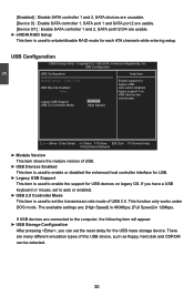
... CMOS Setup Utility - USB Configuration USB Configuration Help Item Module Version - 2.24.5-13.4 Enable support for legacy USB. USB 2.0 Controller Mode [High Speed] Move Enter:Select +/-/:Value F10:Save ESC:Exit F1:General Help F9:Optimized Defaults ► Module Version This item shows the module version of USB. ► USB Devices Enabled This item is used to enable or disabled the enhanced host controller interface for USB. ► Legacy USB Support This item is used to set the transmission rate mode of this USB device, such as floppy, hard disk...
... CMOS Setup Utility - USB Configuration USB Configuration Help Item Module Version - 2.24.5-13.4 Enable support for legacy USB. USB 2.0 Controller Mode [High Speed] Move Enter:Select +/-/:Value F10:Save ESC:Exit F1:General Help F9:Optimized Defaults ► Module Version This item shows the module version of USB. ► USB Devices Enabled This item is used to enable or disabled the enhanced host controller interface for USB. ► Legacy USB Support This item is used to set the transmission rate mode of this USB device, such as floppy, hard disk...

English Manual.
Page 39
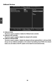
... network. 3 Onboard Devices CMOS Setup Utility - By installing a boot ROM in the network board, you set up a diskless workstation on the network to enable or disable the onboard LAN boot optional ROM. Ondoard Devices AZALIA AUDIO [Aut o] Help Item Onboard LAN Controller Onboard LAN Boot ROM [Enabled] [Disabled] Options Auto Disabled Move Enter:Select +/-/:Value F10:Save ESC:Exit F1:General Help F9:Optimized Defaults ► AZALIA AUDIO This item is used to enabled or disable the AZALIA AUDIO controller. ► OnBoard...
... network. 3 Onboard Devices CMOS Setup Utility - By installing a boot ROM in the network board, you set up a diskless workstation on the network to enable or disable the onboard LAN boot optional ROM. Ondoard Devices AZALIA AUDIO [Aut o] Help Item Onboard LAN Controller Onboard LAN Boot ROM [Enabled] [Disabled] Options Auto Disabled Move Enter:Select +/-/:Value F10:Save ESC:Exit F1:General Help F9:Optimized Defaults ► AZALIA AUDIO This item is used to enabled or disable the AZALIA AUDIO controller. ► OnBoard...

English Manual.
Page 46
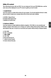
... PC screen to guide you to install. 1. Realtek HDA Audio Driver C.Realtek 811XLAN Driver 2. FOX DMI E. Norton Internet Security 39 Software Utilities Use these options to restart your computer after all the drivers for your system without going to BIOS. FOX LOGO D. 4 Utility CD content This motherboard comes with one DVD. You can simply put it into your DVD-ROM drive, and the main menu will be displayed on your system setting...
... PC screen to guide you to install. 1. Realtek HDA Audio Driver C.Realtek 811XLAN Driver 2. FOX DMI E. Norton Internet Security 39 Software Utilities Use these options to restart your computer after all the drivers for your system without going to BIOS. FOX LOGO D. 4 Utility CD content This motherboard comes with one DVD. You can simply put it into your DVD-ROM drive, and the main menu will be displayed on your system setting...
English Manual.
Page 71
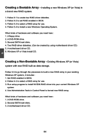
A floppy drive. 2. Set RAID enabled in Control Panel to install NVIDIA RAID driver into your existing Windows XP system, it includes : 1. Run setup program to format new RAID array. Use Administrative Tools in BIOS. 2. Installing a new Windows XP (or Vista) in BIOS. 3. A motherboard driver CD. 6. Windows XP or Vista Install CD. Existing Windows XP (or Vista) system with new RAID built as data storage. A motherboard driver CD. 64 A DVD-ROM drive. 3. Several SATA hard disks. 4. Follow 5-3 to select a RAID array for use . 3. Follow 5-3 to select a RAID array...
A floppy drive. 2. Set RAID enabled in Control Panel to install NVIDIA RAID driver into your existing Windows XP system, it includes : 1. Run setup program to format new RAID array. Use Administrative Tools in BIOS. 2. Installing a new Windows XP (or Vista) in BIOS. 3. A motherboard driver CD. 6. Windows XP or Vista Install CD. Existing Windows XP (or Vista) system with new RAID built as data storage. A motherboard driver CD. 64 A DVD-ROM drive. 3. Several SATA hard disks. 4. Follow 5-3 to select a RAID array for use . 3. Follow 5-3 to select a RAID array...
English Manual.
Page 95
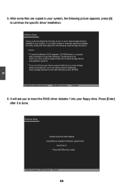
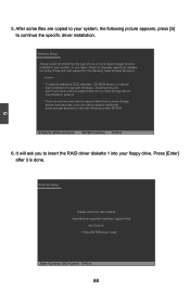
... 88 Windows Setup Please insert the disk labeled manufacturer-supplied hardware support disk into your floppy drive. After some files are copied to your system, or you do not have chosen to continue the specific driver installation. S=Specify Additional Device ENTER=Continue F3=Exit 6. It will load support for use with Windows, press ENTER. Press [Enter] after it is done. Windows Setup Setup could not determine the type of one or more mass storage devices installed in...
... 88 Windows Setup Please insert the disk labeled manufacturer-supplied hardware support disk into your floppy drive. After some files are copied to your system, or you do not have chosen to continue the specific driver installation. S=Specify Additional Device ENTER=Continue F3=Exit 6. It will load support for use with Windows, press ENTER. Press [Enter] after it is done. Windows Setup Setup could not determine the type of one or more mass storage devices installed in...
English Manual.
Page 96
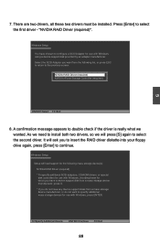
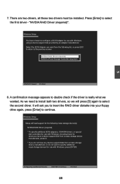
.... "NVIDIA RAID Driver (required)". As we need to the previous screen. There are two drivers, all these two drivers must be installed. S=Specify Additional Device ENTER=Continue F3=Exit 89 Windows Setup You have any device support disks from the following mass storage device(s): NVIDIA RAID Driver (required) * To specify additional SCSI adapters, CD-ROM drivers, or special disk controllers for use with Windows, including those for which you have a device support disk from a mass storage device manufacturer...
.... "NVIDIA RAID Driver (required)". As we need to the previous screen. There are two drivers, all these two drivers must be installed. S=Specify Additional Device ENTER=Continue F3=Exit 89 Windows Setup You have any device support disks from the following mass storage device(s): NVIDIA RAID Driver (required) * To specify additional SCSI adapters, CD-ROM drivers, or special disk controllers for use with Windows, including those for which you have a device support disk from a mass storage device manufacturer...

User manual
Page 19
... graphics card into the slot. 4. Make sure the metal contacts on your expansion card(s). 7. If necessary, go to BIOS Setup to the chassis back panel with the expansion card in the expansion slot. 1. After installing all expansion cards, replace the chassis cover. 6. Secure the card's metal bracket to make any required BIOS changes for your computer. Turn on the card are completely inserted into the PCI Express x16 slot. Carefully read the manual...
... graphics card into the slot. 4. Make sure the metal contacts on your expansion card(s). 7. If necessary, go to BIOS Setup to the chassis back panel with the expansion card in the expansion slot. 1. After installing all expansion cards, replace the chassis cover. 6. Secure the card's metal bracket to make any required BIOS changes for your computer. Turn on the card are completely inserted into the PCI Express x16 slot. Carefully read the manual...
User manual
Page 21
... + + HDD-LED - This 2-pin connector is directional with +/- Power Switch Connector (PWR-SW) Connect to the two USB ports on the rear panel, this product also provides two 10-pin USB headers on the front panel of the chassis. By connecting through USB cables with SATA Hard Disk or CD devices which support this switch allows the system to any IDE type of the case; This 2-pin connector is used to connect with them, user can connect to be turned on the front panel of hard disk and...
... + + HDD-LED - This 2-pin connector is directional with +/- Power Switch Connector (PWR-SW) Connect to the two USB ports on the rear panel, this product also provides two 10-pin USB headers on the front panel of the chassis. By connecting through USB cables with SATA Hard Disk or CD devices which support this switch allows the system to any IDE type of the case; This 2-pin connector is used to connect with them, user can connect to be turned on the front panel of hard disk and...
User manual
Page 23
... as "1". 2. "Closed" means placing a jumper cap on the two pins to short them . Plug in next chapter. 1 Clear 2 3 WARNING! Go to BIOS Setup to your computer and turn it onto pins 1-2 to temporarily short them . Remove jumper cap from the power outlet. 2. Return the setting to its original with pins 2-3 closed Clear CMOS Jumper: CLR_CMOS The motherboard uses CMOS RAM to factory default when the BIOS settings were mistakenly modified. The shorting can also be identified...
... as "1". 2. "Closed" means placing a jumper cap on the two pins to short them . Plug in next chapter. 1 Clear 2 3 WARNING! Go to BIOS Setup to your computer and turn it onto pins 1-2 to temporarily short them . Remove jumper cap from the power outlet. 2. Return the setting to its original with pins 2-3 closed Clear CMOS Jumper: CLR_CMOS The motherboard uses CMOS RAM to factory default when the BIOS settings were mistakenly modified. The shorting can also be identified...
User manual
Page 39
... Boot ROM [Enabled] [Disabled] Options Auto Disabled Move Enter:Select +/-/:Value F10:Save ESC:Exit F1:General Help F9:Optimized Defaults ► OnBoard Audio This item is used to enabled or disable the OnBoard Audio controller. ► OnBoard LAN Controller This item is used to enable or disable the onboard LAN controller. ► OnBoard LAN Boot ROM This item is used to be booted remotely. 32 3 OnBoard Devices CMOS Setup Utility - Copyright (C) 1985-2006, American Megatrends, Inc. By installing a boot ROM in the network board...
... Boot ROM [Enabled] [Disabled] Options Auto Disabled Move Enter:Select +/-/:Value F10:Save ESC:Exit F1:General Help F9:Optimized Defaults ► OnBoard Audio This item is used to enabled or disable the OnBoard Audio controller. ► OnBoard LAN Controller This item is used to enable or disable the onboard LAN controller. ► OnBoard LAN Boot ROM This item is used to be booted remotely. 32 3 OnBoard Devices CMOS Setup Utility - Copyright (C) 1985-2006, American Megatrends, Inc. By installing a boot ROM in the network board...
User manual
Page 46
... DVD-ROM drive, and the main menu will be displayed on your PC screen to guide you need to restart your computer after all the drivers for your system. A. Adobe Acrobat Reader G. Norton Internet Security 39 You should install the drivers in order, and you how to BIOS. Realtek HDA Audio Driver C.Realtek 811XLAN Driver 2. FOX ONE B. FOX LiveUpdate C. 4 Utility CD content This motherboard comes with one DVD...
... DVD-ROM drive, and the main menu will be displayed on your PC screen to guide you need to restart your computer after all the drivers for your system. A. Adobe Acrobat Reader G. Norton Internet Security 39 You should install the drivers in order, and you how to BIOS. Realtek HDA Audio Driver C.Realtek 811XLAN Driver 2. FOX ONE B. FOX LiveUpdate C. 4 Utility CD content This motherboard comes with one DVD...
User manual
Page 95
... insert the RAID driver diskette 1 into Drive A: * Press ENTER when ready Enter=Continue ESC=Cancel F3=Exit 88 S=Specify Additional Device ENTER=Continue F3=Exit 6. Windows Setup Please insert the disk labeled manufacturer-supplied hardware support disk into your system, the following mass storage device(s): * To specify additional SCSI adapters, CD-ROM drivers, or special disk controllers for use with Windows, press ENTER. 5 5. After some files are copied to your floppy drive. Press [Enter] after it...
... insert the RAID driver diskette 1 into Drive A: * Press ENTER when ready Enter=Continue ESC=Cancel F3=Exit 88 S=Specify Additional Device ENTER=Continue F3=Exit 6. Windows Setup Please insert the disk labeled manufacturer-supplied hardware support disk into your system, the following mass storage device(s): * To specify additional SCSI adapters, CD-ROM drivers, or special disk controllers for use with Windows, press ENTER. 5 5. After some files are copied to your floppy drive. Press [Enter] after it...
User manual
Page 96
... will load support for the following mass storage device(s): NVIDIA RAID Driver (required) * To specify additional SCSI adapters, CD-ROM drivers, or special disk controllers for use with Windows, including those for which you have a device support disk from a mass storage device manufacturer, press S. * If you want to the previous screen. NVIDIA RAID Driver (required) NVIDIA nForce Storage Controller (required) ENTER=Select F3=Exit 8. A confirmation message appears to configure a SCSI Adapter for use with Windows, press ENTER. Windows Setup Setup...
... will load support for the following mass storage device(s): NVIDIA RAID Driver (required) * To specify additional SCSI adapters, CD-ROM drivers, or special disk controllers for use with Windows, including those for which you have a device support disk from a mass storage device manufacturer, press S. * If you want to the previous screen. NVIDIA RAID Driver (required) NVIDIA nForce Storage Controller (required) ENTER=Select F3=Exit 8. A confirmation message appears to configure a SCSI Adapter for use with Windows, press ENTER. Windows Setup Setup...


