User manual
Page 11
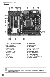
... 20. SYS_FAN Header 5. Front Panel Header 17. COM2 Header 11. Speaker Header 13. CPU_FAN Header 3. SATA 2.0 Connector 16. Front Audio Header 6. PCI Slot 9. LGA1155 CPU Socket 4. PRODUCT INTRODUCTION 1-2 Layout 98 765 4 3 2 1 10 11 12 13 14 15 20 16 17 18 19 1. 4-pin ATX 12V Power Connector 2.
... 20. SYS_FAN Header 5. Front Panel Header 17. COM2 Header 11. Speaker Header 13. CPU_FAN Header 3. SATA 2.0 Connector 16. Front Audio Header 6. PCI Slot 9. LGA1155 CPU Socket 4. PRODUCT INTRODUCTION 1-2 Layout 98 765 4 3 2 1 10 11 12 13 14 15 20 16 17 18 19 1. 4-pin ATX 12V Power Connector 2.
User manual
Page 15
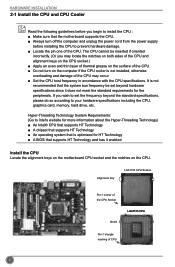
...frequency beyond hardware specifications since it enabled Install the CPU Locate the alignment keys on the motherboard CPU socket and the notches on the CPU. Alignment Key LGA1155 CPU Socket Pin-1 corner of the CPU Socket Notch LGA1155 CPU Pin-1 triangle marking of the CPU. HARDWARE INSTALLATION 2-1 Install the CPU and ... not installed, otherwise overheating and damage of the CPU may locate the notches on both sides of the CPU and alignment keys on the CPU socket.) ■ Apply an even and thin layer of thermal grease on the surface of the CPU. ■ Do not turn off the computer...
...frequency beyond hardware specifications since it enabled Install the CPU Locate the alignment keys on the motherboard CPU socket and the notches on the CPU. Alignment Key LGA1155 CPU Socket Pin-1 corner of the CPU Socket Notch LGA1155 CPU Pin-1 triangle marking of the CPU. HARDWARE INSTALLATION 2-1 Install the CPU and ... not installed, otherwise overheating and damage of the CPU may locate the notches on both sides of the CPU and alignment keys on the CPU socket.) ■ Apply an even and thin layer of thermal grease on the surface of the CPU. ■ Do not turn off the computer...

User manual
Page 16
...pin one marking (triangle) with the pin one corner of the CPU socket, align the CPU notches with the socket alignment keys and gently put the CPU onto the socket. 5. Follow the steps to install the CPU onto the CPU socket : HARDWARE INSTALLATION Before installing the CPU, make sure to turn off...unplug the power cord from the power outlet to prevent damage to its locked position. 9 Release the CPU socket lever. 2. Remove protective socket cover. 4. When CPU is properly seated, replace the metal cover and push the CPU socket lever back to the CPU. 1. Lift the metal cover on the CPU...
...pin one marking (triangle) with the pin one corner of the CPU socket, align the CPU notches with the socket alignment keys and gently put the CPU onto the socket. 5. Follow the steps to install the CPU onto the CPU socket : HARDWARE INSTALLATION Before installing the CPU, make sure to turn off...unplug the power cord from the power outlet to prevent damage to its locked position. 9 Release the CPU socket lever. 2. Remove protective socket cover. 4. When CPU is properly seated, replace the metal cover and push the CPU socket lever back to the CPU. 1. Lift the metal cover on the CPU...
User manual
Page 18
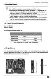
... from the power outlet before you are : DIMM1 DIMM2 Single Channel DS/SS - Follow the steps below to correctly install your memory modules into the sockets.
... from the power outlet before you are : DIMM1 DIMM2 Single Channel DS/SS - Follow the steps below to correctly install your memory modules into the sockets.

User manual
Page 19
Step 2: The clips at both ends of the socket will snap into the memory socket. Place the memory module onto the socket, then put your fingers on top edge of the module, and push it down firmly and seat it vertically into place when the memory module is securely inserted. 12 HARDWARE INSTALLATION Step 1: Spread the clips at both ends of the memory socket.
Step 2: The clips at both ends of the socket will snap into the memory socket. Place the memory module onto the socket, then put your fingers on top edge of the module, and push it down firmly and seat it vertically into place when the memory module is securely inserted. 12 HARDWARE INSTALLATION Step 1: Spread the clips at both ends of the memory socket.