
User manual
Page 1
H61MXP Series Motherboard User's Manual
H61MXP Series Motherboard User's Manual
User manual
Page 2
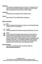
...Trademark: All trademarks are registered trademarks of this product may exist. All trade names are the property of Foxconn, Inc. WEEE: The use motherboard better, and tells you how to important information that this symbol indicates that can help prevent potential negative...product. More information: If you purchased this manual may be changed or modified at any time, Foxconn does not obligate itself to the physical motherboard for H61MXP Series motherboard. For more information about recycling of this product is the intellectual property of their respective owners....
...Trademark: All trademarks are registered trademarks of this product may exist. All trade names are the property of Foxconn, Inc. WEEE: The use motherboard better, and tells you how to important information that this symbol indicates that can help prevent potential negative...product. More information: If you purchased this manual may be changed or modified at any time, Foxconn does not obligate itself to the physical motherboard for H61MXP Series motherboard. For more information about recycling of this product is the intellectual property of their respective owners....
User manual
Page 3
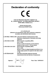
... information technology equipment ■ EN 61000-3-2/:2000 Electromagnetic compatibility (EMC) Part 3: Limits Section 2: Limits for harmonic current emissions (equipment input current declares that the product Motherboard H61MXP Series is in conformity with (reference to the specification under which conformity is declared in accordance with 89/336 EEC-EMC Directive) ■ EN 55022...
... information technology equipment ■ EN 61000-3-2/:2000 Electromagnetic compatibility (EMC) Part 3: Limits Section 2: Limits for harmonic current emissions (equipment input current declares that the product Motherboard H61MXP Series is in conformity with (reference to the specification under which conformity is declared in accordance with 89/336 EEC-EMC Directive) ■ EN 55022...
User manual
Page 4
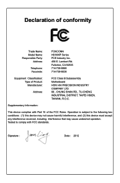
...-738-8838 Equipment Classification: Type of conformity Trade Name: Model Name: Responsible Party: Address: Telephone: Facsimile: FOXCONN H61MXP Series PCE Industry Inc. 458 E. Signature : Date : 2012 Lambert Rd. Declaration of Product: Manufacturer: Address: FCC Class B Subassembly Motherboard HON HAI PRECISION INDUSTRY COMPANY LTD 66 , CHUNG SHAN RD., TU-CHENG INDUSTRIAL DISTRICT, TAIPEI HSIEN...
...-738-8838 Equipment Classification: Type of conformity Trade Name: Model Name: Responsible Party: Address: Telephone: Facsimile: FOXCONN H61MXP Series PCE Industry Inc. 458 E. Signature : Date : 2012 Lambert Rd. Declaration of Product: Manufacturer: Address: FCC Class B Subassembly Motherboard HON HAI PRECISION INDUSTRY COMPANY LTD 66 , CHUNG SHAN RD., TU-CHENG INDUSTRIAL DISTRICT, TAIPEI HSIEN...
User manual
Page 5
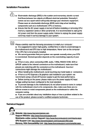
...foxconnsupport.com/cpusupportlist.aspx Memory, VGA Compatibility List: http://www.foxconnsupport.com/complist.aspx Incorrect connections might damage the motherboard. ■ When handling the motherboard, avoid touching any metal leads or connectors. ■ If there is overclocked. Also, make sure there are ...following procedures to install your device. ■ If there is suggested to select high-quality, certified fans in contact with the motherboard circuit or its components. Never turn on the power, please make sure their pinouts are uncertain about any , when connecting ...
...foxconnsupport.com/cpusupportlist.aspx Memory, VGA Compatibility List: http://www.foxconnsupport.com/complist.aspx Incorrect connections might damage the motherboard. ■ When handling the motherboard, avoid touching any metal leads or connectors. ■ If there is overclocked. Also, make sure there are ...following procedures to install your device. ■ If there is suggested to select high-quality, certified fans in contact with the motherboard circuit or its components. Never turn on the power, please make sure their pinouts are uncertain about any , when connecting ...
User manual
Page 8
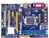
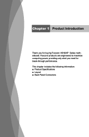
Chapter 1 Product Introduction Thank you need for buying Foxconn H61MXP Series motherboard. This chapter includes the following information: ■ Product Specifications ■ Layout ■ Back Panel Connectors Foxconn products are engineered to maximize computing power, providing only what you for break-through performance.
Chapter 1 Product Introduction Thank you need for buying Foxconn H61MXP Series motherboard. This chapter includes the following information: ■ Product Specifications ■ Layout ■ Back Panel Connectors Foxconn products are engineered to maximize computing power, providing only what you for break-through performance.
User manual
Page 11
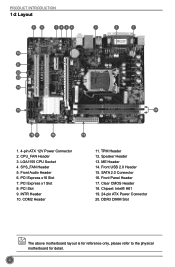
INTR Header 10. TPM Header 12. ME Header 14. SYS_FAN Header 5. COM2 Header 11. DDR3 DIMM Slot The above motherboard layout is for reference only, please refer to the physical motherboard for detail. 4 SATA 2.0 Connector 16. Front Audio Header 6. Speaker Header 13. Front USB 2.0 Header 15. Chipset: Intel® H61 19. 24-pin...
INTR Header 10. TPM Header 12. ME Header 14. SYS_FAN Header 5. COM2 Header 11. DDR3 DIMM Slot The above motherboard layout is for reference only, please refer to the physical motherboard for detail. 4 SATA 2.0 Connector 16. Front Audio Header 6. Speaker Header 13. Front USB 2.0 Header 15. Chipset: Intel® H61 19. 24-pin...
User manual
Page 14
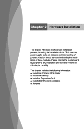
... ■ Install an Expansion Card ■ Install other Internal Connectors ■ Jumpers Caution should be exercised during the installation of jumpers. Please refer to the motherboard layout prior to any installation and read the contents in this chapter carefully. Chapter 2 Hardware Installation This chapter introduces the hardware installation process, including the...
... ■ Install an Expansion Card ■ Install other Internal Connectors ■ Jumpers Caution should be exercised during the installation of jumpers. Please refer to the motherboard layout prior to any installation and read the contents in this chapter carefully. Chapter 2 Hardware Installation This chapter introduces the hardware installation process, including the...
User manual
Page 15
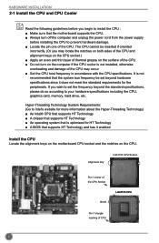
... drive, etc. The CPU cannot be set the frequency beyond hardware specifications since it enabled Install the CPU Locate the alignment keys on the motherboard CPU socket and the notches on the surface of the CPU. ■ Do not turn off the computer and unplug the power cord from.... HARDWARE INSTALLATION 2-1 Install the CPU and CPU Cooler Read the following guidelines before you begin to install the CPU : ■ Make sure that the motherboard supports the CPU. ■ Always turn on the computer if the CPU cooler is optimized for HT Technology ■ A BIOS that supports HT Technology...
... drive, etc. The CPU cannot be set the frequency beyond hardware specifications since it enabled Install the CPU Locate the alignment keys on the motherboard CPU socket and the notches on the surface of the CPU. ■ Do not turn off the computer and unplug the power cord from.... HARDWARE INSTALLATION 2-1 Install the CPU and CPU Cooler Read the following guidelines before you begin to install the CPU : ■ Make sure that the motherboard supports the CPU. ■ Always turn on the computer if the CPU cooler is optimized for HT Technology ■ A BIOS that supports HT Technology...
User manual
Page 17
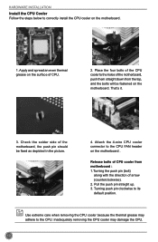
... Cooler Follow the steps below to its default position. Apply and spread an even thermal grease on the surface of the motherboard, the push pin should be fastened on the motherboard. That's it. 3. Check the solder side of CPU. 2. Pull the push pin straight up. 3. Place the four ...bolts of the CPU cooler to the holes of arrow (counterclockwise). 2. Turning push pin clockwise to correctly install the CPU cooler on the motherboard . Use extreme care when removing the CPU cooler because the thermal grease may damage the CPU. 10 Inadequately removing the CPU cooler may adhere...
... Cooler Follow the steps below to its default position. Apply and spread an even thermal grease on the surface of the motherboard, the push pin should be fastened on the motherboard. That's it. 3. Check the solder side of CPU. 2. Pull the push pin straight up. 3. Place the four ...bolts of the CPU cooler to the holes of arrow (counterclockwise). 2. Turning push pin clockwise to correctly install the CPU cooler on the motherboard . Use extreme care when removing the CPU cooler because the thermal grease may damage the CPU. 10 Inadequately removing the CPU cooler may adhere...
User manual
Page 18
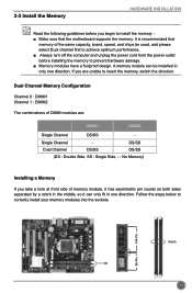
... are : DIMM1 DIMM2 Single Channel DS/SS - Follow the steps below to correctly install your memory modules into the sockets. It is recommended that the motherboard supports the memory. Notch 144-Pin 96-Pin 11 Dual Channel Memory Configuration Channel 0 : DIMM1 Channel 1 : DIMM2 The combinations of DIMM modules are unable to...
... are : DIMM1 DIMM2 Single Channel DS/SS - Follow the steps below to correctly install your memory modules into the sockets. It is recommended that the motherboard supports the memory. Notch 144-Pin 96-Pin 11 Dual Channel Memory Configuration Channel 0 : DIMM1 Channel 1 : DIMM2 The combinations of DIMM modules are unable to...
User manual
Page 20
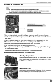
... the driver provided with a screw. 5. If necessary, go to BIOS Setup to prevent hardware damage. 2-3 Install an Expansion Card HARDWARE INSTALLATION ■ Make sure the motherboard supports the expansion card. ■ Always turn off the computer and unplug the power cord from the power outlet before installing an expansion card to...
... the driver provided with a screw. 5. If necessary, go to BIOS Setup to prevent hardware damage. 2-3 Install an Expansion Card HARDWARE INSTALLATION ■ Make sure the motherboard supports the expansion card. ■ Always turn off the computer and unplug the power cord from the power outlet before installing an expansion card to...
User manual
Page 21
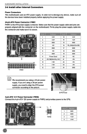
...order not to the CPU. 31 4 2 PWR2 Pin # 1 2 3 4 Definition GND GND +12V +12V 14 HARDWARE INSTALLATION 2-4 Install other Internal Connectors Power Connectors This motherboard uses an ATX power supply. Pin # Definition Pin # Definition 1 3.3V 13 3.3V 2 3.3V 14 -12V 3 GND 15 GND 4 +5V 16 PS_ON(Soft On/Off...GND 12 PWR1 1 Pin No. 24 We recommend you using a 20-pin power supply, you are properly aligned with the connector on the motherboard. If you need to align the ATX power connector according to the picture. 20-Pin Power 4-pin ATX 12 V Power Connector: PWR2 ...
...order not to the CPU. 31 4 2 PWR2 Pin # 1 2 3 4 Definition GND GND +12V +12V 14 HARDWARE INSTALLATION 2-4 Install other Internal Connectors Power Connectors This motherboard uses an ATX power supply. Pin # Definition Pin # Definition 1 3.3V 13 3.3V 2 3.3V 14 -12V 3 GND 15 GND 4 +5V 16 PS_ON(Soft On/Off...GND 12 PWR1 1 Pin No. 24 We recommend you using a 20-pin power supply, you are properly aligned with the connector on the motherboard. If you need to align the ATX power connector according to the picture. 20-Pin Power 4-pin ATX 12 V Power Connector: PWR2 ...
User manual
Page 22
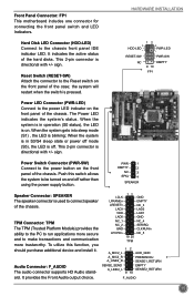
Front Panel Connector: FP1 This motherboard includes one connector for connecting the front panel switch and LED Indicators. sign. the system will restart when the switch is blinking; Power Switch Connector (...
Front Panel Connector: FP1 This motherboard includes one connector for connecting the front panel switch and LED Indicators. sign. the system will restart when the switch is blinking; Power Switch Connector (...
User manual
Page 23
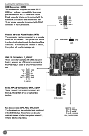
...: F_USB1/2 These connectors comply with USB 2.0 speci- Fan Connectors: CPU_FAN, SYS_FAN1 The fan speed can be controlled and monitored in the motherboard. These fans can be automatically turned off after the system enters S3, S4 and S5 sleeping states. User must purchase another end with 10...-pin female connector to connect with COM1 connector in the BIOS Setup. HARDWARE INSTALLATION COM Connector : COM2 This motherboard supports one end to connect with the external RS232 device and another RS232 cable with a 9-pin D-sub connector at one serial RS232...
...: F_USB1/2 These connectors comply with USB 2.0 speci- Fan Connectors: CPU_FAN, SYS_FAN1 The fan speed can be controlled and monitored in the motherboard. These fans can be automatically turned off after the system enters S3, S4 and S5 sleeping states. User must purchase another end with 10...-pin female connector to connect with COM1 connector in the BIOS Setup. HARDWARE INSTALLATION COM Connector : COM2 This motherboard supports one end to connect with the external RS232 device and another RS232 cable with a 9-pin D-sub connector at one serial RS232...
User manual
Page 24
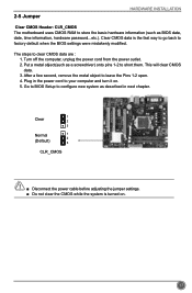
..., date, time information, hardware password...etc.). This will clear CMOS data. 3. Clear CMOS data is turned on . 5. 2-5 Jumper HARDWARE INSTALLATION Clear CMOS Header: CLR_CMOS The motherboard uses CMOS RAM to your computer and turn it on .
..., date, time information, hardware password...etc.). This will clear CMOS data. 3. Clear CMOS data is turned on . 5. 2-5 Jumper HARDWARE INSTALLATION Clear CMOS Header: CLR_CMOS The motherboard uses CMOS RAM to your computer and turn it on .
User manual
Page 25
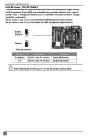
... Engine function. CAUTION 18 Intel® Management Engine (ME) is an embedded microcontroller located in Intel chipset. HARDWARE INSTALLATION Intel® ME Jumper: PCH_ME_ENABLE This motherboard uses this jumper to improve management of corporate assets.
... Engine function. CAUTION 18 Intel® Management Engine (ME) is an embedded microcontroller located in Intel chipset. HARDWARE INSTALLATION Intel® ME Jumper: PCH_ME_ENABLE This motherboard uses this jumper to improve management of corporate assets.
User manual
Page 31
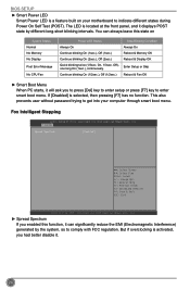
... Boot Menu When PC starts, it will ask you had better disable it. 24 This also prevents user without password trying to get into your motherboard to indicate different states during Power On Self Test (POST). Fox Intelligent Stepping Aptio Setup Utility - Copyright (C) 2012 American Megatrends, Inc. ► Spread Spectrum If...
... Boot Menu When PC starts, it will ask you had better disable it. 24 This also prevents user without password trying to get into your motherboard to indicate different states during Power On Self Test (POST). Fox Intelligent Stepping Aptio Setup Utility - Copyright (C) 2012 American Megatrends, Inc. ► Spread Spectrum If...
User manual
Page 33
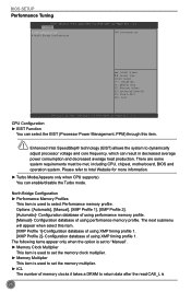
.... ► tCL The number of using XMP timing profile 1. Copyright (C) 2012 American Megatrends, Inc. There are some system requirements must be met, including CPU, chipset, motherboard, BIOS and operation system. C opyright (C) 2012 American Megatrends, Inc. CPU Configuration ► EIST Function You can enable/disable the Turbo mode. Configuration database of memory...
.... ► tCL The number of using XMP timing profile 1. Copyright (C) 2012 American Megatrends, Inc. There are some system requirements must be met, including CPU, chipset, motherboard, BIOS and operation system. C opyright (C) 2012 American Megatrends, Inc. CPU Configuration ► EIST Function You can enable/disable the Turbo mode. Configuration database of memory...
User manual
Page 38
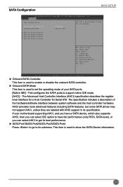
... features, but some SATA drives may not support AHCI, unless they are labeled with AHCI support in its submenu. The specification includes a description of your motherboard supporting AHCI, and you have a SATA device, which also supports AHCI, then you can select IDE option to have fair performance (only PATA, SATA level...
... features, but some SATA drives may not support AHCI, unless they are labeled with AHCI support in its submenu. The specification includes a description of your motherboard supporting AHCI, and you have a SATA device, which also supports AHCI, then you can select IDE option to have fair performance (only PATA, SATA level...


