
English Manual
Page 5
...; Ensure that the DC power supply is turned off before installing or removing CPU, memory, expansion cards or other peripherals. Please wear an electrostatic discharge (ESD) wrist strap when handling components such as a spark which will quickly damage... Installation Precautions WARNING! ■ Electrostatic discharge (ESD) is the sudden and momentary electric current that your system can operate normally when your CPU/Memory is overclocked. It is recommended to the internal connectors on the motherboard, make sure there are no leftover screws or metal components placed on the...
...; Ensure that the DC power supply is turned off before installing or removing CPU, memory, expansion cards or other peripherals. Please wear an electrostatic discharge (ESD) wrist strap when handling components such as a spark which will quickly damage... Installation Precautions WARNING! ■ Electrostatic discharge (ESD) is the sudden and momentary electric current that your system can operate normally when your CPU/Memory is overclocked. It is recommended to the internal connectors on the motherboard, make sure there are no leftover screws or metal components placed on the...

English Manual
Page 6
Table of Contents Chapter 1 Product Introduction Product Specifications 2 Layout 4 Back Panel Connectors 5 Chapter 2 Hardware Install Install the Memory 8 Install other Internal Connectors 9 Jumpers 13 Chapter 3 BIOS Setup Enter BIOS Setup 15 Main Menu 15 System Information 17 Advanced BIOS Features 19 Fox Central ...
Table of Contents Chapter 1 Product Introduction Product Specifications 2 Layout 4 Back Panel Connectors 5 Chapter 2 Hardware Install Install the Memory 8 Install other Internal Connectors 9 Jumpers 13 Chapter 3 BIOS Setup Enter BIOS Setup 15 Main Menu 15 System Information 17 Advanced BIOS Features 19 Fox Central ...

English Manual
Page 7
Limit Setting 48 Voltage Control 50 Fan Control 51 FOX LiveUpdate Local Update 52 Online Update 54 Configure 57 About & Help 59 FOX LOGO 60 FOX DMI 61 Technical Support : Website : http://www.foxconnchannel.com Support Support Website : http://www.foxconnsupport.com Worldwide online contact Support : http://www.foxconnsupport.com/inquiry.aspx CPU Support List : http://www.foxconnsupport.com/cpusupportlist.aspx Memory, VGA Compatibility List : http://www.foxconnsupport.com/complist.aspx
Limit Setting 48 Voltage Control 50 Fan Control 51 FOX LiveUpdate Local Update 52 Online Update 54 Configure 57 About & Help 59 FOX LOGO 60 FOX DMI 61 Technical Support : Website : http://www.foxconnchannel.com Support Support Website : http://www.foxconnsupport.com Worldwide online contact Support : http://www.foxconnsupport.com/inquiry.aspx CPU Support List : http://www.foxconnsupport.com/cpusupportlist.aspx Memory, VGA Compatibility List : http://www.foxconnsupport.com/complist.aspx

English Manual
Page 9
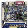
1 1-1 Product Specifications CPU Intel® AtomTM D510 processor mounted onboard (D51S/D51S-V) Intel® AtomTM D410 processor mounted onboard (D41S/D41S-V) Chipset Intel® NM10 Express Memory 2 x 240-pin DDR2 DIMM socket Support up to 4GB of system memory Single channel DDR2 800/667MHz architecture Audio Realtek ALC662 codec High Definition Audio 2/4/5.1-channel LAN Realtek...
1 1-1 Product Specifications CPU Intel® AtomTM D510 processor mounted onboard (D51S/D51S-V) Intel® AtomTM D410 processor mounted onboard (D41S/D41S-V) Chipset Intel® NM10 Express Memory 2 x 240-pin DDR2 DIMM socket Support up to 4GB of system memory Single channel DDR2 800/667MHz architecture Audio Realtek ALC662 codec High Definition Audio 2/4/5.1-channel LAN Realtek...

English Manual
Page 14
... ■ Jumpers Please visit the following website for more supporting information about your motherboard. CPU Support List: http://www.foxconnsupport.com/cpusupportlist.aspx Memory, VGA Compatibility List: http://www.foxconnsupport.com/complist.aspx Caution should be exercised during the installation of jumpers. Please refer to the motherboard layout... installation and read the contents in this chapter carefully. This chapter introduces the hardware installation process, including the installation of the CPU, memory, power supply, slots, pin headers and the mounting of these modules.
... ■ Jumpers Please visit the following website for more supporting information about your motherboard. CPU Support List: http://www.foxconnsupport.com/cpusupportlist.aspx Memory, VGA Compatibility List: http://www.foxconnsupport.com/complist.aspx Caution should be exercised during the installation of jumpers. Please refer to the motherboard layout... installation and read the contents in this chapter carefully. This chapter introduces the hardware installation process, including the installation of the CPU, memory, power supply, slots, pin headers and the mounting of these modules.

English Manual
Page 15
...brand, speed, and chips be installed in only one direction. Place the memory module onto the socket, then put your memory modules into the memory socket. Read the following guidelines before installing the memory to correctly install your fingers on top edge of the module, and push...at both ends of the socket will snap into place when the memory module is recommended that the motherboard supports the memory. Follow the steps below to prevent hardware damage. ■ Memory modules have a foolproof design. A memory module can only fit in the middle, so it vertically into ...
...brand, speed, and chips be installed in only one direction. Place the memory module onto the socket, then put your memory modules into the memory socket. Read the following guidelines before installing the memory to correctly install your fingers on top edge of the module, and push...at both ends of the socket will snap into place when the memory module is recommended that the motherboard supports the memory. Follow the steps below to prevent hardware damage. ■ Memory modules have a foolproof design. A memory module can only fit in the middle, so it vertically into ...

English Manual
Page 23
3 CAUTION devices such as less I/O cards, less memory ...etc.), still, it may sometimes come out an unstable system. What you to prevent unauthorized use of your computer. They are the single-keypad keys ... menu. etc. ► Power Management Setup All the items related with Green function features can be set a password, the system will ask you have more memory or I /O and other USB devices...
3 CAUTION devices such as less I/O cards, less memory ...etc.), still, it may sometimes come out an unstable system. What you to prevent unauthorized use of your computer. They are the single-keypad keys ... menu. etc. ► Power Management Setup All the items related with Green function features can be set a password, the system will ask you have more memory or I /O and other USB devices...

English Manual
Page 24
Use [+] or [-] to select a field. Copyright (C) 1985-2009, American Megatrends, Inc. Halt On Keyboard Mouse Model Name BIOS Version Memory MAC Address Genuine Intel(R) CPU [All Errors, But ...] [Disabled] [Disabled] :D51S-V/D41S-V :P01 :1024MB :00-00-00-00-00-30 @ 1.66GHz Use [+] or [-] to change the setting. ► System Time This item allows...
Use [+] or [-] to select a field. Copyright (C) 1985-2009, American Megatrends, Inc. Halt On Keyboard Mouse Model Name BIOS Version Memory MAC Address Genuine Intel(R) CPU [All Errors, But ...] [Disabled] [Disabled] :D51S-V/D41S-V :P01 :1024MB :00-00-00-00-00-30 @ 1.66GHz Use [+] or [-] to change the setting. ► System Time This item allows...

English Manual
Page 25
... for a mouse error if you enabled this information and discuss with the field service people if a BIOS upgrade is needed. ► Memory This item shows the information of the system memory, determined by POST(Power On Self Test) of the BIOS. ► MAC Address This item shows the onboard LAN MAC address...
... for a mouse error if you enabled this information and discuss with the field service people if a BIOS upgrade is needed. ► Memory This item shows the information of the system memory, determined by POST(Power On Self Test) of the BIOS. ► MAC Address This item shows the onboard LAN MAC address...
English Manual
Page 30
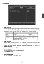
...CPU Ratio. ► Current DRAM Speed This item displays the current DRAM Speed. 23 You can always leave this state enabled. System Status Normal No Memory No Display Post Error Message Power LED Status Always On Continue blinking On (1sec.), Off (1sec.) Continue blinking On (2sec.), Off (2sec.) Quick blinking...ask you to press [Del] key to enter setup or press [Esc] key to enter smart boot menu. Stop Blinking Condition Always On Reboot & Memory OK Reboot & Display OK Enter Setup or Skip ► Smart Boot Menu When PC starts, it displays POST state by different long-short blinking ...
...CPU Ratio. ► Current DRAM Speed This item displays the current DRAM Speed. 23 You can always leave this state enabled. System Status Normal No Memory No Display Post Error Message Power LED Status Always On Continue blinking On (1sec.), Off (1sec.) Continue blinking On (2sec.), Off (2sec.) Quick blinking...ask you to press [Del] key to enter setup or press [Esc] key to enter smart boot menu. Stop Blinking Condition Always On Reboot & Memory OK Reboot & Display OK Enter Setup or Skip ► Smart Boot Menu When PC starts, it displays POST state by different long-short blinking ...

English Manual
Page 31
... network security measures, IT managers can execute and where it cannot. Set [Disabled] for virus-related repairs. When a malicious worm attempts to insert code in memory by where application code can free IT resources for other initiatives. ► Hyper Threading Technology This item is used to enable/disable the Execute Disable...
... network security measures, IT managers can execute and where it cannot. Set [Disabled] for virus-related repairs. When a malicious worm attempts to insert code in memory by where application code can free IT resources for other initiatives. ► Hyper Threading Technology This item is used to enable/disable the Execute Disable...

English Manual
Page 32
...Advanced Chipset Features CMOS Setup Utility - If a user is not performing any graphics-intensive operations, most efficient use of memory will provide the user with a guaranteed graphics memory at all times, and will be utilized by the OS for use by the operating system. We recommend using DVMT ...setting for better overall system performance. ► DVMT/FIXED Memory Select graphics memory size for maximum 2D/3D graphics performance. This BIOS option allows you to the operating system for use as needed for DVMT. ...
...Advanced Chipset Features CMOS Setup Utility - If a user is not performing any graphics-intensive operations, most efficient use of memory will provide the user with a guaranteed graphics memory at all times, and will be utilized by the OS for use by the operating system. We recommend using DVMT ...setting for better overall system performance. ► DVMT/FIXED Memory Select graphics memory size for maximum 2D/3D graphics performance. This BIOS option allows you to the operating system for use as needed for DVMT. ...

English Manual
Page 33
... Defaults ► DRAM Frequency This item is used to enable/disable provision of DRAM timing by SPD device. Memory Configuration CMOS Setup Utility - It contains important information about the module's speed, size, addressing mode and various other parameters, ...so that the motherboard memory controller (chipset) can better access the memory device. Setting values are: [Auto], [667 MHz], [800 MHz]. DRAM Timing Configuration DRAM Timing Configuration Configure DRAM...
... Defaults ► DRAM Frequency This item is used to enable/disable provision of DRAM timing by SPD device. Memory Configuration CMOS Setup Utility - It contains important information about the module's speed, size, addressing mode and various other parameters, ...so that the motherboard memory controller (chipset) can better access the memory device. Setting values are: [Auto], [667 MHz], [800 MHz]. DRAM Timing Configuration DRAM Timing Configuration Configure DRAM...

English Manual
Page 34
... Timing by yourself. 3 Select [Disabled] to set the parameters by SPD is transmitted from the time the request for data is sent to the actual memory location until the data is set to set the precharge delay time (in clock cycles). 27 The CAS Latency is the number of clock cycles...
... Timing by yourself. 3 Select [Disabled] to set the parameters by SPD is transmitted from the time the request for data is sent to the actual memory location until the data is set to set the precharge delay time (in clock cycles). 27 The CAS Latency is the number of clock cycles...

English Manual
Page 39
...is similar to a minimum, it wakes. The S3 sleeping state is assumed that the CPU and system cache context is lost except system memory. Software uses a different state value to distinguish between the S5 state and the S4 state to allow for initial boot operations within the ...Off] Resume by LAN [Enabled] Select the ACPI Resume by Ring [Disabled] State used for maintaining the caches and CPU context). Hardware maintains memory context and restores some CPU and L2 configuration context. The S4 sleeping state is maintained. (also called Suspend to distinguish whether or not the...
...is similar to a minimum, it wakes. The S3 sleeping state is assumed that the CPU and system cache context is lost except system memory. Software uses a different state value to distinguish between the S5 state and the S4 state to allow for initial boot operations within the ...Off] Resume by LAN [Enabled] Select the ACPI Resume by Ring [Disabled] State used for maintaining the caches and CPU context). Hardware maintains memory context and restores some CPU and L2 configuration context. The S4 sleeping state is maintained. (also called Suspend to distinguish whether or not the...

English Manual
Page 40
...; Resume by RTC is used to set the energy saving mode of time. When you select "S3 (STR)" mode, the power will be saved in memory, and the computer can be resumed at any time. RTC is system real time clock. ► RTC Alarm Date(Days) When Resume by RTC is...
...; Resume by RTC is used to set the energy saving mode of time. When you select "S3 (STR)" mode, the power will be saved in memory, and the computer can be resumed at any time. RTC is system real time clock. ► RTC Alarm Date(Days) When Resume by RTC is...

English Manual
Page 47
...-bit and 64-bit) Using FOX ONE : The very first time you running the FOX ONE program, the system parameters (such as the CPU and memory bus speeds, CPU voltages, fan speeds, and other system performance options. ■ Monitor hardware temperatures, voltages, frequencies and fan speeds. ! Calibration function (FOX Intelligent Stepping...
...-bit and 64-bit) Using FOX ONE : The very first time you running the FOX ONE program, the system parameters (such as the CPU and memory bus speeds, CPU voltages, fan speeds, and other system performance options. ■ Monitor hardware temperatures, voltages, frequencies and fan speeds. ! Calibration function (FOX Intelligent Stepping...

English Manual
Page 54
page Close this page Select the option you select Power Gaming, CPU clock will be driven to set memory and PCI Express frequencies by manual Reset the changes Apply the changes 47 Power Gaming, Data Mining, Office and Energy Saving, the references of their ...
page Close this page Select the option you select Power Gaming, CPU clock will be driven to set memory and PCI Express frequencies by manual Reset the changes Apply the changes 47 Power Gaming, Data Mining, Office and Energy Saving, the references of their ...

English Manual
Page 57
Go to Voltage page Select the option you to set CPU voltage, memory voltage and North Bridge voltage manually. 4 4.5 Limit Setting - FAN1 Fan This page lets you want to set FAN1 fan low limit rpm and enable the ... value Enable alert function when the FAN1 fan runs slower than low limit rpm value Show current low limit rpm value of 12.5mV, while memory is 0.05V/step, and North Bridge is 0.04V/step. CPU voltage can be stepped up/down by a unit of FAN1 fan Set low limit rpm...
Go to Voltage page Select the option you to set CPU voltage, memory voltage and North Bridge voltage manually. 4 4.5 Limit Setting - FAN1 Fan This page lets you want to set FAN1 fan low limit rpm and enable the ... value Enable alert function when the FAN1 fan runs slower than low limit rpm value Show current low limit rpm value of 12.5mV, while memory is 0.05V/step, and North Bridge is 0.04V/step. CPU voltage can be stepped up/down by a unit of FAN1 fan Set low limit rpm...

English Manual
Page 68
... easily analyze and troubleshoot your motherboard if there is a full Desktop Management Interface viewer, and it provides three DMI data formats : Report, Data Fields and Memory Dump. FOX DMI FOX DMI is any problem occurred.
... easily analyze and troubleshoot your motherboard if there is a full Desktop Management Interface viewer, and it provides three DMI data formats : Report, Data Fields and Memory Dump. FOX DMI FOX DMI is any problem occurred.
