User Manual
Page 1
All product names are subject to change without notice. Specifications are trademarks of their respective companies. 9040 Phase Rotation Indicator Users Manual PN 2438546 April 2005, Rev.2, 5/11 © 2005-2011 Fluke Corporation. All rights reserved.
All product names are subject to change without notice. Specifications are trademarks of their respective companies. 9040 Phase Rotation Indicator Users Manual PN 2438546 April 2005, Rev.2, 5/11 © 2005-2011 Fluke Corporation. All rights reserved.
User Manual
Page 2
... the warranty period, contact your nearest Fluke authorized service center to obtain return authorization information, then send the product to that Service Center with a description of liability may not apply to extend any other warranty on Fluke's behalf. NO OTHER WARRANTIES, SUCH AS FITNESS FOR... or of incidental or consequential damages, this limitation of the problem. Box 9090 Everett, WA 98206-9090 U.S.A. P.O. Fluke Corporation P.O. THIS WARRANTY IS YOUR ONLY REMEDY. This warranty does not cover fuses, disposable batteries, or damage from the date of purchase. Resellers are not...
... the warranty period, contact your nearest Fluke authorized service center to obtain return authorization information, then send the product to that Service Center with a description of liability may not apply to extend any other warranty on Fluke's behalf. NO OTHER WARRANTIES, SUCH AS FITNESS FOR... or of incidental or consequential damages, this limitation of the problem. Box 9090 Everett, WA 98206-9090 U.S.A. P.O. Fluke Corporation P.O. THIS WARRANTY IS YOUR ONLY REMEDY. This warranty does not cover fuses, disposable batteries, or damage from the date of purchase. Resellers are not...
User Manual
Page 3
Table of Contents Title Page Introduction...1 Contacting Fluke 1 Unpacking the 9040 2 Safety Information 3 Symbols...5 Elements of the 9040 6 Determine the Rotary Field Direction 7 Maintaining the 9040 8 Replacing the Fuse (9040UK only 9 Specifications ...10 i
Table of Contents Title Page Introduction...1 Contacting Fluke 1 Unpacking the 9040 2 Safety Information 3 Symbols...5 Elements of the 9040 6 Determine the Rotary Field Direction 7 Maintaining the 9040 8 Replacing the Fuse (9040UK only 9 Specifications ...10 i
User Manual
Page 5
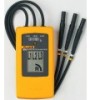
... view, print, or download the latest manual supplement, visit http://us.fluke.com/usen/support/manuals. 1 9040 Introduction The Fluke 9040 Phase Rotation Indicator (the 9040) is a handheld instrument designed to detect the rotary field of three-phase systems. How to Contact Fluke To contact Fluke, call one of the following telephone numbers: • Technical Support USA: 1-800-44-FLUKE (1-800-443-5853) • Calibration/Repair USA...
... view, print, or download the latest manual supplement, visit http://us.fluke.com/usen/support/manuals. 1 9040 Introduction The Fluke 9040 Phase Rotation Indicator (the 9040) is a handheld instrument designed to detect the rotary field of three-phase systems. How to Contact Fluke To contact Fluke, call one of the following telephone numbers: • Technical Support USA: 1-800-44-FLUKE (1-800-443-5853) • Calibration/Repair USA...
User Manual
Page 6
... on your purchase, the 9040 ships with these items: • 9040 o 3 self-retaining test probes, 1000 V CAT II o 3 alligator clips, 1000 V CAT III/600 V CAT IV o Users Manual • 9040UK o 3 fused test probes, 1000 V CAT III o 3 alligator clips, 1000 V CAT III/600 V CAT IV o Users Manual • 9040EUR o 3 Slim-Reach™ test probes (black) 1000 V CAT III/600...
... on your purchase, the 9040 ships with these items: • 9040 o 3 self-retaining test probes, 1000 V CAT II o 3 alligator clips, 1000 V CAT III/600 V CAT IV o Users Manual • 9040UK o 3 fused test probes, 1000 V CAT III o 3 alligator clips, 1000 V CAT III/600 V CAT IV o Users Manual • 9040EUR o 3 Slim-Reach™ test probes (black) 1000 V CAT III/600...
User Manual
Page 7
...prevent possible electrical shock, fire, or personal injury: • Carefully read all instructions. • Comply with local and national safety codes. Examine the test leads for damaged insulation or exposed metal. Check test lead...Use the product only as specified, or the protection supplied by the product can be compromised. • Do not work alone. • Do not use test leads if they are damaged. Use personal protective equipment (approved rubber gloves, face protection, and flameresistant clothes) to the user. Warning identifies conditions and actions that may damage the 9040...
...prevent possible electrical shock, fire, or personal injury: • Carefully read all instructions. • Comply with local and national safety codes. Examine the test leads for damaged insulation or exposed metal. Check test lead...Use the product only as specified, or the protection supplied by the product can be compromised. • Do not work alone. • Do not use test leads if they are damaged. Use personal protective equipment (approved rubber gloves, face protection, and flameresistant clothes) to the user. Warning identifies conditions and actions that may damage the 9040...
User Manual
Page 8
9040 Users Manual • Measurements can be adversely affected by impedances of additional operating circuits connected in parallel or by transient currents. • Verify operation prior to measuring hazardous voltages (voltages above 30 V ac rms, 42 V ac peak and 60 V dc). • Do not use the 9040 with any of the parts removed. • Do not use the product around explosive gas, vapor, or in damp or wet environments. 4
9040 Users Manual • Measurements can be adversely affected by impedances of additional operating circuits connected in parallel or by transient currents. • Verify operation prior to measuring hazardous voltages (voltages above 30 V ac rms, 42 V ac peak and 60 V dc). • Do not use the 9040 with any of the parts removed. • Do not use the product around explosive gas, vapor, or in damp or wet environments. 4
User Manual
Page 9
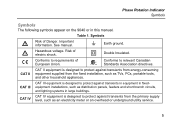
..., and lighting systems in large buildings. Risk of electric shock. CAT II CAT II equipment is designed to protect against transients in equipment in this manual. J Earth ground. Phase Rotation Indicator Symbols Symbols The following symbols appear on the 9040 or in fixedequipment installations, such as an electricity meter or an overhead or underground utility service...
..., and lighting systems in large buildings. Risk of electric shock. CAT II CAT II equipment is designed to protect against transients in equipment in this manual. J Earth ground. Phase Rotation Indicator Symbols Symbols The following symbols appear on the 9040 or in fixedequipment installations, such as an electricity meter or an overhead or underground utility service...
User Manual
Page 10
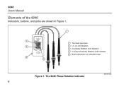
The 9040 Phase Rotation Indicator bbx02f.eps 6 Test lead input jack L1, L2, L3 Indicators Clockwise Rotation LCD Indicator Counter-Clockwise Rotation LCD Indicator Brief Instructions on instrument rear Figure 1. 9040 Users Manual Elements of the 9040 Indicators, buttons, and jacks are shown in Figure 1.
The 9040 Phase Rotation Indicator bbx02f.eps 6 Test lead input jack L1, L2, L3 Indicators Clockwise Rotation LCD Indicator Counter-Clockwise Rotation LCD Indicator Brief Instructions on instrument rear Figure 1. 9040 Users Manual Elements of the 9040 Indicators, buttons, and jacks are shown in Figure 1.
User Manual
Page 11
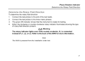
... powered from the installation under test. 7 Connect the test probes to the three mains phases. 3. Either the clockwise or counter-clockwise rotary indicator illuminates showing the type of L1, L2, or L3. Note The 9040 is ready for more information. XW Warning The rotary indicator lights even if the neutral conductor, N, is connected instead of rotary field direction...
... powered from the installation under test. 7 Connect the test probes to the three mains phases. 3. Either the clockwise or counter-clockwise rotary indicator illuminates showing the type of L1, L2, or L3. Note The 9040 is ready for more information. XW Warning The rotary indicator lights even if the neutral conductor, N, is connected instead of rotary field direction...
User Manual
Page 12
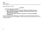
Abrasives or solvents will damage the 9040 case. 9040 Users Manual Maintaining the 9040 W Caution To prevent damage to the 9040: • Do not attempt to repair or service the 9040 unless qualified to do so. • Make sure that the relevant calibration, performance test, and service information is inspection and cleaning. Periodically wipe the case with soap and water and remove any residue afterwards. 8 Clean only with a damp cloth and mild detergent. The only maintenance the 9040 requires is being used. • Do not use abrasives or solvents.
Abrasives or solvents will damage the 9040 case. 9040 Users Manual Maintaining the 9040 W Caution To prevent damage to the 9040: • Do not attempt to repair or service the 9040 unless qualified to do so. • Make sure that the relevant calibration, performance test, and service information is inspection and cleaning. Periodically wipe the case with soap and water and remove any residue afterwards. 8 Clean only with a damp cloth and mild detergent. The only maintenance the 9040 requires is being used. • Do not use abrasives or solvents.
User Manual
Page 13
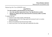
... Fuse (9040UK only) Replacing the Fuse (9040UK only) XW Warning For safe operation and maintenance of the finger guard and unscrew the tip in a counter- clockwise direction. 3. Insert a new fuse in front of the product: • Use only specified replacement fuses. Check the fuse using a simple continuity test. 2. Remove the defective fuse from the fuse holder. 4. See Specifications section. • Before you replace the fuse, disconnect the accessory (cable...
... Fuse (9040UK only) Replacing the Fuse (9040UK only) XW Warning For safe operation and maintenance of the finger guard and unscrew the tip in a counter- clockwise direction. 3. Insert a new fuse in front of the product: • Use only specified replacement fuses. Check the fuse using a simple continuity test. 2. Remove the defective fuse from the fuse holder. 4. See Specifications section. • Before you replace the fuse, disconnect the accessory (cable...
User Manual
Page 14
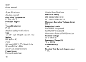
... mm (0.25 x 1.26 in) Electrical Specifications Power Supply From unit under test 10 Safety Specifications Electrical Safety IEC 61010-1/EN 61010 IEC 61557-7/EN 61557-7 Maximum Operating Voltage (Ume) 690 V Protection Levels CAT III/600 V to ground CAT IV/300 V to ground Determine Rotary Field Direction Nominal Voltage 40 to 690 V ac Frequency Range (fn) 15 to 400 Hz...
... mm (0.25 x 1.26 in) Electrical Specifications Power Supply From unit under test 10 Safety Specifications Electrical Safety IEC 61010-1/EN 61010 IEC 61557-7/EN 61557-7 Maximum Operating Voltage (Ume) 690 V Protection Levels CAT III/600 V to ground CAT IV/300 V to ground Determine Rotary Field Direction Nominal Voltage 40 to 690 V ac Frequency Range (fn) 15 to 400 Hz...


