User Manual
Page 1
9040 Phase Rotation Indicator Users Manual PN 2438546 April 2005, Rev.2, 5/11 © 2005-2011 Fluke Corporation. All product names are subject to change without notice. Specifications are trademarks of their respective companies. All rights reserved.
9040 Phase Rotation Indicator Users Manual PN 2438546 April 2005, Rev.2, 5/11 © 2005-2011 Fluke Corporation. All product names are subject to change without notice. Specifications are trademarks of their respective companies. All rights reserved.
User Manual
Page 5
.... To view, print, or download the latest manual supplement, visit http://us.fluke.com/usen/support/manuals. 1 9040 Introduction The Fluke 9040 Phase Rotation Indicator (the 9040) is a handheld instrument designed to detect the rotary field of three-phase systems. How to Contact Fluke To contact Fluke, call one of the following telephone numbers: • Technical Support USA: 1-800-44...
.... To view, print, or download the latest manual supplement, visit http://us.fluke.com/usen/support/manuals. 1 9040 Introduction The Fluke 9040 Phase Rotation Indicator (the 9040) is a handheld instrument designed to detect the rotary field of three-phase systems. How to Contact Fluke To contact Fluke, call one of the following telephone numbers: • Technical Support USA: 1-800-44...
User Manual
Page 7
Warning identifies conditions and actions that may damage the 9040. XW Warning To prevent possible electrical shock, fire, or personal injury: • Carefully read all instructions. • Comply with local and national ... protective equipment (approved rubber gloves, face protection, and flameresistant clothes) to the user. Examine the test leads for damaged insulation or exposed metal. Phase Rotation Indicator Safety Information Safety Information Caution identifies conditions and actions that pose hazard(s) to prevent shock and arc blast injury where hazardous live conductors are...
Warning identifies conditions and actions that may damage the 9040. XW Warning To prevent possible electrical shock, fire, or personal injury: • Carefully read all instructions. • Comply with local and national ... protective equipment (approved rubber gloves, face protection, and flameresistant clothes) to the user. Examine the test leads for damaged insulation or exposed metal. Phase Rotation Indicator Safety Information Safety Information Caution identifies conditions and actions that pose hazard(s) to prevent shock and arc blast injury where hazardous live conductors are...
User Manual
Page 9
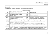
Important information. See manual. X Hazardous voltage. Table 1. T Double Insulated. Phase Rotation Indicator Symbols Symbols The following symbols appear on the 9040 or in large buildings. CAT II CAT II equipment is designed to protect against transients from the fixed installation, such as an electricity meter or ...
Important information. See manual. X Hazardous voltage. Table 1. T Double Insulated. Phase Rotation Indicator Symbols Symbols The following symbols appear on the 9040 or in large buildings. CAT II CAT II equipment is designed to protect against transients from the fixed installation, such as an electricity meter or ...
User Manual
Page 10
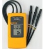
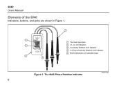
Test lead input jack L1, L2, L3 Indicators Clockwise Rotation LCD Indicator Counter-Clockwise Rotation LCD Indicator Brief Instructions on instrument rear Figure 1. 9040 Users Manual Elements of the 9040 Indicators, buttons, and jacks are shown in Figure 1. The 9040 Phase Rotation Indicator bbx02f.eps 6
Test lead input jack L1, L2, L3 Indicators Clockwise Rotation LCD Indicator Counter-Clockwise Rotation LCD Indicator Brief Instructions on instrument rear Figure 1. 9040 Users Manual Elements of the 9040 Indicators, buttons, and jacks are shown in Figure 1. The 9040 Phase Rotation Indicator bbx02f.eps 6
User Manual
Page 11
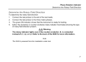
Phase Rotation Indicator Determine the Rotary Field Direction Determine the Rotary Field Direction To determine the rotary field direction: 1. Connect the test probes to the end of the 9040 for testing. 4. Note The 9040 is connected instead of rotary field direction present. The green ON indicator shows that the instrument is ready for more information...
Phase Rotation Indicator Determine the Rotary Field Direction Determine the Rotary Field Direction To determine the rotary field direction: 1. Connect the test probes to the end of the 9040 for testing. 4. Note The 9040 is connected instead of rotary field direction present. The green ON indicator shows that the instrument is ready for more information...
User Manual
Page 13
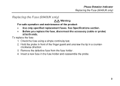
.... To replace the fuse: 1. Check the fuse using a simple continuity test. 2. Hold the probe in front of the product: • Use only specified replacement fuses. Phase Rotation Indicator Replacing the Fuse (9040UK only) Replacing the Fuse (9040UK only) XW Warning For safe operation and maintenance of the finger guard and unscrew the...
.... To replace the fuse: 1. Check the fuse using a simple continuity test. 2. Hold the probe in front of the product: • Use only specified replacement fuses. Phase Rotation Indicator Replacing the Fuse (9040UK only) Replacing the Fuse (9040UK only) XW Warning For safe operation and maintenance of the finger guard and unscrew the...

