Fluke 726 Process Calibrator Datasheet
Page 1
... auto ramp features • Power transmitters during test using any of 0.01%. • Transmitter error% calculation, interpret calibration results without the help of a switch • Custom RTD curves, add calibration constants for certified RTD probes for enhanced temperature measurement. • New voltage input protection design for compatibility with broad workload coverage, calibration power and unsurpassed accuracy in mind. Pressure Enabled For more detailed information visit www.fluke...
... auto ramp features • Power transmitters during test using any of 0.01%. • Transmitter error% calculation, interpret calibration results without the help of a switch • Custom RTD curves, add calibration constants for certified RTD probes for enhanced temperature measurement. • New voltage input protection design for compatibility with broad workload coverage, calibration power and unsurpassed accuracy in mind. Pressure Enabled For more detailed information visit www.fluke...
Fluke 726 Process Calibrator Datasheet
Page 2
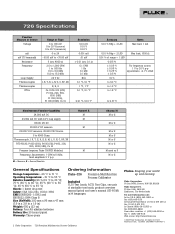
... 9090, Everett, WA USA 98206 Fluke Europe B.V. Printed in ) Weight: 650 g (23 oz) Battery: Four AA alkaline batteries Battery life: 25 hours typical Warranty: Three-years Ordering Information Fluke-726 Precision Multifunction Process Calibrator Included TL75 Test Leads, AC72 Test Clips, one pair of range + 1 LSD 0.015 % ± 0.05 % ± 0.05 % ± 0.25 % ± 0.5 % For frequency source; 1 V to 20 V p-p squarewave, -0.1 V offset...
... 9090, Everett, WA USA 98206 Fluke Europe B.V. Printed in ) Weight: 650 g (23 oz) Battery: Four AA alkaline batteries Battery life: 25 hours typical Warranty: Three-years Ordering Information Fluke-726 Precision Multifunction Process Calibrator Included TL75 Test Leads, AC72 Test Clips, one pair of range + 1 LSD 0.015 % ± 0.05 % ± 0.05 % ± 0.25 % ± 0.5 % For frequency source; 1 V to 20 V p-p squarewave, -0.1 V offset...
FE 726 Users Manual
Page 2
... not apply to fuses, disposable batteries, or to be free from defects in transit. Parts, product repairs, and services are warranted for damage in material and workmanship under normal use outside the product's specified rating, or normal wear and tear of mechanical components, Fluke will be returned to every buyer. Fluke warrants that software will be error free or operate without interruption. Following...
... not apply to fuses, disposable batteries, or to be free from defects in transit. Parts, product repairs, and services are warranted for damage in material and workmanship under normal use outside the product's specified rating, or normal wear and tear of mechanical components, Fluke will be returned to every buyer. Fluke warrants that software will be error free or operate without interruption. Following...
FE 726 Users Manual
Page 4
... Modules 28 Using Source Mode...30 Sourcing 4 to 20-mA Transmitter 30 Sourcing Other Electrical Parameters 32 Simulating Thermocouples 34 Simulating RTDs ...36 Sourcing Pressure...38 Setting 0 % and 100 % Output Parameters 41 % Error Functionality 41 Stepping and Ramping the Output 41 Manually Stepping the mA Output 42 Auto Ramping the Output 42 Storing and Recalling Setups 42 Store a Setup ...42 Recall a Setup ...43 ii...
... Modules 28 Using Source Mode...30 Sourcing 4 to 20-mA Transmitter 30 Sourcing Other Electrical Parameters 32 Simulating Thermocouples 34 Simulating RTDs ...36 Sourcing Pressure...38 Setting 0 % and 100 % Output Parameters 41 % Error Functionality 41 Stepping and Ramping the Output 41 Manually Stepping the mA Output 42 Auto Ramping the Output 42 Storing and Recalling Setups 42 Store a Setup ...42 Recall a Setup ...43 ii...
FE 726 Users Manual
Page 5
...) Storing and Recalling Data 43 Storing Data...43 Recall Data ...44 Pulse Train Source/Read 44 Calibrating a Transmitter 45 Calibrating a Pressure Transmitter 47 Calibrating an I/P Device 49 Pressure Switch Test...51 Testing an Output Device 51 Remote Control Commands 52 HART Functionality...52 Maintenance ...53 Replacing the Batteries 53 Cleaning the Calibrator 54 Service Center Calibration or Repair 54 Replacement Parts 54 Accessories ...56 External Fluke Pressure Module Compatibility 56 Specifications ...59 DC Voltage...
...) Storing and Recalling Data 43 Storing Data...43 Recall Data ...44 Pulse Train Source/Read 44 Calibrating a Transmitter 45 Calibrating a Pressure Transmitter 47 Calibrating an I/P Device 49 Pressure Switch Test...51 Testing an Output Device 51 Remote Control Commands 52 HART Functionality...52 Maintenance ...53 Replacing the Batteries 53 Cleaning the Calibrator 54 Service Center Calibration or Repair 54 Replacement Parts 54 Accessories ...56 External Fluke Pressure Module Compatibility 56 Specifications ...59 DC Voltage...
FE 726 Users Manual
Page 11
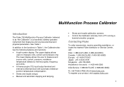
... and recalls calibration screens. • Control the Calibrator remotely from a PC running a terminal emulator program. To register your product, visit register.fluke.com 1 See Table 1. The lower display allows the user to measure volts, current, and pressure only. In addition to as "the Calibrator") is a handheld, battery-operated instrument that measures and sources electrical and physical parameters. Contacting Fluke To order accessories, receive operating assistance, or...
... and recalls calibration screens. • Control the Calibrator remotely from a PC running a terminal emulator program. To register your product, visit register.fluke.com 1 See Table 1. The lower display allows the user to measure volts, current, and pressure only. In addition to as "the Calibrator") is a handheld, battery-operated instrument that measures and sources electrical and physical parameters. Contacting Fluke To order accessories, receive operating assistance, or...
FE 726 Users Manual
Page 13
... test. 3 To order replacement parts, see Table 8. The items listed below and shown in Figure 1 are included with CAN/CSAC22.2 NO. 61010-1-04, UL 61010-1, and ISA 82.02.01 XW Warning To avoid possible electric shock or personal injury, use the Calibrator only as specified in Figure 1) • 725/726 CD-ROM (contains Users Manual; A Warning identifies...
... test. 3 To order replacement parts, see Table 8. The items listed below and shown in Figure 1 are included with CAN/CSAC22.2 NO. 61010-1-04, UL 61010-1, and ISA 82.02.01 XW Warning To avoid possible electric shock or personal injury, use the Calibrator only as specified in Figure 1) • 725/726 CD-ROM (contains Users Manual; A Warning identifies...
FE 726 Users Manual
Page 14
... range for the measurement. • Make sure the battery door is damaged. Protection may be impaired. Replace damaged test leads before opening the battery door. • Inspect the test leads for cracks or missing plastic. 726 Users Manual XW Warning To avoid possible electric shock or personal injury: • Use the Calibrator only as described in doubt, have the Calibrator serviced...
... range for the measurement. • Make sure the battery door is damaged. Protection may be impaired. Replace damaged test leads before opening the battery door. • Inspect the test leads for cracks or missing plastic. 726 Users Manual XW Warning To avoid possible electric shock or personal injury: • Use the Calibrator only as described in doubt, have the Calibrator serviced...
FE 726 Users Manual
Page 15
... process pressure line is shut off and depressurized before connecting it or disconnecting it from the pressure module. • Use only 4 AA batteries, properly installed in the Calibrator case, to power the Calibrator. • Disconnect test leads before changing to another measure or source function. • When servicing the Calibrator, use only specified replacement parts. • To avoid false readings, which could lead...
... process pressure line is shut off and depressurized before connecting it or disconnecting it from the pressure module. • Use only 4 AA batteries, properly installed in the Calibrator case, to power the Calibrator. • Disconnect test leads before changing to another measure or source function. • When servicing the Calibrator, use only specified replacement parts. • To avoid false readings, which could lead...
FE 726 Users Manual
Page 24
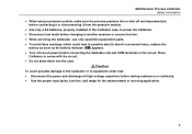
... TRIGGER/STOP RRReeRtteeuuccrrnnaalllttoo 25% 25% 0% Figure 5. Press C until Contst Adjust appears on /off • °C/°F • Frequency/Pulse output voltage • Pulse output frequency • HART resistor on the display. 2. 726 Users Manual Configuration Menus Use the configuration menus to set or change these parameters of the Calibrator: • Contrast Adjustment • Shut Down Mode • CJC on/off To enter the configuration menus...
... TRIGGER/STOP RRReeRtteeuuccrrnnaalllttoo 25% 25% 0% Figure 5. Press C until Contst Adjust appears on /off • °C/°F • Frequency/Pulse output voltage • Pulse output frequency • HART resistor on the display. 2. 726 Users Manual Configuration Menus Use the configuration menus to set or change these parameters of the Calibrator: • Contrast Adjustment • Shut Down Mode • CJC on/off To enter the configuration menus...
FE 726 Users Manual
Page 26
... Calibrator. Connect the Calibrator's voltage output to turn on the display. 2. M 3. Press V to select dc voltage (upper display). Press and hold G to enter 1 V as the 100 % value. 7. Press and hold J to enter 5 V as the 0 % value. 6. 726 Users Manual HART Resistor ON/OFF 1. The Calibrator is turned on both mA channels. 16 Getting Started This section details some basic operations of the Calibrator. Note When HART mode...
... Calibrator. Connect the Calibrator's voltage output to turn on the display. 2. M 3. Press V to select dc voltage (upper display). Press and hold G to enter 1 V as the 100 % value. 7. Press and hold J to enter 5 V as the 0 % value. 6. 726 Users Manual HART Resistor ON/OFF 1. The Calibrator is turned on both mA channels. 16 Getting Started This section details some basic operations of the Calibrator. Note When HART mode...
FE 726 Users Manual
Page 38
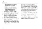
.... 2. Connect a pressure module to psi, mmHg, inHg, cmH2O@4 °C, cmH2O@20 °C, inH2O@4 °C, inH O@20 2 °C, inH O@60 2 °F, mbar, bar, kg/cm2, or kPa. 726 Users Manual • Never apply pressure above the rated maximum printed on the pressure modules accept standard ¼ NPT pipe fittings. Continue pressing A to change pressure display units to the Calibrator...
.... 2. Connect a pressure module to psi, mmHg, inHg, cmH2O@4 °C, cmH2O@20 °C, inH2O@4 °C, inH O@20 2 °C, inH O@60 2 °F, mbar, bar, kg/cm2, or kPa. 726 Users Manual • Never apply pressure above the rated maximum printed on the pressure modules accept standard ¼ NPT pipe fittings. Continue pressing A to change pressure display units to the Calibrator...
FE 726 Users Manual
Page 40
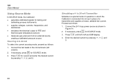
... pressing X,W,Y, and Z. 30 Press V until both mA and SIM display. 4. 726 Users Manual Using Source Mode In SOURCE mode, the Calibrator: • generates calibrated signals for testing and calibrating process instruments • supplies voltages, currents, frequencies, and resistances • simulates the electrical output of a transmitter and supplies a known, settable test current. If necessary, press for SOURCE mode. 3. M 2. Connect the test leads in Figure 14. to 20 mA To...
... pressing X,W,Y, and Z. 30 Press V until both mA and SIM display. 4. 726 Users Manual Using Source Mode In SOURCE mode, the Calibrator: • generates calibrated signals for testing and calibrating process instruments • supplies voltages, currents, frequencies, and resistances • simulates the electrical output of a transmitter and supplies a known, settable test current. If necessary, press for SOURCE mode. 3. M 2. Connect the test leads in Figure 14. to 20 mA To...

FE 726 Users Manual
Page 46
... under test as follows to provide the extra wires. The Calibrator simulates a 2-wire RTD at its front panel. See Figure 17. 3. Proceed as shown in Figure 17. Press Y and Z to select a different digit to the instrument under test exceeds the limits of the 726. 36 726 Users Manual Simulating RTDs Connect the Calibrator to edit. 4. Enter the desired temperature by...
... under test as follows to provide the extra wires. The Calibrator simulates a 2-wire RTD at its front panel. See Figure 17. 3. Proceed as shown in Figure 17. Press Y and Z to select a different digit to the instrument under test exceeds the limits of the 726. 36 726 Users Manual Simulating RTDs Connect the Calibrator to edit. 4. Enter the desired temperature by...
FE 726 Users Manual
Page 50
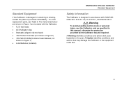
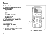
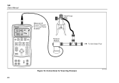
Connections for Sourcing Pressure bec47f.eps 40 726 Users Manual 726 PRECISION CALIBRATOR Measure mA Source Pressure 24 V Loop Power Enabled Hand Pump %Error V mA LOOP ZERO 3 Seconds OPEN/CLOSE SWITCH TEST MEAS SOURCE HART V mA TC RTD FREQ PULSE CONFIG SELECTION SAVE RECALL ENTER TRIGGER/STOP Return to Recall EXIT CONFIG 100% 25% 25% 00%% Pressure Module To Unit Under Test Figure 18.
Connections for Sourcing Pressure bec47f.eps 40 726 Users Manual 726 PRECISION CALIBRATOR Measure mA Source Pressure 24 V Loop Power Enabled Hand Pump %Error V mA LOOP ZERO 3 Seconds OPEN/CLOSE SWITCH TEST MEAS SOURCE HART V mA TC RTD FREQ PULSE CONFIG SELECTION SAVE RECALL ENTER TRIGGER/STOP Return to Recall EXIT CONFIG 100% 25% 25% 00%% Pressure Module To Unit Under Test Figure 18.
FE 726 Users Manual
Page 54
... input pulses or sources output pulses. The number of 5 for each memory location (1-8). 44 5. L works as a trigger/stop key in this mode since ramping or stepping during a pulse train is set the frequency and output voltage. Push S twice. Push W to return to the same RECALL DATA location to highlight RECL DATA (bottom right of the display changes to "Configuration Menus" earlier in this manual...
... input pulses or sources output pulses. The number of 5 for each memory location (1-8). 44 5. L works as a trigger/stop key in this mode since ramping or stepping during a pulse train is set the frequency and output voltage. Push S twice. Push W to return to the same RECALL DATA location to highlight RECL DATA (bottom right of the display changes to "Configuration Menus" earlier in this manual...
FE 726 Users Manual
Page 62
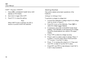
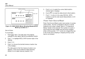
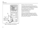
... remote control commands give access to facilitate use with HART communication devices. 726 Users Manual Remote Control Commands The Calibrator may be switched in or out using config selection menus. bec25f.eps Figure 23. Use a HART communicator when measuring mA with the exception of pressure measurement. See the Fluke Web Site for the 726 Remote Programming application note at www.fluke.com/processtools HART Functionality The Calibrator...
... remote control commands give access to facilitate use with HART communication devices. 726 Users Manual Remote Control Commands The Calibrator may be switched in or out using config selection menus. bec25f.eps Figure 23. Use a HART communicator when measuring mA with the exception of pressure measurement. See the Fluke Web Site for the 726 Remote Programming application note at www.fluke.com/processtools HART Functionality The Calibrator...
FE 726 Users Manual
Page 66
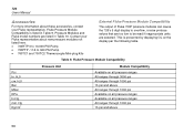
... ranges Available on the display per the following table. H20 Bar Mbar KPa In.Hg. 726 Users Manual Accessories For more information about new pressure modules not listed here. • 700HTP 0 to 10,000 PSI Pump • 700PTP -11.6 to 360 PSI Pump • 700TC1 and 700TC2 Thermocouple Mini-plug Kits External Fluke Pressure Module Compatibility The output of Fluke 700P pressure modules can cause the 726's 5 digit display...
... ranges Available on the display per the following table. H20 Bar Mbar KPa In.Hg. 726 Users Manual Accessories For more information about new pressure modules not listed here. • 700HTP 0 to 10,000 PSI Pump • 700PTP -11.6 to 360 PSI Pump • 700TC1 and 700TC2 Thermocouple Mini-plug Kits External Fluke Pressure Module Compatibility The output of Fluke 700P pressure modules can cause the 726's 5 digit display...

FE 726 Users Manual
Page 70
Frequency response is compatible with smart transmitters and PLCs. 726 Users Manual Ohms Measurement Ohms Range Ohms Read (low) Ohms Read (high) Ohms Source Ohms Range Minimum Ohms Source (low) 5.0 5.0 Ohms Source (high) 400 1500 Unit is ≤ 5 mS Frequency Measurement Range CPM Read Hz Read KHz Read Minimum 0.00 401.0 Maximum 400.0 400.0 1500 4000 Minimum 2.0 1.0 1.00 Maximum 400.00 4000...
Frequency response is compatible with smart transmitters and PLCs. 726 Users Manual Ohms Measurement Ohms Range Ohms Read (low) Ohms Read (high) Ohms Source Ohms Range Minimum Ohms Source (low) 5.0 5.0 Ohms Source (high) 400 1500 Unit is ≤ 5 mS Frequency Measurement Range CPM Read Hz Read KHz Read Minimum 0.00 401.0 Maximum 400.0 400.0 1500 4000 Minimum 2.0 1.0 1.00 Maximum 400.00 4000...
FE 726 Users Manual
Page 78
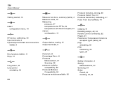
... Output terminals, 8 -P- Parts list, 54 Percentage Error, 41 Pressure Measurement, 27 Sourcing, 38 pressure modules compatibility, 56 Pressure Modules Compatibility, 56 Pressure modules available, 56 Pressure modules, zeroing, 28 Pressure Switch Test, 51 Pressure transmitter, calibrating, 47 Pulse Train Source/Read, 44 -R- I - Safety information, 3 Saving Measurements, 43 Servicing, 54 Setup Recall, 43 recalling, 42, 43 ramping, 41 Recalling setups, 42, 43 Remote control commands, 52 Repair...
... Output terminals, 8 -P- Parts list, 54 Percentage Error, 41 Pressure Measurement, 27 Sourcing, 38 pressure modules compatibility, 56 Pressure Modules Compatibility, 56 Pressure modules available, 56 Pressure modules, zeroing, 28 Pressure Switch Test, 51 Pressure transmitter, calibrating, 47 Pulse Train Source/Read, 44 -R- I - Safety information, 3 Saving Measurements, 43 Servicing, 54 Setup Recall, 43 recalling, 42, 43 ramping, 41 Recalling setups, 42, 43 Remote control commands, 52 Repair...


