Fluke 561 Infrared and Contact Thermometer Datasheet
Page 1
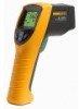
... • Very easy to use the Fluke 561's handy Velcro® pipe probe or, plug in any industrystandard, K-type mini-connector thermocouple probe you quickly identify problems • Scan large areas or small objects quickly and efficiently Laser-guided sighting for measuring pipes and other contact and ambient measurements • Single-point laser sighting • Temperature range of -40 °C to...
... • Very easy to use the Fluke 561's handy Velcro® pipe probe or, plug in any industrystandard, K-type mini-connector thermocouple probe you quickly identify problems • Scan large areas or small objects quickly and efficiently Laser-guided sighting for measuring pipes and other contact and ambient measurements • Single-point laser sighting • Temperature range of -40 °C to...
Fluke 561 Infrared and Contact Thermometer Datasheet
Page 2
... shutoff Laser power Relative humidity Power Battery life (alkaline) Display hold Backlit display Operating temperature Storage temperature MAX, MIN, DIF temperatures Thermocouple type K mini-adapter input Thermocouple type K Velcro® pipe probe Warranty Fluke 561 -40 °C to 550 °C (-40 °F to 14 µm Single-point laser Laser turns off above ambient temperature of reading 12:1 Adjustable with three settings: low (0.3), medium...
... shutoff Laser power Relative humidity Power Battery life (alkaline) Display hold Backlit display Operating temperature Storage temperature MAX, MIN, DIF temperatures Thermocouple type K mini-adapter input Thermocouple type K Velcro® pipe probe Warranty Fluke 561 -40 °C to 550 °C (-40 °F to 14 µm Single-point laser Laser turns off above ambient temperature of reading 12:1 Adjustable with three settings: low (0.3), medium...
FE 561 Users Manual
Page 1
® 561 Infrared Thermometer Users Manual PN 2562924 February 2006 Rev.2, 9/07 © 2006, 2007 Fluke Corporation, All rights reserved. All product names are trademarks of their respective companies. Printed in China.
® 561 Infrared Thermometer Users Manual PN 2562924 February 2006 Rev.2, 9/07 © 2006, 2007 Fluke Corporation, All rights reserved. All product names are trademarks of their respective companies. Printed in China.
FE 561 Users Manual
Page 2
...damages, this limitation of the problem. Box 1186 5602 BD Eindhoven The Netherlands To obtain service during the warranty period, contact your nearest Fluke authorized service center to obtain return authorization information, then send the product to that Service Center with a description of ... FROM ANY CAUSE OR THEORY. This warranty does not cover fuses, disposable batteries, or damage from the date of operation or handling. LIMITED WARRANTY AND LIMITATION OF LIABILITY This Fluke product will be free from defects in material and workmanship for two years from accident...
...damages, this limitation of the problem. Box 1186 5602 BD Eindhoven The Netherlands To obtain service during the warranty period, contact your nearest Fluke authorized service center to obtain return authorization information, then send the product to that Service Center with a description of ... FROM ANY CAUSE OR THEORY. This warranty does not cover fuses, disposable batteries, or damage from the date of operation or handling. LIMITED WARRANTY AND LIMITATION OF LIABILITY This Fluke product will be free from defects in material and workmanship for two years from accident...
FE 561 Users Manual
Page 3
Table of Contents Title Page Introduction ...1 Contacting Fluke...1 Safety Information 2 Features ...3 Display...4 Buttons and Connector 5 How the Thermometer Works 6 Operating the Thermometer 6 Locating a Hot or Cold Spot 6 Distance and Spot Size 6 Field of View...7 Emissivity...7 Switching Between °C and °F 8 Using the Contact Temperature Probe 9 HOLD ...10 Maintenance ...10 Changing the Battery 10 Cleaning the Lens 10 Cleaning the Housing 10 Troubleshooting...11 CE Certification...11 Specifications ...11 i
Table of Contents Title Page Introduction ...1 Contacting Fluke...1 Safety Information 2 Features ...3 Display...4 Buttons and Connector 5 How the Thermometer Works 6 Operating the Thermometer 6 Locating a Hot or Cold Spot 6 Distance and Spot Size 6 Field of View...7 Emissivity...7 Switching Between °C and °F 8 Using the Contact Temperature Probe 9 HOLD ...10 Maintenance ...10 Changing the Battery 10 Cleaning the Lens 10 Cleaning the Housing 10 Troubleshooting...11 CE Certification...11 Specifications ...11 i

FE 561 Users Manual
Page 4
561 Users Manual ii
561 Users Manual ii

FE 561 Users Manual
Page 6
561 Users Manual iv
561 Users Manual iv

FE 561 Users Manual
Page 7
Symbols and Safety Markings 3 2. Distance and Spot Size 7 6. Connecting the Temperature Probe 9 v Switching Between °C and °F 9 8. Locating a Hot or Cold Spot 6 5. Field of Figures Figure Title Page 1. Infrared Thermometer 4 3. Thermometer Display 5 4. List of View ...7 7.
Symbols and Safety Markings 3 2. Distance and Spot Size 7 6. Connecting the Temperature Probe 9 v Switching Between °C and °F 9 8. Locating a Hot or Cold Spot 6 5. Field of Figures Figure Title Page 1. Infrared Thermometer 4 3. Thermometer Display 5 4. List of View ...7 7.
FE 561 Users Manual
Page 9
... surface temperature by measuring the amount of the the Fluke 561. The Thermometer was designed specifically for use in the world: +1-425-446-5500 For USA Service: 1-888-99-FLUKE (1-888-993-5853) Or, visit Fluke's Web site at www.fluke.com. To register your product, visit register.fluke.com. 1 This manual covers all versions of infrared energy radiated by...
... surface temperature by measuring the amount of the the Fluke 561. The Thermometer was designed specifically for use in the world: +1-425-446-5500 For USA Service: 1-888-99-FLUKE (1-888-993-5853) Or, visit Fluke's Web site at www.fluke.com. To register your product, visit register.fluke.com. 1 This manual covers all versions of infrared energy radiated by...
FE 561 Users Manual
Page 10
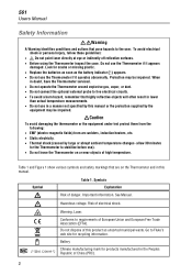
... Thermometer serviced. • Do not operate the Thermometer around explosive gas, vapor, or dust. • Do not connect the optional external probe to requirements of danger. Battery Chinese manufacturing mark for recycling information. When in a manner not specified by large or abrupt ambient temperature changes- Look for the Thermometer to the user. Risk of electrical shock. 561 Users Manual Safety Information XWWarning...
... Thermometer serviced. • Do not operate the Thermometer around explosive gas, vapor, or dust. • Do not connect the optional external probe to requirements of danger. Battery Chinese manufacturing mark for recycling information. When in a manner not specified by large or abrupt ambient temperature changes- Look for the Thermometer to the user. Risk of electrical shock. 561 Users Manual Safety Information XWWarning...
FE 561 Users Manual
Page 11
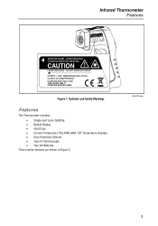
HLAISSAEPRERRATDUIRAETION LASER RADIATION - DO NOT STARE INTO BEAM OCC1C0LUOO4ATMM0SP.PP1SULL0T2IIEAE Infrared Thermometer Features CAUTION AISVOEMIDITETXEPDOFSRUORME T-
HLAISSAEPRERRATDUIRAETION LASER RADIATION - DO NOT STARE INTO BEAM OCC1C0LUOO4ATMM0SP.PP1SULL0T2IIEAE Infrared Thermometer Features CAUTION AISVOEMIDITETXEPDOFSRUORME T-
FE 561 Users Manual
Page 12
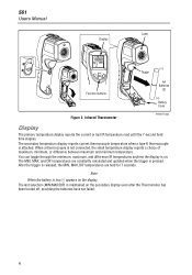
... are constantly calculated and updated when the trigger is pressed. 561 Users Manual Display Laser Trigger Function Buttons Figure 2. After the trigger is on. When a thermocouple is low, B appears on the secondary display even after the Thermometer has been turned off, providing the batteries have not failed. 4 Note When the battery is not connected, the small temperature display reports a choice of maximum...
... are constantly calculated and updated when the trigger is pressed. 561 Users Manual Display Laser Trigger Function Buttons Figure 2. After the trigger is on. When a thermocouple is low, B appears on the secondary display even after the Thermometer has been turned off, providing the batteries have not failed. 4 Note When the battery is not connected, the small temperature display reports a choice of maximum...
FE 561 Users Manual
Page 13
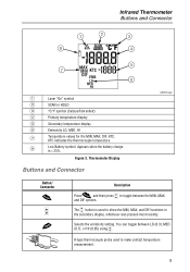
... (0.3), MED A (0.7), or HI (0.95) using . Thermometer Display Buttons and Connector efh01f.eps Button/ Connector C A D Description C A Press and then press to make contact temperature measurement. 5 You can toggle between the MIN, MAX, and DIF options. Figure 3. Selects the emissivity setting. KTC indicates the thermocouple temperature. A The button is < 25%. 1 8 Infrared Thermometer Buttons and Connector 2 3 4 5 7 6 A Laser "On" symbol B SCAN or HOLD C °C/°...
... (0.3), MED A (0.7), or HI (0.95) using . Thermometer Display Buttons and Connector efh01f.eps Button/ Connector C A D Description C A Press and then press to make contact temperature measurement. 5 You can toggle between the MIN, MAX, and DIF options. Figure 3. Selects the emissivity setting. KTC indicates the thermocouple temperature. A The button is < 25%. 1 8 Infrared Thermometer Buttons and Connector 2 3 4 5 7 6 A Laser "On" symbol B SCAN or HOLD C °C/°...
FE 561 Users Manual
Page 14
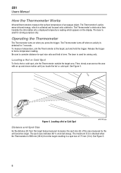
... area. Figure 4. 561 Users Manual How the Thermometer Works Infrared thermometers measure the surface temperature of view. Be sure to consider distance-to hold the trigger. Then, slowly scan across the area with an up and down motion until you press the trigger. The Thermometer's electronics then translate the information into a displayed temperature reading which is used for aiming...
... area. Figure 4. 561 Users Manual How the Thermometer Works Infrared thermometers measure the surface temperature of view. Be sure to consider distance-to hold the trigger. Then, slowly scan across the area with an up and down motion until you press the trigger. The Thermometer's electronics then translate the information into a displayed temperature reading which is used for aiming...
FE 561 Users Manual
Page 15
.... Distance and Spot Size efh005f.eps Field of your measurements with masking tape or flat black paint (< 148 °C/300 °F) and use tape, then you choose the best setting for typical situations. Experimentation, using the probe to determine benchmark temperatures, and experience will help you can be difficult to Table 2. Infrared Thermometer Operating the Thermometer 132...
.... Distance and Spot Size efh005f.eps Field of your measurements with masking tape or flat black paint (< 148 °C/300 °F) and use tape, then you choose the best setting for typical situations. Experimentation, using the probe to determine benchmark temperatures, and experience will help you can be difficult to Table 2. Infrared Thermometer Operating the Thermometer 132...
FE 561 Users Manual
Page 16
561 Users Manual Measured Surface Aluminum Oxidized Alloy A3003 Oxidized Roughened Brass Burnished Oxidized Copper Oxidized Electrical Terminal Blocks Haynes Alloy Inconel Oxidized Sandblasted Electoropolished Iron Oxidized Rusted Table 2. To toggle between the left side of the battery near the Thermometer wall. See Figure 7. 8 Surface Emissivity Switch Setting Low Low Low Low Low Medium Measured Surface Iron...
561 Users Manual Measured Surface Aluminum Oxidized Alloy A3003 Oxidized Roughened Brass Burnished Oxidized Copper Oxidized Electrical Terminal Blocks Haynes Alloy Inconel Oxidized Sandblasted Electoropolished Iron Oxidized Rusted Table 2. To toggle between the left side of the battery near the Thermometer wall. See Figure 7. 8 Surface Emissivity Switch Setting Low Low Low Low Low Medium Measured Surface Iron...
FE 561 Users Manual
Page 17
... show in the primary display. Infrared Thermometer Operating the Thermometer Switch Figure 7. Note With the probe inserted, the Thermometer stays on the top of the Thermometer. Switching Between °C and °F efh012f.eps Using the Contact Temperature Probe XWWarning To avoid electrical shock or personal injury, do not connect the optional external probe to live...
... show in the primary display. Infrared Thermometer Operating the Thermometer Switch Figure 7. Note With the probe inserted, the Thermometer stays on the top of the Thermometer. Switching Between °C and °F efh012f.eps Using the Contact Temperature Probe XWWarning To avoid electrical shock or personal injury, do not connect the optional external probe to live...
FE 561 Users Manual
Page 18
... tracking continuously changing temperature differentials on a damp sponge or soft cloth. The tapered probe is released. WCaution To avoid damaging the Thermometer, do NOT submerge it in Figure 2. 561 Users Manual Table 3 lists recommended Fluke temperature probes for quick, accurate refrigerant temperatures. HOLD appears in the last function selected. Cleaning the Lens Blow off loose particles using clean...
... tracking continuously changing temperature differentials on a damp sponge or soft cloth. The tapered probe is released. WCaution To avoid damaging the Thermometer, do NOT submerge it in Figure 2. 561 Users Manual Table 3 lists recommended Fluke temperature probes for quick, accurate refrigerant temperatures. HOLD appears in the last function selected. Cleaning the Lens Blow off loose particles using clean...
FE 561 Users Manual
Page 19
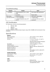
... (D:S 12:1 Emissivity Adjustment Three settings: low (0.3), medium (0.7), high (0.95) Contact Probe Input Input Temperature Range 40 °C to 550 °C (-40 °F to 1022 °F) Input Accuracy Input accuracy ± 1.1 °C (± 2 °F) Display Resolution 1 °C (1 °F) Laser Sighting Single point laser Power Class 2 (II) operation; Ambient temperature above 40 °C (104 °F) Action Select target within specifications Replace battery Check and/or replace battery 1.
... (D:S 12:1 Emissivity Adjustment Three settings: low (0.3), medium (0.7), high (0.95) Contact Probe Input Input Temperature Range 40 °C to 550 °C (-40 °F to 1022 °F) Input Accuracy Input accuracy ± 1.1 °C (± 2 °F) Display Resolution 1 °C (1 °F) Laser Sighting Single point laser Power Class 2 (II) operation; Ambient temperature above 40 °C (104 °F) Action Select target within specifications Replace battery Check and/or replace battery 1.
FE 561 Users Manual
Page 20
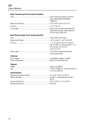
...;C (32 °F to 150 °F) Optional Accessories Soft Case 12 561 Users Manual Wrap Thermocouple Probe (model-specific) Type Type K with miniconnector and Velcro strap, ASTM E230-03 Standard Tolerance Measurement Range 0 °C to 100 °C (32 °F to 212 °F) Accuracy 2.2 °C (4.0 °F) Total Length 505 mm (20 in) cable terminated with a Type K thermocouple inside a 495 mm...
...;C (32 °F to 150 °F) Optional Accessories Soft Case 12 561 Users Manual Wrap Thermocouple Probe (model-specific) Type Type K with miniconnector and Velcro strap, ASTM E230-03 Standard Tolerance Measurement Range 0 °C to 100 °C (32 °F to 212 °F) Accuracy 2.2 °C (4.0 °F) Total Length 505 mm (20 in) cable terminated with a Type K thermocouple inside a 495 mm...


