Fluke 381 Clamp Meter Product Datasheet
Page 1
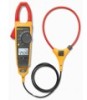
... to be carried up to 30 ft away from a clamp meter, and then lets you would expect from the point of measurement for added flexibility without interference with a detachable, remote display for easier, faster, safer measurements Technical Data The new Fluke 381 does everything you remove the display for use in noisy electrical...
... to be carried up to 30 ft away from a clamp meter, and then lets you would expect from the point of measurement for added flexibility without interference with a detachable, remote display for easier, faster, safer measurements Technical Data The new Fluke 381 does everything you remove the display for use in noisy electrical...
Fluke 381 Clamp Meter Product Datasheet
Page 2
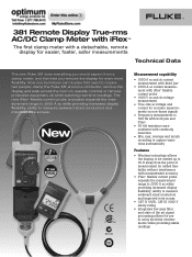
...to change switch positions while taking a measurement • Three-year warranty • Soft carrying case Ordering information 381 Remote Display True-rms Clamp Meter with iFlex™ Specifications Fluke 381 AC current via jaw AC current via iFlex™ DC current AC voltage DC voltage Resistance Frequency True-rms ... digits 2 % ± 5 digits 1.5 % ± 5 digits 1 % ± 5 digits 1 % ± 5 digits 0.5 % ± 5 digits Included Accessory 750 MCM or 2-500 MCM CAT III 1000V, CAT IV 600V 2 Fluke Corporation 381 Remote Display True-rms AC/DC Clamp Meter with iFlex™
...to change switch positions while taking a measurement • Three-year warranty • Soft carrying case Ordering information 381 Remote Display True-rms Clamp Meter with iFlex™ Specifications Fluke 381 AC current via jaw AC current via iFlex™ DC current AC voltage DC voltage Resistance Frequency True-rms ... digits 2 % ± 5 digits 1.5 % ± 5 digits 1 % ± 5 digits 1 % ± 5 digits 0.5 % ± 5 digits Included Accessory 750 MCM or 2-500 MCM CAT III 1000V, CAT IV 600V 2 Fluke Corporation 381 Remote Display True-rms AC/DC Clamp Meter with iFlex™
Fluke 381 Users Manual
Page 1
All rights reserved. Printed in China. Specifications are trademarks of their respective companies. All product names are subject to change without notice. 381 Remote Display True-rms Clamp Meter Users Manual PN 3538357 July 2010 © 2010 Fluke Corporation.
All rights reserved. Printed in China. Specifications are trademarks of their respective companies. All product names are subject to change without notice. 381 Remote Display True-rms Clamp Meter Users Manual PN 3538357 July 2010 © 2010 Fluke Corporation.
Fluke 381 Users Manual
Page 4
381 Users Manual Display...17 Measurements...19 AC and DC Current (Jaw 19 AC Current (Flexible Current Probe 22 AC and DC Voltage 23 Resistance/Continuity 26 Inrush Current Measurement (Jaw and Flexible Current Probe 26 Frequency Measurement (Jaw and Flexible Current Probe 28 Maintenance...28 Cleaning the Meter and Flexible Current Probe 28 Battery Replacement 29 User-Replaceable Parts 31 Specifications ...32 Electrical Specifications 32 Mechanical Specifications 37 Environmental Specifications 38 ii
381 Users Manual Display...17 Measurements...19 AC and DC Current (Jaw 19 AC Current (Flexible Current Probe 22 AC and DC Voltage 23 Resistance/Continuity 26 Inrush Current Measurement (Jaw and Flexible Current Probe 26 Frequency Measurement (Jaw and Flexible Current Probe 28 Maintenance...28 Cleaning the Meter and Flexible Current Probe 28 Battery Replacement 29 User-Replaceable Parts 31 Specifications ...32 Electrical Specifications 32 Mechanical Specifications 37 Environmental Specifications 38 ii
Fluke 381 Users Manual
Page 5
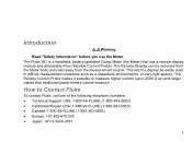
... in difficult-measurement situations such as a hazardous environments, or very tight spaces. The Remote Display can be easily read away from the measurement source. The Fluke 381 is a handheld, battery-operated Clamp Meter (the Meter) that traditional jawed meters cannot measure. The Flexible Current Probe makes it possible to measure higher current (up to Contact...
... in difficult-measurement situations such as a hazardous environments, or very tight spaces. The Remote Display can be easily read away from the measurement source. The Fluke 381 is a handheld, battery-operated Clamp Meter (the Meter) that traditional jawed meters cannot measure. The Flexible Current Probe makes it possible to measure higher current (up to Contact...
Fluke 381 Users Manual
Page 6
381 Users Manual • Singapore: +65-738-5655 • Anywhere in Table 1. To register your product, visit http://register.fluke.com. Symbols used on the Meter and in this manual or the protection provided by the Meter can be compromised. • Examine the case before the battery ... door is closed and latched before operating the Meter. • Remove the test leads from the Meter before you use the Meter. Carefully look at www.fluke.com. Safety Information A Warning identifies conditions and actions that could cause Meter damage, equipment under test damage, or permanent ...
381 Users Manual • Singapore: +65-738-5655 • Anywhere in Table 1. To register your product, visit http://register.fluke.com. Symbols used on the Meter and in this manual or the protection provided by the Meter can be compromised. • Examine the case before the battery ... door is closed and latched before operating the Meter. • Remove the test leads from the Meter before you use the Meter. Carefully look at www.fluke.com. Safety Information A Warning identifies conditions and actions that could cause Meter damage, equipment under test damage, or permanent ...
Fluke 381 Users Manual
Page 7
...; Be careful around explosive gas, vapor or in damp or wet environments. • Use only type AAA batteries, properly installed in the Meter case, to power the Meter. • To avoid false readings that can lead to electrical shock and injury, replace the batteries as soon as marked on the probes... leads before connecting the live test lead first. • Do not work alone so assistance can be rendered in doubt, have the Meter serviced. • Do not use the Meter around voltages > 30 V ac rms, 42 V ac peak, or 60 V dc. When disconnecting test leads, disconnect the live test lead....
...; Be careful around explosive gas, vapor or in damp or wet environments. • Use only type AAA batteries, properly installed in the Meter case, to power the Meter. • To avoid false readings that can lead to electrical shock and injury, replace the batteries as soon as marked on the probes... leads before connecting the live test lead first. • Do not work alone so assistance can be rendered in doubt, have the Meter serviced. • Do not use the Meter around voltages > 30 V ac rms, 42 V ac peak, or 60 V dc. When disconnecting test leads, disconnect the live test lead....
Fluke 381 Users Manual
Page 8
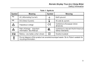
...installation under test: • Use the proper jacks, function, and range for the measurement application. 4 WCaution To avoid possible damage to the Meter or to prevent shock and arc blast injury where hazardous live conductors are exposed. • When measuring, keep fingers behind the Tactile Barrier. See... codes. Contact with the Flexible Current Probe. • Do not apply the Flexible Current Probe around bare conductors or bus bars. 381 Users Manual • Use extreme caution when working around or remove from HAZARDOUS LIVE conductors. • Take special care during fitting ...
...installation under test: • Use the proper jacks, function, and range for the measurement application. 4 WCaution To avoid possible damage to the Meter or to prevent shock and arc blast injury where hazardous live conductors are exposed. • When measuring, keep fingers behind the Tactile Barrier. See... codes. Contact with the Flexible Current Probe. • Do not apply the Flexible Current Probe around bare conductors or bus bars. 381 Users Manual • Use extreme caution when working around or remove from HAZARDOUS LIVE conductors. • Take special care during fitting ...
Fluke 381 Users Manual
Page 9
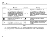
X Hazardous voltage P Conforms to relevant North American Safety Standards. See Manual. ) Conforms to European Union directives. Go to Fluke's website for recycling information. 5 B Battery. W Risk of this product as unsorted municipal waste. Remote Display True-rms Clamp Meter Safety Information Table 1. Symbols Symbol B F Meaning AC (Alternating Current) DC (Direct Current) Symbol J P Meaning Earth ground AC and dc current. Important information. T Double insulated ~ Do not dispose of Danger. Low battery when shown.
X Hazardous voltage P Conforms to relevant North American Safety Standards. See Manual. ) Conforms to European Union directives. Go to Fluke's website for recycling information. 5 B Battery. W Risk of this product as unsorted municipal waste. Remote Display True-rms Clamp Meter Safety Information Table 1. Symbols Symbol B F Meaning AC (Alternating Current) DC (Direct Current) Symbol J P Meaning Earth ground AC and dc current. Important information. T Double insulated ~ Do not dispose of Danger. Low battery when shown.
Fluke 381 Users Manual
Page 10
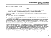
... component. 6 CAT IV IEC Measurement Category IV CAT IV equipment has protection against transients in equipment in large buildings. 381 Users Manual Symbol Meaning Symbol Meaning CAT III IEC Measurement Category III CAT III equipment has protection against transients from HAZARDOUS ...LIVE conductors is the LOWEST rating of test probe, test probe accessory, current clamp accessory, and the Meter is permitted. Conforms to or remove from HAZARDOUS LIVE conductors. , Application around and removal from the primary supply level, such ...
... component. 6 CAT IV IEC Measurement Category IV CAT IV equipment has protection against transients in equipment in large buildings. 381 Users Manual Symbol Meaning Symbol Meaning CAT III IEC Measurement Category III CAT III equipment has protection against transients from HAZARDOUS ...LIVE conductors is the LOWEST rating of test probe, test probe accessory, current clamp accessory, and the Meter is permitted. Conforms to or remove from HAZARDOUS LIVE conductors. , Application around and removal from the primary supply level, such ...
Fluke 381 Users Manual
Page 11
Examples of the FCC Rules. The Meter was tested and found to , personal computers, calculators, and equivalent electronic devices that can be determined by the general public. This equipment generates, uses, and ... equipment. These limits are marketed for operation by turning the equipment 7 Remote Display True-rms Clamp Meter Radio Frequency Data Radio Frequency Data Note Changes or modifications to the wireless 2.4 GHz radio not expressly approved by Fluke Corporation could void the user's authority to provide reasonable protection against harmful interference in a residential...
Examples of the FCC Rules. The Meter was tested and found to , personal computers, calculators, and equivalent electronic devices that can be determined by the general public. This equipment generates, uses, and ... equipment. These limits are marketed for operation by turning the equipment 7 Remote Display True-rms Clamp Meter Radio Frequency Data Radio Frequency Data Note Changes or modifications to the wireless 2.4 GHz radio not expressly approved by Fluke Corporation could void the user's authority to provide reasonable protection against harmful interference in a residential...
Fluke 381 Users Manual
Page 12
381 Users Manual off and on, the user is encouraged to try to correct the interference by one display module can be on . See Figure 2 and Table 2. Usually, the radio signal is off , remove the batteries from the Meter base and display module. It is docked on the Meter base ... or an experienced radio/TV technician for the radio signal to be synchronized with a Meter base when it is possible for help. The wireless radio signal does not hinder Meter measurements. Remote Display The Meter uses low-power 802.15.4 wireless technology to OFF. Different display modules can be ...
381 Users Manual off and on, the user is encouraged to try to correct the interference by one display module can be on . See Figure 2 and Table 2. Usually, the radio signal is off , remove the batteries from the Meter base and display module. It is docked on the Meter base ... or an experienced radio/TV technician for the radio signal to be synchronized with a Meter base when it is possible for help. The wireless radio signal does not hinder Meter measurements. Remote Display The Meter uses low-power 802.15.4 wireless technology to OFF. Different display modules can be ...

Fluke 381 Users Manual
Page 13
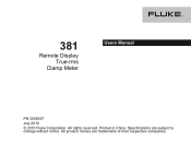
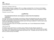
Remote Display ghn10.eps 9 To detach the display from each other before the radio signal connection is a radio connection when shows in the display. There is broken. This distance can be a maximum of 10 meters from the Meter base, see Figure 1. 1 2 Figure 1. Remote Display True-rms Clamp Meter Features The Meter base and display can change with the obstacles between the Meter base and display.
Remote Display ghn10.eps 9 To detach the display from each other before the radio signal connection is a radio connection when shows in the display. There is broken. This distance can be a maximum of 10 meters from the Meter base, see Figure 1. 1 2 Figure 1. Remote Display True-rms Clamp Meter Features The Meter base and display can change with the obstacles between the Meter base and display.
Fluke 381 Users Manual
Page 14
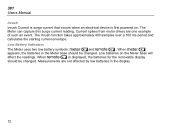
... voltage is used for 20 minutes. The high-performance AC Flexible Current Probe utilizes the Rogowski principle and is at the Meter input. 381 Users Manual Hazardous Voltage Indicator When the Meter senses a voltage ±30 V or a voltage overload (OL), Y is shown on the display and the red high-...voltage LED () on again. If the Meter powers off if there is disabled during Min Max Avg function use. To disable the...
... voltage is used for 20 minutes. The high-performance AC Flexible Current Probe utilizes the Rogowski principle and is at the Meter input. 381 Users Manual Hazardous Voltage Indicator When the Meter senses a voltage ±30 V or a voltage overload (OL), Y is shown on the display and the red high-...voltage LED () on again. If the Meter powers off if there is disabled during Min Max Avg function use. To disable the...

Fluke 381 Users Manual
Page 15
..., hold down while turning on and off after 2 minutes. DC Current Zero Push to display the average reading. Remote Display True-rms Clamp Meter Features Backlight Push to toggle the Backlight on the...
..., hold down while turning on and off after 2 minutes. DC Current Zero Push to display the average reading. Remote Display True-rms Clamp Meter Features Backlight Push to toggle the Backlight on the...
Fluke 381 Users Manual
Page 16
... a 100 ms period and calculates the starting current envelope. Low Battery Indicators The Meter uses two low battery symbols: Band Q. Low batteries on . Measurements are one example of such an event. 381 Users Manual Inrush Inrush Current is surge current that occurs when an electrical device is... displayed, the batteries for the removable display should be changed . Current spikes from motor drives are not affected by low batteries in the Meter base should be changed ....
... a 100 ms period and calculates the starting current envelope. Low Battery Indicators The Meter uses two low battery symbols: Band Q. Low batteries on . Measurements are one example of such an event. 381 Users Manual Inrush Inrush Current is surge current that occurs when an electrical device is... displayed, the batteries for the removable display should be changed . Current spikes from motor drives are not affected by low batteries in the Meter base should be changed ....
Fluke 381 Users Manual
Page 18
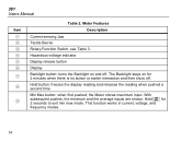
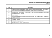
... maximum input. This function works in current, voltage, and frequency modes. 14 Meter Features Description Current sensing Jaw Tactile Barrier Rotary Function Switch, see Table 3. Hold button: freezes the display reading and releases the reading when pushed a second ... the Backlight on for 2 seconds to exit min max mode. Hold L for 2 minutes when there is no button or switch interaction and then shuts off . 381 Users Manual Item A B C D E F G H I Table 2.
... maximum input. This function works in current, voltage, and frequency modes. 14 Meter Features Description Current sensing Jaw Tactile Barrier Rotary Function Switch, see Table 3. Hold button: freezes the display reading and releases the reading when pushed a second ... the Backlight on for 2 seconds to exit min max mode. Hold L for 2 minutes when there is no button or switch interaction and then shuts off . 381 Users Manual Item A B C D E F G H I Table 2.
Fluke 381 Users Manual
Page 19
Remote Display True-rms Clamp Meter Features Item J K L M N O P Description Zero/Shift button: removes dc offset from dc current measurements. Integration time is 100 ms. Jaw release Alignment marks: to enter inrush mode. Inrush button: push to meet accuracy specifications, the conductor must be aligned with these marks. Push a second time to the yellow items on the Rotary Function Switch. Common terminal Volts/Ohm input terminal Flexible Current Probe input terminal 15 Also used to shift and corresponds to exit inrush mode.
Remote Display True-rms Clamp Meter Features Item J K L M N O P Description Zero/Shift button: removes dc offset from dc current measurements. Integration time is 100 ms. Jaw release Alignment marks: to enter inrush mode. Inrush button: push to meet accuracy specifications, the conductor must be aligned with these marks. Push a second time to the yellow items on the Rotary Function Switch. Common terminal Volts/Ohm input terminal Flexible Current Probe input terminal 15 Also used to shift and corresponds to exit inrush mode.
Fluke 381 Users Manual
Page 20
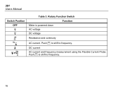
381 Users Manual Switch Position OFF K L K A C D Table 3. Rotary Function Switch Meter is powered down AC voltage DC voltage Function Resistance and continuity AC current. Push Z to shift to frequency. DC current AC current and frequency measurement using the Flexible Current Probe. Push Z to shift to frequency. 16
381 Users Manual Switch Position OFF K L K A C D Table 3. Rotary Function Switch Meter is powered down AC voltage DC voltage Function Resistance and continuity AC current. Push Z to shift to frequency. DC current AC current and frequency measurement using the Flexible Current Probe. Push Z to shift to frequency. 16
Fluke 381 Users Manual
Page 21
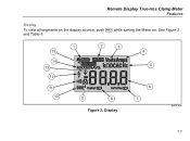
Remote Display True-rms Clamp Meter Features Display To view all segments on the display at once, push H while turning the Meter on. Display 4 5 6 7 ghn01.eps 17 See Figure 3 and Table 4. 15 14 13 12 11 10 1 2 3 9 8 Figure 3.
Remote Display True-rms Clamp Meter Features Display To view all segments on the display at once, push H while turning the Meter on. Display 4 5 6 7 ghn01.eps 17 See Figure 3 and Table 4. 15 14 13 12 11 10 1 2 3 9 8 Figure 3.


