Product Manual
Page 4
1586A Users Manual Digital I/O...1-22 Totalizer...1-22 Trigger ...1-22 Alarm Output 1-22 1586-2588 DAQ-STAQ Input Module Specifications 1-22 General ...1-22 1586-2586 High-Capacity Input Module Specifications 1-22 General ...1-22 2 Initial Setup and Configuration 2-1 Introduction...2-3 Set the Regional Voltage 2-3 Connect to Mains Power 2-4 Set the Handle Position 2-5 Power On and Standby 2-6 Warm-Up the Product 2-7 Configure the Product 2-7 Input Module and Relay Card Installation 2-8 Install a DAQ-STAQ Multiplexer Connection Module...
1586A Users Manual Digital I/O...1-22 Totalizer...1-22 Trigger ...1-22 Alarm Output 1-22 1586-2588 DAQ-STAQ Input Module Specifications 1-22 General ...1-22 1586-2586 High-Capacity Input Module Specifications 1-22 General ...1-22 2 Initial Setup and Configuration 2-1 Introduction...2-3 Set the Regional Voltage 2-3 Connect to Mains Power 2-4 Set the Handle Position 2-5 Power On and Standby 2-6 Warm-Up the Product 2-7 Configure the Product 2-7 Input Module and Relay Card Installation 2-8 Install a DAQ-STAQ Multiplexer Connection Module...
Product Manual
Page 5
... How to Read the Data CSV File 4-24 5 Measure/DMM Operation 5-1 Introduction...5-3 About the Measure Function 5-3 About the DMM Function 5-3 Input Type Selection and Range Adjustment 5-4 Relative Measurements 5-4 Graph the Measurements 5-5 Measurement Statistics 5-6 6 Maintenance and Care 6-1 Introduction...6-3 Clean the Product 6-3 Replace the Fuse 6-3 Memory Reset and Factory Reset 6-4 User-Replaceable Parts and Accessories 6-5 7 Error Messages and Troubleshooting 7-1 Introduction...7-3 iii MyFlukeStore Shop for Fluke products online at: www. .com...
... How to Read the Data CSV File 4-24 5 Measure/DMM Operation 5-1 Introduction...5-3 About the Measure Function 5-3 About the DMM Function 5-3 Input Type Selection and Range Adjustment 5-4 Relative Measurements 5-4 Graph the Measurements 5-5 Measurement Statistics 5-6 6 Maintenance and Care 6-1 Introduction...6-3 Clean the Product 6-3 Replace the Fuse 6-3 Memory Reset and Factory Reset 6-4 User-Replaceable Parts and Accessories 6-5 7 Error Messages and Troubleshooting 7-1 Introduction...7-3 iii MyFlukeStore Shop for Fluke products online at: www. .com...
Product Manual
Page 7
... Fuses...6-3 6-2. Fuses...2-3 2-2. PRT Channel Setup 3-23 3-9. The Scan Menu ...4-4 4-2. Scan Sample Rates 4-9 4-3. Scan Data Memory Usage 4-20 5-1. Resistance Channel Configuration 3-20 3-6. Math Channel Configuration 3-29 4-1. Types of Tables Table Title Page 1-1. Scan Statistics...4-13 4-4. Statistics ...5-6 6-1. Troublehooting Chart 7-20 v MyFlukeStore Shop for Fluke products online at: www. .com 1.888.610.7664 Channel Types and Numbers 3-10 3-3. Thermistor Channel Setup 3-22 3-8. User-Replaceable Parts and Accessories 6-5 7-1. List of Inputs...
... Fuses...6-3 6-2. Fuses...2-3 2-2. PRT Channel Setup 3-23 3-9. The Scan Menu ...4-4 4-2. Scan Sample Rates 4-9 4-3. Scan Data Memory Usage 4-20 5-1. Resistance Channel Configuration 3-20 3-6. Math Channel Configuration 3-29 4-1. Types of Tables Table Title Page 1-1. Scan Statistics...4-13 4-4. Statistics ...5-6 6-1. Troublehooting Chart 7-20 v MyFlukeStore Shop for Fluke products online at: www. .com 1.888.610.7664 Channel Types and Numbers 3-10 3-3. Thermistor Channel Setup 3-22 3-8. User-Replaceable Parts and Accessories 6-5 7-1. List of Inputs...
Product Manual
Page 8
....7664 List of a Scan Sweep 4-6 4-3. Fuse Replacement and Line-Voltage Selection 2-3 2-2. Main Power Switch and Standby Key 2-6 2-5. Scan Data File Name Convention 4-21 4-9. Rear-Panel Alarm Outputs 3-32 3-11. Screen Capture ...1-11 2-1. DAQ-STAQ Multiplexer Installation 2-12 3-1. 2-Wire, 3-Wire, and 4-Wire Input Module Connections 3-3 3-2. 2-Wire, 3-Wire, and 4-Wire Multiplexer Connections 3-4 3-3. 3-Wire and 4-Wire Channel Reservation 3-7 3-4. Totalizer Input (TOT 3-25 3-10. Scan Data ...4-13 4-5. External Temperature Control Source 4-16 4-8. Setup.csv...
....7664 List of a Scan Sweep 4-6 4-3. Fuse Replacement and Line-Voltage Selection 2-3 2-2. Main Power Switch and Standby Key 2-6 2-5. Scan Data File Name Convention 4-21 4-9. Rear-Panel Alarm Outputs 3-32 3-11. Screen Capture ...1-11 2-1. DAQ-STAQ Multiplexer Installation 2-12 3-1. 2-Wire, 3-Wire, and 4-Wire Input Module Connections 3-3 3-2. 2-Wire, 3-Wire, and 4-Wire Multiplexer Connections 3-4 3-3. 3-Wire and 4-Wire Channel Reservation 3-7 3-4. Totalizer Input (TOT 3-25 3-10. Scan Data ...4-13 4-5. External Temperature Control Source 4-16 4-8. Setup.csv...
Product Manual
Page 11
...; digits on the types and ranges of triggers such a timer, an alarm, an external source, or a remote SCPI command. The DMM can be viewed on the display. 1 Product Overview and Specifications Introduction Introduction This chapter supplies information about the Product, the manual set, safety information, contact information, and specifications. Sequentially scan up to graph and see Table 1-1). With the Graph feature, channel measurement data for up to view live data or...
...; digits on the types and ranges of triggers such a timer, an alarm, an external source, or a remote SCPI command. The DMM can be viewed on the display. 1 Product Overview and Specifications Introduction Introduction This chapter supplies information about the Product, the manual set, safety information, contact information, and specifications. Sequentially scan up to graph and see Table 1-1). With the Graph feature, channel measurement data for up to view live data or...
Product Manual
Page 12
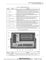
... the scan data record on the rear of external devices. • Digital I/O (DIO) - The alarms can sense and output. Counter increment is equipped with a unidirectional, resettable totalizer with a digital 8-bit transistor-transistor logic (TTL) port that can be assigned two independent alarms to output a digital signal from application software over a rear-panel USB or LAN TCP/IP connection. • Automated Sensor Test - Automatically sets the temperature of a Fluke Calibration...
... the scan data record on the rear of external devices. • Digital I/O (DIO) - The alarms can sense and output. Counter increment is equipped with a unidirectional, resettable totalizer with a digital 8-bit transistor-transistor logic (TTL) port that can be assigned two independent alarms to output a digital signal from application software over a rear-panel USB or LAN TCP/IP connection. • Automated Sensor Test - Automatically sets the temperature of a Fluke Calibration...
Product Manual
Page 14
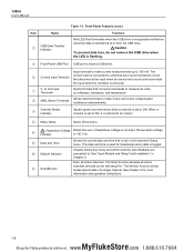
... 2. 1586A Users Manual Item Name USB Data Transfer Indicator Table 1-1. The Current Input Terminal current input is connected to a thermal over-current protection circuit that is set to as "active". Menu Name Name of the menu. Hazardous Voltage Warns the user of a single channel. This date and time is used for Fluke products online at: www. .com 1.888.610.7664 The Scan function...
... 2. 1586A Users Manual Item Name USB Data Transfer Indicator Table 1-1. The Current Input Terminal current input is connected to a thermal over-current protection circuit that is set to as "active". Menu Name Name of the menu. Hazardous Voltage Warns the user of a single channel. This date and time is used for Fluke products online at: www. .com 1.888.610.7664 The Scan function...
Product Manual
Page 15
... Fluke products online at: www. .com 1.888.610.7664 Channel Setup is powered on the top of the display. See Chapter 3 for more information and operation instructions. Push and hold the LOCK key to lock the front panel to prevent changes and UNLOCK to automatically start and stop with the front-panel DMM can be recorded. See "Set the Regional Voltage" in Chapter 2. 1 Product Overview and Specifications...
... Fluke products online at: www. .com 1.888.610.7664 Channel Setup is powered on the top of the display. See Chapter 3 for more information and operation instructions. Push and hold the LOCK key to lock the front panel to prevent changes and UNLOCK to automatically start and stop with the front-panel DMM can be recorded. See "Set the Regional Voltage" in Chapter 2. 1 Product Overview and Specifications...
Product Manual
Page 16
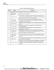
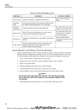
... Power Switch Mains Power Connector Chassis Ground Temperature Source Control Serial USB Port LAN Connection Totalizer Input DIO (Digital I/O Input Ports) Function Supplies and disconnects mains power to trigger a digital external alarm if a channel exceeds the set alarm limits. Mains power cord receptacle. Network port used for remote operation. See "Input Module and Relay Card Input Module Slots Installation" and "Install a DAQ-STAQ Multiplexer Connection Module" in Chapter 4. 1586A Users Manual Table...
... Power Switch Mains Power Connector Chassis Ground Temperature Source Control Serial USB Port LAN Connection Totalizer Input DIO (Digital I/O Input Ports) Function Supplies and disconnects mains power to trigger a digital external alarm if a channel exceeds the set alarm limits. Mains power cord receptacle. Network port used for remote operation. See "Input Module and Relay Card Input Module Slots Installation" and "Install a DAQ-STAQ Multiplexer Connection Module" in Chapter 4. 1586A Users Manual Table...
Product Manual
Page 17
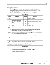
... read all instructions. 1-9 MyFlukeStore Shop for Fluke products online at the source of the building's low-voltage MAINS installation. Product Category: With reference to the equipment types in domestic household waste. Go to the user. Symbols Symbol Description Symbol Description Risk of this manual and on the Product. See Table 1-3 for a list of symbols used in...
... read all instructions. 1-9 MyFlukeStore Shop for Fluke products online at the source of the building's low-voltage MAINS installation. Product Category: With reference to the equipment types in domestic household waste. Go to the user. Symbols Symbol Description Symbol Description Risk of this manual and on the Product. See Table 1-3 for a list of symbols used in...

Product Manual
Page 20
... Product and replace the fuse in the manual set includes: • This 1586A Users Manual that contains feature information, operation instructions, and basic user maintenance and troubleshooting information. The Product Manual Set The Product manual set . 1-12 MyFlukeStore Shop for first time use. • Chapter 3 supplies instructions on how to wire inputs to the Input Module then configure the associated channel. • Chapter 4 supplies information and instructions on how to do a scan, monitor a channel, and record measurement data. • Chapter 5 supplies instructions on how...
... Product and replace the fuse in the manual set includes: • This 1586A Users Manual that contains feature information, operation instructions, and basic user maintenance and troubleshooting information. The Product Manual Set The Product manual set . 1-12 MyFlukeStore Shop for first time use. • Chapter 3 supplies instructions on how to wire inputs to the Input Module then configure the associated channel. • Chapter 4 supplies information and instructions on how to do a scan, monitor a channel, and record measurement data. • Chapter 5 supplies instructions on how...
Product Manual
Page 37
... into the slot. 1586A Users Manual Menu Item Table 2-2. Remote Port Configure the LAN Ethernet or serial USB communication settings. See "Automatic Power Loss Scan Resume" in Chapter 4 for more information. See the 1586A Calibration Manual for more information. The card should easily move when the rails of the relay card into the slot guides. 6. See "Set Up Security" in the slot guides. 7. Input Module and Relay Card Installation Before an Input Module can be...
... into the slot. 1586A Users Manual Menu Item Table 2-2. Remote Port Configure the LAN Ethernet or serial USB communication settings. See "Automatic Power Loss Scan Resume" in Chapter 4 for more information. See the 1586A Calibration Manual for more information. The card should easily move when the rails of the relay card into the slot guides. 6. See "Set Up Security" in the slot guides. 7. Input Module and Relay Card Installation Before an Input Module can be...
Product Manual
Page 44
... Introduction...3-3 Input Wiring...3-3 The 1586-2586 High Capacity Input Module 3-3 The 1586-2588 DAQ-STAQ Multiplexer Connector Module 3-4 Wiring Safety and Considerations 3-5 3-Wire and 4-Wire Sense Input Configuration 3-6 Input Types and Wiring Diagrams 3-7 Input Wiring Instructions 3-8 Channel Configuration 3-10 About Channel Numbers 3-10 Basic Channel Operations 3-12 Open the Channel Setup Menu 3-12 Set Channels to ON or OFF 3-13 Verify a Channel 3-14 Zero a Channel 3-14 Copy a Channel 3-15 Save or Load a Channel Configuration (Setup File 3-16 Reset the Channel and...
... Introduction...3-3 Input Wiring...3-3 The 1586-2586 High Capacity Input Module 3-3 The 1586-2588 DAQ-STAQ Multiplexer Connector Module 3-4 Wiring Safety and Considerations 3-5 3-Wire and 4-Wire Sense Input Configuration 3-6 Input Types and Wiring Diagrams 3-7 Input Wiring Instructions 3-8 Channel Configuration 3-10 About Channel Numbers 3-10 Basic Channel Operations 3-12 Open the Channel Setup Menu 3-12 Set Channels to ON or OFF 3-13 Verify a Channel 3-14 Zero a Channel 3-14 Copy a Channel 3-15 Save or Load a Channel Configuration (Setup File 3-16 Reset the Channel and...
Product Manual
Page 55
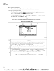
.... 1586A Users Manual Basic Channel Operations Use the instructions in the channel list. 3-12 MyFlukeStore Shop for Fluke products online at: www. .com 1.888.610.7664 Note The Channel Setup menu cannot be configured and the channel status indicator to perform basic channel operations. Channel status. Open the Channel Setup Menu The Channel Setup menu lets the user manage channels, verify inputs, and also set up and down the list of available channels. When ON, the channel can be accessed while a scan...
.... 1586A Users Manual Basic Channel Operations Use the instructions in the channel list. 3-12 MyFlukeStore Shop for Fluke products online at: www. .com 1.888.610.7664 Note The Channel Setup menu cannot be configured and the channel status indicator to perform basic channel operations. Channel status. Open the Channel Setup Menu The Channel Setup menu lets the user manage channels, verify inputs, and also set up and down the list of available channels. When ON, the channel can be accessed while a scan...
Product Manual
Page 61
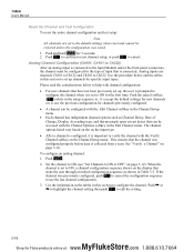
... the Edit Channel menu. Analog inputs are set to the default settings when reset and cannot be configured with the Edit Channel softkey in the Channel Setup menu. • Each channel has independent channel options such as shown in this section to set up , the user is prompted to configure the channel when it is important to help with channel configuration: • For new channels that is collected from a scan. To...
... the Edit Channel menu. Analog inputs are set to the default settings when reset and cannot be configured with the Edit Channel softkey in the Channel Setup menu. • Each channel has independent channel options such as shown in this section to set up , the user is prompted to configure the channel when it is important to help with channel configuration: • For new channels that is collected from a scan. To...
Product Manual
Page 69
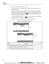
... Scan/Monitor menu. See "Read Mode" on the display that steps the user through an initial configuration sequence as follows (see Table 3-9): 1. Set the channel to ON or OFF. If the channel was previously configured, push to cancel the configuration sequence to the TOT terminal of the plug then insert the plug into the rear- Connect the wire to use the last channel...
... Scan/Monitor menu. See "Read Mode" on the display that steps the user through an initial configuration sequence as follows (see Table 3-9): 1. Set the channel to ON or OFF. If the channel was previously configured, push to cancel the configuration sequence to the TOT terminal of the plug then insert the plug into the rear- Connect the wire to use the last channel...
Product Manual
Page 83
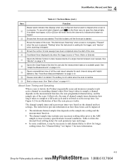
... for Fluke products online at: www. .com 1.888.610.7664 The channel sample times and scan sweep times vary based on the sample rate setting and the measurement function. • The channel sample time includes any configured channel alarm is tripped while a scan is tripped. Shows then the scan was started . The Scan Menu (cont.) Item Function Master alarm indicator that lets the user plot the measurement data...
... for Fluke products online at: www. .com 1.888.610.7664 The channel sample times and scan sweep times vary based on the sample rate setting and the measurement function. • The channel sample time includes any configured channel alarm is tripped while a scan is tripped. Shows then the scan was started . The Scan Menu (cont.) Item Function Master alarm indicator that lets the user plot the measurement data...
Product Manual
Page 91
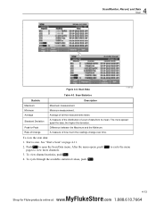
... much the readings change over time. Rate of Change A measure of all the measurements taken. Push to view more spread apart the data, the higher the deviation. After the menu opens, push to cycle the menu pages to open the Scan Data menu. To view channel statistics, push . 4. Scan Statistics Statistic Description Maximum Maximum measurement. The more channels. 3. See "Start a Scan" on page...
... much the readings change over time. Rate of Change A measure of all the measurements taken. Push to view more spread apart the data, the higher the deviation. After the menu opens, push to cycle the menu pages to open the Scan Data menu. To view channel statistics, push . 4. Scan Statistics Statistic Description Maximum Maximum measurement. The more channels. 3. See "Start a Scan" on page...

Product Manual
Page 134
.... 1586A Users Manual Troubleshooting In the event that supplies power to the Product is plugged in the slot. Several possible problem conditions are illuminated but the display is blank. If a problem occurs, please read this section carefully and attempt to tell the Service Technician. Replace the fuse once. DO NOT replace the fuse with one of a component part. If the fuse blows a second time, it is not properly set...
.... 1586A Users Manual Troubleshooting In the event that supplies power to the Product is plugged in the slot. Several possible problem conditions are illuminated but the display is blank. If a problem occurs, please read this section carefully and attempt to tell the Service Technician. Replace the fuse once. DO NOT replace the fuse with one of a component part. If the fuse blows a second time, it is not properly set...
Product Manual
Page 135
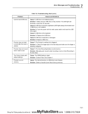
... sure the USB drive is not installed.) Solution 2: Cycle the power with default settings. Cause 2: USB driver locked by application (LED lights always illuminated even if USB drive is fully inserted. Solution: Contact Fluke. Cause: The internal memory or USB drive is started. Product does not start to start a scan. The LED light will illuminate in the test setup. Cause 4: USB drive inoperative or damaged. Table 7-2. Cause 1: The Auto Recording feature...
... sure the USB drive is not installed.) Solution 2: Cycle the power with default settings. Cause 2: USB driver locked by application (LED lights always illuminated even if USB drive is fully inserted. Solution: Contact Fluke. Cause: The internal memory or USB drive is started. Product does not start to start a scan. The LED light will illuminate in the test setup. Cause 4: USB drive inoperative or damaged. Table 7-2. Cause 1: The Auto Recording feature...


