Service Manual
Page 1
Printed in the Netherlands All product names are trademarks of their respective companies. All rights reserved. 123/124 Industrial ScopeMeter Service Manual 4822 872 05389 February 2003 © 2003 Fluke Corporation.
Printed in the Netherlands All product names are trademarks of their respective companies. All rights reserved. 123/124 Industrial ScopeMeter Service Manual 4822 872 05389 February 2003 © 2003 Fluke Corporation.

Service Manual
Page 2
and Canada +31-402-675-200 in U.S.A. SERVICE CENTERS To locate an authorized service center, visit us on the World Wide Web: http://www.fluke.com or call Fluke using any of the phone numbers listed below: +1-888-993-5853 in Europe +1-425-446-5500 from other countries
and Canada +31-402-675-200 in U.S.A. SERVICE CENTERS To locate an authorized service center, visit us on the World Wide Web: http://www.fluke.com or call Fluke using any of the phone numbers listed below: +1-888-993-5853 in Europe +1-425-446-5500 from other countries

Service Manual
Page 3
... Dual Input Oscilloscope 2-3 2.2.1 Vertical 2-3 2.2.2 Horizontal 2-4 2.2.3 Trigger 2-4 2.2.4 Advanced Scope Functions 2-5 2.3 Dual Input Meter 2-5 2.3.1 Input A and Input B 2-5 2.3.2 Input A 2-8 2.3.3 Advanced Meter Functions 2-9 2.4 Cursor Readout (Fluke 124 2-9 2.5 Miscellaneous 2-9 2.6 Environmental 2-11 2.7 Service and Maintenance 2-12 2.8 Safety ...2-12 2.9 EMC Immunity 2-14 Circuit Descriptions 3-1 3.1 Introduction 3-3 3.2 Block Diagram 3-3 3.2.1 Channel A, Channel B Measurement Circuits 3-4 3.2.2 Trigger Circuit 3-4 3.2.3 Digital Circuit 3-5 3.2.4 Power Circuit 3-6
... Dual Input Oscilloscope 2-3 2.2.1 Vertical 2-3 2.2.2 Horizontal 2-4 2.2.3 Trigger 2-4 2.2.4 Advanced Scope Functions 2-5 2.3 Dual Input Meter 2-5 2.3.1 Input A and Input B 2-5 2.3.2 Input A 2-8 2.3.3 Advanced Meter Functions 2-9 2.4 Cursor Readout (Fluke 124 2-9 2.5 Miscellaneous 2-9 2.6 Environmental 2-11 2.7 Service and Maintenance 2-12 2.8 Safety ...2-12 2.9 EMC Immunity 2-14 Circuit Descriptions 3-1 3.1 Introduction 3-3 3.2 Block Diagram 3-3 3.2.1 Channel A, Channel B Measurement Circuits 3-4 3.2.2 Trigger Circuit 3-4 3.2.3 Digital Circuit 3-5 3.2.4 Power Circuit 3-6

Service Manual
Page 4
... 5.6.7 Gain Ohm 5-13 5.6.8 Capacitance Gain Low and High 5-14 5.6.9 Capacitance Clamp & Zero 5-14 5.6.10 Capacitance Gain 5-15 5.7 Save Calibration Data and Exit 5-15 123/124 Service Manual 3.2.5 Start-up Sequence, Operating Modes 3-7 3.3 Detailed Circuit Descriptions 3-9 3.3.1 Power Circuit 3-9 3.3.2 Channel A -
... 5.6.7 Gain Ohm 5-13 5.6.8 Capacitance Gain Low and High 5-14 5.6.9 Capacitance Clamp & Zero 5-14 5.6.10 Capacitance Gain 5-15 5.7 Save Calibration Data and Exit 5-15 123/124 Service Manual 3.2.5 Start-up Sequence, Operating Modes 3-7 3.3 Detailed Circuit Descriptions 3-9 3.3.1 Power Circuit 3-9 3.3.2 Channel A -

Service Manual
Page 10
123/124 Service Manual 5-6. Volt Gain Calibration Input Connections
123/124 Service Manual 5-6. Volt Gain Calibration Input Connections

Service Manual
Page 13
... and to prevent personal injury. 1.4 Symbols used in addition to be done only by qualified service personnel. Warning Calls attention to a potential danger that both operating and service personnel follow generally accepted safety procedures in this Manual and on the instrument. 1.3 Caution and ...the correct and safe use the instrument. To avoid electrical shock, do not service the instrument unless you are marked on Instrument Read the safety information in a safe condition. Warning Servicing described in this manual is to the safety precautions specified in this instrument it ...
... and to prevent personal injury. 1.4 Symbols used in addition to be done only by qualified service personnel. Warning Calls attention to a potential danger that both operating and service personnel follow generally accepted safety procedures in this Manual and on the instrument. 1.3 Caution and ...the correct and safe use the instrument. To avoid electrical shock, do not service the instrument unless you are marked on Instrument Read the safety information in a safe condition. Warning Servicing described in this manual is to the safety precautions specified in this instrument it ...

Service Manual
Page 14
123/124 Service Manual 1.5 Impaired Safety Whenever it is opened. Components which are indicated with an asterisk (*) in the List of the instrument may only be replaced by ... sources. Capacitors inside the instrument can be dangerous to life. The matter should then be referred to be gained by components obtained through your local FLUKE organization.
123/124 Service Manual 1.5 Impaired Safety Whenever it is opened. Components which are indicated with an asterisk (*) in the List of the instrument may only be replaced by ... sources. Capacitors inside the instrument can be dangerous to life. The matter should then be referred to be gained by components obtained through your local FLUKE organization.

Service Manual
Page 15
Chapter 2 Characteristics Title Page 2.1 Introduction 2-3 2.2 Dual Input Oscilloscope 2-3 2.2.1 Vertical 2-3 2.2.2 Horizontal 2-4 2.2.3 Trigger 2-4 2.2.4 Advanced Scope Functions 2-5 2.3 Dual Input Meter 2-5 2.3.1 Input A and Input B 2-5 2.3.2 Input A 2-8 2.3.3 Advanced Meter Functions 2-9 2.4 Cursor Readout (Fluke 124 2-9 2.5 Miscellaneous 2-9 2.6 Environmental 2-11 2.7 Service and Maintenance 2-12 2.8 Safety ...2-12 2.9 EMC Immunity 2-14 2-1
Chapter 2 Characteristics Title Page 2.1 Introduction 2-3 2.2 Dual Input Oscilloscope 2-3 2.2.1 Vertical 2-3 2.2.2 Horizontal 2-4 2.2.3 Trigger 2-4 2.2.4 Advanced Scope Functions 2-5 2.3 Dual Input Meter 2-5 2.3.1 Input A and Input B 2-5 2.3.2 Input A 2-8 2.3.3 Advanced Meter Functions 2-9 2.4 Cursor Readout (Fluke 124 2-9 2.5 Miscellaneous 2-9 2.6 Environmental 2-11 2.7 Service and Maintenance 2-12 2.8 Safety ...2-12 2.9 EMC Immunity 2-14 2-1

Service Manual
Page 18
... changing time base or sensitivity Normal & Single mode ±0.04 divisions (= ±1 pixel) 2.2.2 Horizontal Scope Modes Normal, Single, Roll Ranges Normal: equivalent sampling (Fluke 123) equivalent sampling (Fluke 124) real time sampling 20 ns to 500 ns/div 10 ns to 500 ns/div 1 µs to 5 s/div Single (real time) 1 µs to.... Input Voltage A and B Direct, with test leads, or with VP40 Probe 600 Vrms with BB120 300 Vrms (For detailed specifications see "2.8 Safety") Max. 123/124 Service Manual Display Modes A, -A, B, -B Max.
... changing time base or sensitivity Normal & Single mode ±0.04 divisions (= ±1 pixel) 2.2.2 Horizontal Scope Modes Normal, Single, Roll Ranges Normal: equivalent sampling (Fluke 123) equivalent sampling (Fluke 124) real time sampling 20 ns to 500 ns/div 10 ns to 500 ns/div 1 µs to 5 s/div Single (real time) 1 µs to.... Input Voltage A and B Direct, with test leads, or with VP40 Probe 600 Vrms with BB120 300 Vrms (For detailed specifications see "2.8 Safety") Max. 123/124 Service Manual Display Modes A, -A, B, -B Max.

Service Manual
Page 20
... Scale Reading 500 counts Frequency (Hz) Ranges 1Hz, 10Hz, 100Hz, 1 kHz, 10 kHz, 100 kHz, 1 MHz, 10 MHz, and 50 MHz (Fluke 123) or 70 MHz (Fluke 124). 123/124 Service Manual Full Scale Reading 5000 counts Move influence ±6 counts max. Frequency Range for 5 to 100% of range DC coupled: DC to...
... Scale Reading 500 counts Frequency (Hz) Ranges 1Hz, 10Hz, 100Hz, 1 kHz, 10 kHz, 100 kHz, 1 MHz, 10 MHz, and 50 MHz (Fluke 123) or 70 MHz (Fluke 124). 123/124 Service Manual Full Scale Reading 5000 counts Move influence ±6 counts max. Frequency Range for 5 to 100% of range DC coupled: DC to...

Service Manual
Page 22
123/124 Service Manual Full Scale Reading Phase Modes Range Accuracy Resolution 2.3.2 Input A Ohm (Ω) Ranges Accuracy Full Scale Reading 500Ω to 5 MΩ 30 MΩ Measurement Current ...
123/124 Service Manual Full Scale Reading Phase Modes Range Accuracy Resolution 2.3.2 Input A Ohm (Ω) Ranges Accuracy Full Scale Reading 500Ω to 5 MΩ 30 MΩ Measurement Current ...
Service Manual
Page 24
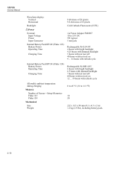
123/124 Service Manual Waveform display: Vertical Horizontal Backlight Power External: Input Voltage Power Input Connector Internal Battery Pack BP120 (Fluke 123): Battery Power Operating Time Charging Time 8 divisions of 20 pixels 9.6 divisions of 25 pixels Cold Cathode Fluorescent (CCFL) via ... tool off 60 hours with test tool on 12 ... 19 hours with refresh cycle Allowable ambient temperature during charging Memory Number of Screen + Setup Memories Fluke 123 Fluke 124 Mechanical Size Weight 0 to 45 °C (32 to 113 °F) 10 20 232 x 115 x 50 mm (9.1 x 4.5 x 2 in) 1.2 kg (2.5 lbs),...
123/124 Service Manual Waveform display: Vertical Horizontal Backlight Power External: Input Voltage Power Input Connector Internal Battery Pack BP120 (Fluke 123): Battery Power Operating Time Charging Time 8 divisions of 20 pixels 9.6 divisions of 25 pixels Cold Cathode Fluorescent (CCFL) via ... tool off 60 hours with test tool on 12 ... 19 hours with refresh cycle Allowable ambient temperature during charging Memory Number of Screen + Setup Memories Fluke 123 Fluke 124 Mechanical Size Weight 0 to 45 °C (32 to 113 °F) 10 20 232 x 115 x 50 mm (9.1 x 4.5 x 2 in) 1.2 kg (2.5 lbs),...

Service Manual
Page 26
... 2-1/2. 300V rms. For derating see Figure 2-1. 600 Vrms up to -BNC Adapter BB120 Max. Maximum Input Voltage vs Frequency ST8112.CGM 123/124 Service Manual Enclosure Protection IP51, ref: IEC529 2.7 Service and Maintenance Calibration Interval 1 Year 2.8 Safety Designed for measurements on input, with leads, with VP40 With Banana-to 400Hz 2-12 Figure 2-1.
... 2-1/2. 300V rms. For derating see Figure 2-1. 600 Vrms up to -BNC Adapter BB120 Max. Maximum Input Voltage vs Frequency ST8112.CGM 123/124 Service Manual Enclosure Protection IP51, ref: IEC529 2.7 Service and Maintenance Calibration Interval 1 Year 2.8 Safety Designed for measurements on input, with leads, with VP40 With Banana-to 400Hz 2-12 Figure 2-1.

Service Manual
Page 28
... V/div 100 mV/div to 500 V/div E= 10 V/m 500 mV/div to 500 V/div 100 mV/div to 200 mV/div - 123/124 Service Manual 2.9 EMC Immunity The Fluke 123/124, including standard accessories, conforms with the EEC directive 89/336 for EMC immunity, as defined by IEC1000-4-3, with the addition of...
... V/div 100 mV/div to 500 V/div E= 10 V/m 500 mV/div to 500 V/div 100 mV/div to 200 mV/div - 123/124 Service Manual 2.9 EMC Immunity The Fluke 123/124, including standard accessories, conforms with the EEC directive 89/336 for EMC immunity, as defined by IEC1000-4-3, with the addition of...

Service Manual
Page 32
.... source, - Volts, and derived measurements (e.g. This signal is measured as for voltage measurements. For TV triggering the selected trigger source signal is possible. 123/124 Service Manual 3.2.1 Channel A, Channel B Measurement Circuits The Channel A and Channel B circuit are similar.
.... source, - Volts, and derived measurements (e.g. This signal is measured as for voltage measurements. For TV triggering the selected trigger source signal is possible. 123/124 Service Manual 3.2.1 Channel A, Channel B Measurement Circuits The Channel A and Channel B circuit are similar.

Service Manual
Page 34
123/124 Service Manual drivers, and a fluorescent back light lamp. The ON-OFF key is not included in the D-ASIC, that is active even when the test tool ...
123/124 Service Manual drivers, and a fluorescent back light lamp. The ON-OFF key is not included in the D-ASIC, that is active even when the test tool ...

Service Manual
Page 36
... OPTIONS, F1, activate refresh) if the test tool is on , directly following situations the batteries will be connected!), and then it is connected. 123/124 Service Manual Battery Refresh In the following the start up Sequence, Operating Modes Table 3-2 shows an overview of the test tool operating modes. 3-8 This prevents battery..., and the power adapter must be prompted for this action when he turns the test tool on , and the power adapter is completely charged again. Fluke 123/124 Start-up screen.
... OPTIONS, F1, activate refresh) if the test tool is on , directly following situations the batteries will be connected!), and then it is connected. 123/124 Service Manual Battery Refresh In the following the start up Sequence, Operating Modes Table 3-2 shows an overview of the test tool operating modes. 3-8 This prevents battery..., and the power adapter must be prompted for this action when he turns the test tool on , and the power adapter is completely charged again. Fluke 123/124 Start-up screen.

Service Manual
Page 38
... loaded, the mask software will keep running, and the test tool is not operative: the test tool is in the Operational & Charge mode. 123/124 Service Manual 3-10 As described in the D-ASIC, indicating the test tool ON/OFF status is toggled. By pressing the ON/OFF key, a bit in Section...
... loaded, the mask software will keep running, and the test tool is not operative: the test tool is in the Operational & Charge mode. 123/124 Service Manual 3-10 As described in the D-ASIC, indicating the test tool ON/OFF status is toggled. By pressing the ON/OFF key, a bit in Section...

Service Manual
Page 40
... turned on , the D-ASIC makes the PWRONOFF line (P-ASIC pin 62) high. Primary current Secondary current FLYGATE SIGNAL V554 "ON" V554 "OFF" Figure 3-5. 123/124 Service Manual loading C503 and C555 just after connecting the power adapter) via its Vgs (gate-source voltage) must be negative. Then a decreasing current flows in...
... turned on , the D-ASIC makes the PWRONOFF line (P-ASIC pin 62) high. Primary current Secondary current FLYGATE SIGNAL V554 "ON" V554 "OFF" Figure 3-5. 123/124 Service Manual loading C503 and C555 just after connecting the power adapter) via its Vgs (gate-source voltage) must be negative. Then a decreasing current flows in...

Service Manual
Page 42
... voltage is connected (or both). By changing the duty cycle of this signal, the output on -resistance of V604 can be turned off . 123/124 Service Manual 3-14 on pin 3 of the comparator step wise, by the D-ASIC provides a pulse width modulated (variable duty cycle) square wave. The comparator output SLOWADC...
... voltage is connected (or both). By changing the duty cycle of this signal, the output on -resistance of V604 can be turned off . 123/124 Service Manual 3-14 on pin 3 of the comparator step wise, by the D-ASIC provides a pulse width modulated (variable duty cycle) square wave. The comparator output SLOWADC...
