Service Manual
Page 1
123/124 Industrial ScopeMeter Service Manual 4822 872 05389 February 2003 © 2003 Fluke Corporation. All rights reserved. Printed in the Netherlands All product names are trademarks of their respective companies.
123/124 Industrial ScopeMeter Service Manual 4822 872 05389 February 2003 © 2003 Fluke Corporation. All rights reserved. Printed in the Netherlands All product names are trademarks of their respective companies.

Service Manual
Page 4
123/124 Service Manual 3.2.5 Start-up Sequence, Operating Modes 3-7 3.3 Detailed Circuit Descriptions 3-9 3.3.1 Power Circuit 3-9 3.3.2 Channel A - Channel B Measurement Circuits 3-15 3.3.3 Trigger Circuit 3-20 3.3.4 Digital Circuit and ADC's 3-25 Performance Verification 4-1 4.1 ...
123/124 Service Manual 3.2.5 Start-up Sequence, Operating Modes 3-7 3.3 Detailed Circuit Descriptions 3-9 3.3.1 Power Circuit 3-9 3.3.2 Channel A - Channel B Measurement Circuits 3-15 3.3.3 Trigger Circuit 3-20 3.3.4 Digital Circuit and ADC's 3-25 Performance Verification 4-1 4.1 ...

Service Manual
Page 10
Volt Gain Calibration Input Connections 123/124 Service Manual 5-6.
Volt Gain Calibration Input Connections 123/124 Service Manual 5-6.

Service Manual
Page 14
... your local FLUKE organization. Components which are indicated with an asterisk (*) in the List of the instrument may only be replaced by hand, is likely to expose live parts and accessible terminals which access can hold their charge even if the instrument has been separated from line power. 123/124 Service Manual 1.5 Impaired...
... your local FLUKE organization. Components which are indicated with an asterisk (*) in the List of the instrument may only be replaced by hand, is likely to expose live parts and accessible terminals which access can hold their charge even if the instrument has been separated from line power. 123/124 Service Manual 1.5 Impaired...

Service Manual
Page 18
... Normal & Single mode ±0.04 divisions (= ±1 pixel) 2.2.2 Horizontal Scope Modes Normal, Single, Roll Ranges Normal: equivalent sampling (Fluke 123) equivalent sampling (Fluke 124) real time sampling 20 ns to 500 ns/div 10 ns to 500 ns/div 1 µs to 5 s/div Single (real... 60 s/div Sampling Rate (for both channels simultaneously) Equivalent sampling (repetitive signals) up to 60 s/div Glitch detection is always active. 123/124 Service Manual Display Modes A, -A, B, -B Max. Input Voltage A and B Direct, with test leads, or with VP40 Probe 600 Vrms with BB120 300...
... Normal & Single mode ±0.04 divisions (= ±1 pixel) 2.2.2 Horizontal Scope Modes Normal, Single, Roll Ranges Normal: equivalent sampling (Fluke 123) equivalent sampling (Fluke 124) real time sampling 20 ns to 500 ns/div 10 ns to 500 ns/div 1 µs to 5 s/div Single (real... 60 s/div Sampling Rate (for both channels simultaneously) Equivalent sampling (repetitive signals) up to 60 s/div Glitch detection is always active. 123/124 Service Manual Display Modes A, -A, B, -B Max. Input Voltage A and B Direct, with test leads, or with VP40 Probe 600 Vrms with BB120 300...

Service Manual
Page 20
... Scale Reading 500 counts Frequency (Hz) Ranges 1Hz, 10Hz, 100Hz, 1 kHz, 10 kHz, 100 kHz, 1 MHz, 10 MHz, and 50 MHz (Fluke 123) or 70 MHz (Fluke 124). 123/124 Service Manual Full Scale Reading 5000 counts Move influence ±6 counts max. True RMS Voltages (VAC and VAC+DC) Ranges 500 mV, 5V, 50V...
... Scale Reading 500 counts Frequency (Hz) Ranges 1Hz, 10Hz, 100Hz, 1 kHz, 10 kHz, 100 kHz, 1 MHz, 10 MHz, and 50 MHz (Fluke 123) or 70 MHz (Fluke 124). 123/124 Service Manual Full Scale Reading 5000 counts Move influence ±6 counts max. True RMS Voltages (VAC and VAC+DC) Ranges 500 mV, 5V, 50V...

Service Manual
Page 22
123/124 Service Manual Full Scale Reading Phase Modes Range Accuracy Resolution 2.3.2 Input A Ohm (Ω) Ranges Accuracy Full Scale Reading 500Ω to 5 MΩ 30 MΩ Measurement Current Open ...
123/124 Service Manual Full Scale Reading Phase Modes Range Accuracy Resolution 2.3.2 Input A Ohm (Ω) Ranges Accuracy Full Scale Reading 500Ω to 5 MΩ 30 MΩ Measurement Current Open ...
Service Manual
Page 24
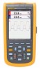
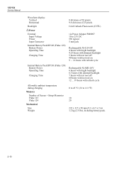
123/124 Service Manual Waveform display: Vertical Horizontal Backlight Power External: Input Voltage Power Input Connector Internal Battery Pack BP120 (Fluke 123): Battery Power Operating Time Charging Time 8 divisions of 20 pixels 9.6 divisions of 25 pixels Cold Cathode Fluorescent (CCFL) via ... tool off 60 hours with test tool on 12 ... 19 hours with refresh cycle Allowable ambient temperature during charging Memory Number of Screen + Setup Memories Fluke 123 Fluke 124 Mechanical Size Weight 0 to 45 °C (32 to 113 °F) 10 20 232 x 115 x 50 mm (9.1 x 4.5 x 2 in) 1.2 kg (2.5 lbs),...
123/124 Service Manual Waveform display: Vertical Horizontal Backlight Power External: Input Voltage Power Input Connector Internal Battery Pack BP120 (Fluke 123): Battery Power Operating Time Charging Time 8 divisions of 20 pixels 9.6 divisions of 25 pixels Cold Cathode Fluorescent (CCFL) via ... tool off 60 hours with test tool on 12 ... 19 hours with refresh cycle Allowable ambient temperature during charging Memory Number of Screen + Setup Memories Fluke 123 Fluke 124 Mechanical Size Weight 0 to 45 °C (32 to 113 °F) 10 20 232 x 115 x 50 mm (9.1 x 4.5 x 2 in) 1.2 kg (2.5 lbs),...

Service Manual
Page 26
... to ground 600 Vrms. For derating see Figure 2-1/2. 300V rms. For derating see Figure 2-1. 600 Vrms up to -BNC Adapter BB120 Max. 123/124 Service Manual Enclosure Protection IP51, ref: IEC529 2.7 Service and Maintenance Calibration Interval 1 Year 2.8 Safety Designed for measurements on input, with leads, with VP40 With Banana-to 400Hz 2-12 Figure 2-1.
... to ground 600 Vrms. For derating see Figure 2-1/2. 300V rms. For derating see Figure 2-1. 600 Vrms up to -BNC Adapter BB120 Max. 123/124 Service Manual Enclosure Protection IP51, ref: IEC529 2.7 Service and Maintenance Calibration Interval 1 Year 2.8 Safety Designed for measurements on input, with leads, with VP40 With Banana-to 400Hz 2-12 Figure 2-1.

Service Manual
Page 28
... VAC+DC with STL 120 and short ground lead • OHM, CONT, DIODE, and CAP with STL120 See Table 2-1 and Table 2-2. 123/124 Service Manual 2.9 EMC Immunity The Fluke 123/124, including standard accessories, conforms with the EEC directive 89/336 for EMC immunity, as defined by IEC1000-4-3, with the addition of full...
... VAC+DC with STL 120 and short ground lead • OHM, CONT, DIODE, and CAP with STL120 See Table 2-1 and Table 2-2. 123/124 Service Manual 2.9 EMC Immunity The Fluke 123/124, including standard accessories, conforms with the EEC directive 89/336 for EMC immunity, as defined by IEC1000-4-3, with the addition of full...

Service Manual
Page 32
123/124 Service Manual 3.2.1 Channel A, Channel B Measurement Circuits The Channel A and Channel B circuit are provided by the D-ASIC via the C-ASIC trigger output TRIG-A. Resistance, continuity, and diode measurements (...
123/124 Service Manual 3.2.1 Channel A, Channel B Measurement Circuits The Channel A and Channel B circuit are provided by the D-ASIC via the C-ASIC trigger output TRIG-A. Resistance, continuity, and diode measurements (...

Service Manual
Page 34
... mode power supply). So when the test tool is turned off , the battery supplies the +3V3GAR voltage via the RS232 optically isolated interface. 123/124 Service Manual drivers, and a fluorescent back light lamp. The D-ASIC drives the rows and scans the matrix. If the power adapter is possible via transistor V569. supply...
... mode power supply). So when the test tool is turned off , the battery supplies the +3V3GAR voltage via the RS232 optically isolated interface. 123/124 Service Manual drivers, and a fluorescent back light lamp. The D-ASIC drives the rows and scans the matrix. If the power adapter is possible via transistor V569. supply...

Service Manual
Page 36
... the memory effect. • after the battery has been removed, as the test tool does not know the battery status then. Fluke 123/124 Start-up screen. 123/124 Service Manual Battery Refresh In the following the start up Sequence, Operating Modes Table 3-2 shows an overview of the test tool operating modes. 3-8 The...
... the memory effect. • after the battery has been removed, as the test tool does not know the battery status then. Fluke 123/124 Start-up screen. 123/124 Service Manual Battery Refresh In the following the start up Sequence, Operating Modes Table 3-2 shows an overview of the test tool operating modes. 3-8 The...

Service Manual
Page 38
... then makes the CHAGATE signal high. The power adapter voltage is turned on pin 9 of energy loaded into L501/C503. This signal on . 123/124 Service Manual 3-10 As described in Section 3.2.5, the test tool operating mode depends on pin 20 (supplied via R502, and attenuated in the P-ASIC). If it is...
... then makes the CHAGATE signal high. The power adapter voltage is turned on pin 9 of energy loaded into L501/C503. This signal on . 123/124 Service Manual 3-10 As described in Section 3.2.5, the test tool operating mode depends on pin 20 (supplied via R502, and attenuated in the P-ASIC). If it is...

Service Manual
Page 40
..., the FlashROM, and the RAM is transferred to the secondary winding. CHAGATE control signal To make the FET conductive its internal Control circuit. 123/124 Service Manual loading C503 and C555 just after connecting the power adapter) via its Vgs (gate-source voltage) must be switched off will be negative with respect...
..., the FlashROM, and the RAM is transferred to the secondary winding. CHAGATE control signal To make the FET conductive its internal Control circuit. 123/124 Service Manual loading C503 and C555 just after connecting the power adapter) via its Vgs (gate-source voltage) must be switched off will be negative with respect...

Service Manual
Page 42
... the Power Adapter is present, serial communication is always possible, even when the test tool is received by V605 and V603. supply voltage. 123/124 Service Manual 3-14 on the RXD line. After half a cycle, a zero voltage is monitored by R600/R604, and fed back to switch. The PWM buck regulator consists...
... the Power Adapter is present, serial communication is always possible, even when the test tool is received by V605 and V603. supply voltage. 123/124 Service Manual 3-14 on the RXD line. After half a cycle, a zero voltage is monitored by R600/R604, and fed back to switch. The PWM buck regulator consists...

Service Manual
Page 44
.../R120, R112, R113, and-R114. The MIDADC signal (pin 28), supplied by a factor 10, the C-ASIC can be set to an input buffer. 123/124 Service Manual LF input The LF-input (pin 42) is 100 mV/div. Depending on the required range, the C-ASIC selects and buffers one of the input...
.../R120, R112, R113, and-R114. The MIDADC signal (pin 28), supplied by a factor 10, the C-ASIC can be set to an input buffer. 123/124 Service Manual LF input The LF-input (pin 42) is 100 mV/div. Depending on the required range, the C-ASIC selects and buffers one of the input...

Service Manual
Page 46
... shields and the black COM input, the PTC resistor will limit the resulting current. The reading range is charged with a constant known current. 123/124 Service Manual 3-18 range trace ../div range trace ../div Table 3-3. The voltage across Rx to the C-ASIC GPROT input, and causes a ground error warning (high voltage level...
... shields and the black COM input, the PTC resistor will limit the resulting current. The reading range is charged with a constant known current. 123/124 Service Manual 3-18 range trace ../div range trace ../div Table 3-3. The voltage across Rx to the C-ASIC GPROT input, and causes a ground error warning (high voltage level...

Service Manual
Page 48
... trace, also the frequency, pulse width, and duty cycle of reference voltages. • AC/DC relay and Resistance/Capacitance (Ω/F) relay control. 3-20 123/124 Service Manual Table 3-5. From the ADC samples to the D-ASIC. • Current source for resistance and capacitance measurements. • Voltage reference source: buffering and generation of the...
... trace, also the frequency, pulse width, and duty cycle of reference voltages. • AC/DC relay and Resistance/Capacitance (Ω/F) relay control. 3-20 123/124 Service Manual Table 3-5. From the ADC samples to the D-ASIC. • Current source for resistance and capacitance measurements. • Voltage reference source: buffering and generation of the...
Service Manual
Page 50
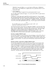
... the trigger moment, and the moment of the TRIGDT signal is the real trigger moment. This 80% gap is smaller than the gap. 123/124 Service Manual TRIGQUAL from a single period of the wave form, if the noise is 40 ns (sample rate 25 MHz).
... the trigger moment, and the moment of the TRIGDT signal is the real trigger moment. This 80% gap is smaller than the gap. 123/124 Service Manual TRIGQUAL from a single period of the wave form, if the noise is 40 ns (sample rate 25 MHz).


