Fluke 116 Users Manual
Page 2
.... Box 9090 Everett, WA 98206-9090 U.S.A. LIMITED WARRANTY AND LIMITATION OF LIABILITY This Fluke product will be free from defects in material and workmanship for three years from accident, neglect, misuse, alteration, contamination, or abnormal conditions of operation or handling. This warranty does not cover fuses, disposable batteries, or damage from the date of purchase...
.... Box 9090 Everett, WA 98206-9090 U.S.A. LIMITED WARRANTY AND LIMITATION OF LIABILITY This Fluke product will be free from defects in material and workmanship for three years from accident, neglect, misuse, alteration, contamination, or abnormal conditions of operation or handling. This warranty does not cover fuses, disposable batteries, or damage from the date of purchase...
Fluke 116 Users Manual
Page 3
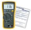
... Introduction The Fluke Model 116, is unspecified. 1 When making frequency measurements >1 kHz, the Y symbol is a battery-powered, true-rms multimeter (hereafter "the Meter") with a 6000-count display and a bar graph. Contacting Fluke To contact Fluke, call: USA: 1-888-99-FLUKE (1-888-993-5853) Canada: 1-800-36-FLUKE (1-800-363... in fixed-equipment installations at www.fluke.com. CAT III meters are designed to protect against transients in the world: +1-425-446-5500 Visit Fluke's web site at the distribution level. Register your Meter at register.fluke.com. This meter meets CAT III...
... Introduction The Fluke Model 116, is unspecified. 1 When making frequency measurements >1 kHz, the Y symbol is a battery-powered, true-rms multimeter (hereafter "the Meter") with a 6000-count display and a bar graph. Contacting Fluke To contact Fluke, call: USA: 1-888-99-FLUKE (1-888-993-5853) Canada: 1-800-36-FLUKE (1-800-363... in fixed-equipment installations at www.fluke.com. CAT III meters are designed to protect against transients in the world: +1-425-446-5500 Visit Fluke's web site at the distribution level. Register your Meter at register.fluke.com. This meter meets CAT III...
Fluke 116 Users Manual
Page 4
...guards. • Only use proper terminals, switch position, and range for measurements. • Verify the Meter's operation by measuring a known voltage. If in this manual or the protection provided by a safety agency. • Remove test leads from Meter before opening the battery door or Meter case. 2 To ... meter and that have the Meter serviced. • Do not apply more than the rated voltage, as marked on Meter, between terminals or between any terminal and earth ground. • Use caution with voltages above 30 V ac rms, 42 V ac peak, or 60 V dc. 116 Users Manual Safety Information ...
...guards. • Only use proper terminals, switch position, and range for measurements. • Verify the Meter's operation by measuring a known voltage. If in this manual or the protection provided by a safety agency. • Remove test leads from Meter before opening the battery door or Meter case. 2 To ... meter and that have the Meter serviced. • Do not apply more than the rated voltage, as marked on Meter, between terminals or between any terminal and earth ground. • Use caution with voltages above 30 V ac rms, 42 V ac peak, or 60 V dc. 116 Users Manual Safety Information ...
Fluke 116 Users Manual
Page 5
... the test leads for disposal. 3 Contact Fluke or a qualified recycler for continuity before use the Auto Volts function to manual J Earth ground D AC and DC ~ Do not dispose of this function's low input impedance (≈3 kΩ). Refer to measure voltages in hazardous areas. • Avoid working alone. • Use only the replacement fuse specified or the protection may be...
... the test leads for disposal. 3 Contact Fluke or a qualified recycler for continuity before use the Auto Volts function to manual J Earth ground D AC and DC ~ Do not dispose of this function's low input impedance (≈3 kΩ). Refer to measure voltages in hazardous areas. • Avoid working alone. • Use only the replacement fuse specified or the protection may be...
Fluke 116 Users Manual
Page 6
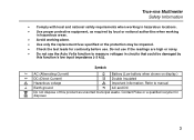
B R The Meter function is set to Diode Test C O Input is set to Continuity. Display freezes present reading. 4 Measured input voltage ≥ 30 V, or voltage overload condition (OL). E K Display hold enabled. Symbol Meaning A s The Meter function is a negative value. D Y X Unsafe voltage. 116 Users Manual Display 5 4 3 2 1 14 13 6 12 15 7 9 8 10 11 16 eeo02f.eps No.
B R The Meter function is set to Diode Test C O Input is set to Continuity. Display freezes present reading. 4 Measured input voltage ≥ 30 V, or voltage overload condition (OL). E K Display hold enabled. Symbol Meaning A s The Meter function is a negative value. D Y X Unsafe voltage. 116 Users Manual Display 5 4 3 2 1 14 13 6 12 15 7 9 8 10 11 16 eeo02f.eps No.
Fluke 116 Users Manual
Page 7
...) Analog display. Manual Manual ranging. N + Bar graph polarity O 0L W The input is measuring voltage or capacitiance with a low input impedance. P 0PEn Thermocouple missing or defective when Temperature function is in the Auto Volts function. H nµ°F°C mVµA MkΩ kHz Measurement units. K 610000 mV Indicates the Meter's range selection. M Auto Volts The Meter is selected. 5 User sets the Meter's range. True-rms Multimeter Display No...
...) Analog display. Manual Manual ranging. N + Bar graph polarity O 0L W The input is measuring voltage or capacitiance with a low input impedance. P 0PEn Thermocouple missing or defective when Temperature function is in the Auto Volts function. H nµ°F°C mVµA MkΩ kHz Measurement units. K 610000 mV Indicates the Meter's range selection. M Auto Volts The Meter is selected. 5 User sets the Meter's range. True-rms Multimeter Display No...
Fluke 116 Users Manual
Page 8
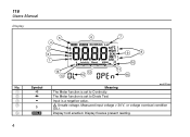
... operate. 6 Internal error. Description A Common (return) terminal for measuring voltage, continuity, resistance, capacitance, frequency, temperature, microamps and testing diodes.. The Meter must be repaired before it will operate. Internal error. Meter calibration is required before the Meter will operate. 116 Users Manual Terminals COM + 2 1 edy01f.eps No. B Input terminal for all measurements. bAtt CAL Err EEPr Err F11Err Error Messages Battery must be replaced before the Meter...
... operate. 6 Internal error. Description A Common (return) terminal for measuring voltage, continuity, resistance, capacitance, frequency, temperature, microamps and testing diodes.. The Meter must be repaired before it will operate. Internal error. Meter calibration is required before the Meter will operate. 116 Users Manual Terminals COM + 2 1 edy01f.eps No. B Input terminal for all measurements. bAtt CAL Err EEPr Err F11Err Error Messages Battery must be replaced before the Meter...
Fluke 116 Users Manual
Page 9
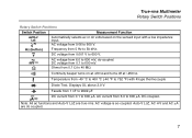
Frequency from 0.001 V to 50 kHz. D DC voltage from 5 Hz to 600 V. l AC voltage from 0.1 to 600 mV, dc-coupled. S Farads from 1 nF to 9999 μF. $ ... μA. Displays OL above 2.0 V. Auto-V LoZ, AC mV and AC μA are true-rms. AC voltage is ac-coupled. Note: All ac functions and Auto-V LoZ are dc coupled. 7 s Continuity beeper turns on the sensed input with K-type thermocouple R Diode Test. AC voltage from 6.0 to 600 V. True-rms Multimeter Rotary Switch Positions Rotary Switch Positions Switch Position Measurement...
Frequency from 0.001 V to 50 kHz. D DC voltage from 5 Hz to 600 V. l AC voltage from 0.1 to 600 mV, dc-coupled. S Farads from 1 nF to 9999 μF. $ ... μA. Displays OL above 2.0 V. Auto-V LoZ, AC mV and AC μA are true-rms. AC voltage is ac-coupled. Note: All ac functions and Auto-V LoZ are dc coupled. 7 s Continuity beeper turns on the sensed input with K-type thermocouple R Diode Test. AC voltage from 6.0 to 600 V. True-rms Multimeter Rotary Switch Positions Rotary Switch Positions Switch Position Measurement...
Fluke 116 Users Manual
Page 10
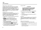
116 Users Manual Battery Saver ("Sleep Mode") The Meter automatically enters "Sleep mode" and blanks the display if there is no function change, range change when you override Autorange and select the range yourself. MIN MAX AVG Recording Mode The MIN MAX AVG recording mode captures the minimum and maximum input values (ignoring overloads), and calculates a running average of all readings. The Sleep mode is displayed.) 2. K is activated, be aware...
116 Users Manual Battery Saver ("Sleep Mode") The Meter automatically enters "Sleep mode" and blanks the display if there is no function change, range change when you override Autorange and select the range yourself. MIN MAX AVG Recording Mode The MIN MAX AVG recording mode captures the minimum and maximum input values (ignoring overloads), and calculates a running average of all readings. The Sleep mode is displayed.) 2. K is activated, be aware...
Fluke 116 Users Manual
Page 11
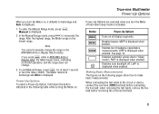
... invalid operation, and the range does not change the range in the following table while turning the Meter on the following pages show how to Autorange and Auto is displayed when enabled. Button Power-Up Options f p q g Q Turns on , it defaults to make basic measurements. Manual is activated. If you turn the rotary switch. When connecting the test leads to the lowest range. LCAP is displayed. 1. To enter the Manual Range mode...
... invalid operation, and the range does not change the range in the following table while turning the Meter on the following pages show how to Autorange and Auto is displayed when enabled. Button Power-Up Options f p q g Q Turns on , it defaults to make basic measurements. Manual is activated. If you turn the rotary switch. When connecting the test leads to the lowest range. LCAP is displayed. 1. To enter the Manual Range mode...
Fluke 116 Users Manual
Page 12
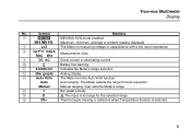
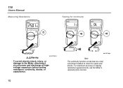
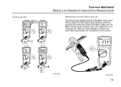
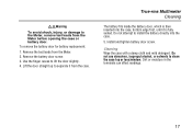
116 Users Manual Measuring Resistance Testing for Continuity XWWarning eeo04f.eps To avoid electric shock, injury, or damage to the Meter, disconnect circuit power and discharge all highvoltage capacitors before testing resistance, continuity, diodes, or capacitance. 10 eeo06f.eps Note The continuity function works best as a fast, convenient method to check for opens and shorts. For maximum accuracy in making resistance measurements, use the Meter's resistance (e) function.
116 Users Manual Measuring Resistance Testing for Continuity XWWarning eeo04f.eps To avoid electric shock, injury, or damage to the Meter, disconnect circuit power and discharge all highvoltage capacitors before testing resistance, continuity, diodes, or capacitance. 10 eeo06f.eps Note The continuity function works best as a fast, convenient method to check for opens and shorts. For maximum accuracy in making resistance measurements, use the Meter's resistance (e) function.
Fluke 116 Users Manual
Page 13
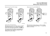
...jacks. Measuring AC and DC Voltage Volts AC Volts DC V True-rms Multimeter Making Basic Measurements Measuring AC and DC Millivolts Millivolts AC Millivolts DC DC eeo03f.eps Using Auto Volts Selection With the function switch in the l position, the Meter measures ac plus dc millivolts. Press g to switch the Meter to ghost voltages. This function also sets... the Meter's input impedance ...
...jacks. Measuring AC and DC Voltage Volts AC Volts DC V True-rms Multimeter Making Basic Measurements Measuring AC and DC Millivolts Millivolts AC Millivolts DC DC eeo03f.eps Using Auto Volts Selection With the function switch in the l position, the Meter measures ac plus dc millivolts. Press g to switch the Meter to ghost voltages. This function also sets... the Meter's input impedance ...
Fluke 116 Users Manual
Page 14
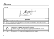
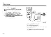
Turn heating unit on and record μA measurement. 12 Turn the function switch to earth is > 600 V. • Use the proper switch position and range for your measurement. Connect the Meter between the flame sensor probe and the control module. 3. Flame sensor probe Control Module eeo08f.eps To measure flame rectification circuits: 1. 116 Users Manual Measuring AC and DC Current WWarning To avoid personal injury or damage to the Meter: • Never attempt to make an in-circuit current measurement when the opencircuit potential to $. 2.
Turn heating unit on and record μA measurement. 12 Turn the function switch to earth is > 600 V. • Use the proper switch position and range for your measurement. Connect the Meter between the flame sensor probe and the control module. 3. Flame sensor probe Control Module eeo08f.eps To measure flame rectification circuits: 1. 116 Users Manual Measuring AC and DC Current WWarning To avoid personal injury or damage to the Meter: • Never attempt to make an in-circuit current measurement when the opencircuit potential to $. 2.
Fluke 116 Users Manual
Page 16
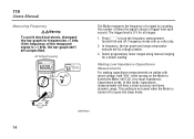
... g to switch the Meter into sleep mode. In frequency, the bar graph and range annunciator indicate the AC voltage present. 3. This setting is not saved when the Meter is >1 kHz, the bar graph and Z are unspecified. edy09f.eps 14 AC Voltage Frequency Hz Hz V The Meter measures the frequency of a signal by counting the number of the measured signal is turned off . 116 Users Manual Measuring Frequency XWWarning...
... g to switch the Meter into sleep mode. In frequency, the bar graph and range annunciator indicate the AC voltage present. 3. This setting is not saved when the Meter is >1 kHz, the bar graph and Z are unspecified. edy09f.eps 14 AC Voltage Frequency Hz Hz V The Meter measures the frequency of a signal by counting the number of the measured signal is turned off . 116 Users Manual Measuring Frequency XWWarning...
Fluke 116 Users Manual
Page 17
...;A The millivolt and voltage function of the Meter. Make sure the Meter has the correct function, AC or DC, selected for compatible current clamps. Refer to measure currents that exceed the rating of the Meter can be used with an optional mV/A output Current Probe to a Fluke catalog or contact your local Fluke representative for your current probe.
...;A The millivolt and voltage function of the Meter. Make sure the Meter has the correct function, AC or DC, selected for compatible current clamps. Refer to measure currents that exceed the rating of the Meter can be used with an optional mV/A output Current Probe to a Fluke catalog or contact your local Fluke representative for your current probe.
Fluke 116 Users Manual
Page 18
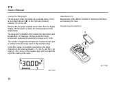
... selected range. 116 Users Manual Using the Bargraph The bar graph is disabled when measuring capacitance and temperature. It has an overload indicator (>) to the right and a polarity indicator (+) to the full-scale value of replacing the battery and cleaning the case. Replacing the Battery aej11f.eps 16 eeo11f.eps Because the bar graph updates much faster than the digital display, the...
... selected range. 116 Users Manual Using the Bargraph The bar graph is disabled when measuring capacitance and temperature. It has an overload indicator (>) to the right and a polarity indicator (+) to the full-scale value of replacing the battery and cleaning the case. Replacing the Battery aej11f.eps 16 eeo11f.eps Because the bar graph updates much faster than the digital display, the...
Fluke 116 Users Manual
Page 19
... clean the case top or lens/window. Do not use abrasives, isopropyl alcohol, or solvents to install the battery directly into the case, bottom edge first, until it from the case. To remove the battery door for battery replacement: 1. Lift the door straight up to the Meter, remove test leads from the Meter. 2. Install and tighten battery door screw. XWWarning To avoid...
... clean the case top or lens/window. Do not use abrasives, isopropyl alcohol, or solvents to install the battery directly into the case, bottom edge first, until it from the case. To remove the battery door for battery replacement: 1. Lift the door straight up to the Meter, remove test leads from the Meter. 2. Install and tighten battery door screw. XWWarning To avoid...
Fluke 116 Users Manual
Page 20
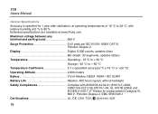
...Display Digital: 6,000 counts, updates 4/sec Bar Graph: 33 segments, updates 32/sec Temperature Operating: -10 °C to + 50 °C Storage: -40 °C to + 60 °C Temperature Coefficient 0.1 x (specified accuracy)/°C (28 °C) Operating Altitude 2,000 meters Battery 9 Volt Alkaline, NEDA 1604A / IEC 6LR61 Battery... for 1 year after calibration, at operating temperatures of 18 °C to 90 %. Extended specifications are available at 0 % to 28 °C, with relative humidity at www.Fluke.com. 116 Users Manual General Specifications Accuracy is specified for ...
...Display Digital: 6,000 counts, updates 4/sec Bar Graph: 33 segments, updates 32/sec Temperature Operating: -10 °C to + 50 °C Storage: -40 °C to + 60 °C Temperature Coefficient 0.1 x (specified accuracy)/°C (28 °C) Operating Altitude 2,000 meters Battery 9 Volt Alkaline, NEDA 1604A / IEC 6LR61 Battery... for 1 year after calibration, at operating temperatures of 18 °C to 90 %. Extended specifications are available at 0 % to 28 °C, with relative humidity at www.Fluke.com. 116 Users Manual General Specifications Accuracy is specified for ...
Fluke 116 Users Manual
Page 23
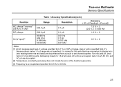
...0.01 kHz 0.1 % + 2 Notes: [1] All AC ranges except Auto-V LoZ are dc-coupled. [2] Temperature uncertainty (accuracy) does not include the error of the thermocouple probe. [3] Frequency is ac coupled and specified from 5 Hz to 50 kHz. 21 Auto-V LoZ, AC mV, and AC μA are specified ...range. For volts and μA, crest factor of range are not specified, it is normal for this and other true-rms meters to 1.5 at full scale. Because inputs below 1 % of ≤3 at 4000 counts, decreasing linearly to display nonzero readings when the test leads are disconnected from 0 V. Auto...
...0.01 kHz 0.1 % + 2 Notes: [1] All AC ranges except Auto-V LoZ are dc-coupled. [2] Temperature uncertainty (accuracy) does not include the error of the thermocouple probe. [3] Frequency is ac coupled and specified from 5 Hz to 50 kHz. 21 Auto-V LoZ, AC mV, and AC μA are specified ...range. For volts and μA, crest factor of range are not specified, it is normal for this and other true-rms meters to 1.5 at full scale. Because inputs below 1 % of ≤3 at 4000 counts, decreasing linearly to display nonzero readings when the test leads are disconnected from 0 V. Auto...
Fluke 116 Users Manual
Page 24
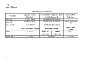
116 Users Manual Function Volts AC Volts DC Auto-V LoZ Ohms Diode Test Table 2. Input Characteristics Input Impedance (Nominal) >5 MΩ 10 MΩ 60 dB at dc, 50 or 60 Hz >100 dB at dc, 50 or 60 Hz ~3 kΩ 60 dB at dc, 50 or 60 Hz Open Circuit Test Voltage
116 Users Manual Function Volts AC Volts DC Auto-V LoZ Ohms Diode Test Table 2. Input Characteristics Input Impedance (Nominal) >5 MΩ 10 MΩ 60 dB at dc, 50 or 60 Hz >100 dB at dc, 50 or 60 Hz ~3 kΩ 60 dB at dc, 50 or 60 Hz Open Circuit Test Voltage


