Operation Manual
Page 5
WARNING The connection of a non-shielded printer interface cable to this printer will be required to correct the interference at his own expense. FOR CANADIAN USERS This Class A digital apparatus meets all requirements of the FCC Rules. You are designed to ... For American Users This equipment has been tested and found to comply with the instruction manual, may cause interference levels which case the user will invalidate the FCC Verification of this equipment in a residential area is operated in a commercial environment. These limits are cautioned that changes or modifications ...
WARNING The connection of a non-shielded printer interface cable to this printer will be required to correct the interference at his own expense. FOR CANADIAN USERS This Class A digital apparatus meets all requirements of the FCC Rules. You are designed to ... For American Users This equipment has been tested and found to comply with the instruction manual, may cause interference levels which case the user will invalidate the FCC Verification of this equipment in a residential area is operated in a commercial environment. These limits are cautioned that changes or modifications ...
Operation Manual
Page 6
...Connecting the Printer to the Computer 1-4 TM-U200B 1-4 TM-U200PB 1-5 Connecting the Printer to the Drawer 1-6 Grounding the Printer 1-8 Connecting the Power Supply 1-9 Installing the Ribbon Cassette 1-11 Installing the Paper Roll 1-13 Running the Self Test 1-17 Setting the DIP Switches 1-18 Using the Power Switch Cover 1-21 Affixing the Fastening Tape (Option 1-22 Chapter 2 Using the Printer Operating the Control Panel 2-1 Switch 2-1 Button 2-1 Indicator lights 2-2 Chapter 3 Troubleshooting Troubleshooting 3-1 General problems 3-1 Printing problems 3-1 Removing jammed paper...
...Connecting the Printer to the Computer 1-4 TM-U200B 1-4 TM-U200PB 1-5 Connecting the Printer to the Drawer 1-6 Grounding the Printer 1-8 Connecting the Power Supply 1-9 Installing the Ribbon Cassette 1-11 Installing the Paper Roll 1-13 Running the Self Test 1-17 Setting the DIP Switches 1-18 Using the Power Switch Cover 1-21 Affixing the Fastening Tape (Option 1-22 Chapter 2 Using the Printer Operating the Control Panel 2-1 Switch 2-1 Button 2-1 Indicator lights 2-2 Chapter 3 Troubleshooting Troubleshooting 3-1 General problems 3-1 Printing problems 3-1 Removing jammed paper...
Operation Manual
Page 7
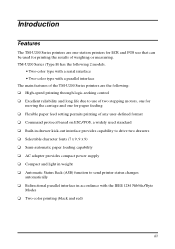
... two drawers t Selectable character fonts (7 x 9, 9 x 9) t Semi-automatic paper loading capability t AC adapter provides compact power supply t Compact and light in weight t Automatic Status Back (ASB) function to use that can be used for paper feeding t Flexible paper feed setting permits printing of weighing or measuring. TM-U200 Series (Type B) has the following : t High-speed printing through logic-seeking control t Excellent reliability and long life due to send printer status changes automatically t Bidirectional parallel interface in accordance with...
... two drawers t Selectable character fonts (7 x 9, 9 x 9) t Semi-automatic paper loading capability t AC adapter provides compact power supply t Compact and light in weight t Automatic Status Back (ASB) function to use that can be used for paper feeding t Flexible paper feed setting permits printing of weighing or measuring. TM-U200 Series (Type B) has the following : t High-speed printing through logic-seeking control t Excellent reliability and long life due to send printer status changes automatically t Bidirectional parallel interface in accordance with...
Operation Manual
Page 13
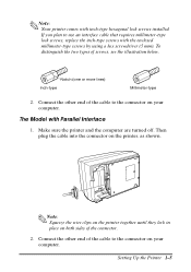
... lines) Inch-type Millimeter-type 2. The Model with the enclosed millimeter-type screws by using a hex screwdriver (5 mm). Note: Squeeze the wire clips on the printer together until they lock in place on your computer. Connect the other end of the cable to use an interface cable that requires millimeter-type lock screws, replace the inch-type screws with Parallel Interface 1. Make sure the printer and the computer are turned...
... lines) Inch-type Millimeter-type 2. The Model with the enclosed millimeter-type screws by using a hex screwdriver (5 mm). Note: Squeeze the wire clips on the printer together until they lock in place on your computer. Connect the other end of the cable to use an interface cable that requires millimeter-type lock screws, replace the inch-type screws with Parallel Interface 1. Make sure the printer and the computer are turned...
Operation Manual
Page 14
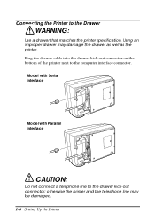
Using an improper drawer may be damaged. 1-6 Setting Up the Printer Connecting the Printer to the drawer kick-out connector; otherwise the printer and the telephone line may damage the drawer as well as the printer. Model with Serial Interface Model with Parallel Interface CAUTION: Do not connect a telephone line to the Drawer WARNING: Use a drawer that matches the printer specification. Plug the drawer cable into the drawer kick-out connector on the bottom of the printer next to the computer interface connector.
Using an improper drawer may be damaged. 1-6 Setting Up the Printer Connecting the Printer to the drawer kick-out connector; otherwise the printer and the telephone line may damage the drawer as well as the printer. Model with Serial Interface Model with Parallel Interface CAUTION: Do not connect a telephone line to the Drawer WARNING: Use a drawer that matches the printer specification. Plug the drawer cable into the drawer kick-out connector on the bottom of the printer next to the computer interface connector.
Operation Manual
Page 20
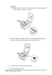
Close the printer cover. 1-12 Setting Up the Printer Close the auto cutter by using the tab. 7. Note: Make sure the ribbon is installed between the print head and the platen without wrinkles or creases. 5. Turn the ribbon cassette's knob 5 or 6 times in the direction of the arrow again to take up any slack in the ribbon. 6.
Close the printer cover. 1-12 Setting Up the Printer Close the auto cutter by using the tab. 7. Note: Make sure the ribbon is installed between the print head and the platen without wrinkles or creases. 5. Turn the ribbon cassette's knob 5 or 6 times in the direction of the arrow again to take up any slack in the ribbon. 6.
Operation Manual
Page 21
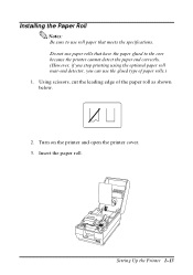
Turn on the printer and open the printer cover. 3. Insert the paper roll. Setting Up the Printer 1-13 Do not use paper rolls that have the paper glued to use the glued type of the paper roll as shown below. 2. Using scissors, cut the leading edge of paper rolls.) 1. Installing the Paper Roll Notes: Be sure to the core because the printer cannot detect the paper end correctly. (However, if you stop printing using the optional paper roll near-end detector, you can use roll paper that meets the specifications.
Turn on the printer and open the printer cover. 3. Insert the paper roll. Setting Up the Printer 1-13 Do not use paper rolls that have the paper glued to use the glued type of the paper roll as shown below. 2. Using scissors, cut the leading edge of paper rolls.) 1. Installing the Paper Roll Notes: Be sure to the core because the printer cannot detect the paper end correctly. (However, if you stop printing using the optional paper roll near-end detector, you can use roll paper that meets the specifications.
Operation Manual
Page 24
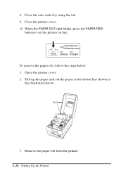
Open the printer cover. 2. Close the printer cover. 10. Pull up the paper and cut the paper at the dotted line shown in the illustration below . 1. Remove the paper roll from the printer. 1-16 Setting Up the Printer Close the auto cutter by using the tab. 9. To remove the paper roll, follow the steps below . Cut here 3. 8. When the PAPER OUT light blinks, press the PAPER FEED button to set the printer on line.
Open the printer cover. 2. Close the printer cover. 10. Pull up the paper and cut the paper at the dotted line shown in the illustration below . 1. Remove the paper roll from the printer. 1-16 Setting Up the Printer Close the auto cutter by using the tab. 9. To remove the paper roll, follow the steps below . Cut here 3. 8. When the PAPER OUT light blinks, press the PAPER FEED button to set the printer on line.
Operation Manual
Page 25
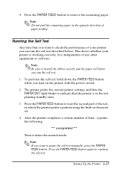
... PAPER OUT light blinks to indicate that you want to pause the self test manually, press the PAPER FEED button. Setting Up the Printer 1-17 4. Note: Do not pull the remaining paper in the opposite direction of the test, in which the printer prints a pattern using the built-in the test printing standby state. 3. Press the PAPER FEED button again to remove the remaining paper. This shows whether your printer you turn on the printer with the power switch...
... PAPER OUT light blinks to indicate that you want to pause the self test manually, press the PAPER FEED button. Setting Up the Printer 1-17 4. Note: Do not pull the remaining paper in the opposite direction of the test, in which the printer prints a pattern using the built-in the test printing standby state. 3. Press the PAPER FEED button again to remove the remaining paper. This shows whether your printer you turn on the printer with the power switch...

Operation Manual
Page 27
Setting Up the Printer 1-19 Model with Serial Interface DIP-Switch Functions DIP Switch Set 1 Switch Function 1-1 Data reception error 1-2 Receive buffer capacity 1-3 Handshaking 1-4 Word length 1-5 Parity check 1-6 Parity selection 1-7 Baud rate 1-8 Busy condition ON OFF Ignored Prints "?" 40 bytes Approximately 1K byte XON/XOFF DTR/DSR 7 bits 8 bits Yes No Even Odd 4800 BPS 9600 BPS Receive buffer full Off line or receive buffer full DIP Switch Set 2 Switch Function ON OFF 2-1 Print column selection 42/35 7 × 9 font/9 ×...
Setting Up the Printer 1-19 Model with Serial Interface DIP-Switch Functions DIP Switch Set 1 Switch Function 1-1 Data reception error 1-2 Receive buffer capacity 1-3 Handshaking 1-4 Word length 1-5 Parity check 1-6 Parity selection 1-7 Baud rate 1-8 Busy condition ON OFF Ignored Prints "?" 40 bytes Approximately 1K byte XON/XOFF DTR/DSR 7 bits 8 bits Yes No Even Odd 4800 BPS 9600 BPS Receive buffer full Off line or receive buffer full DIP Switch Set 2 Switch Function ON OFF 2-1 Print column selection 42/35 7 × 9 font/9 ×...

Operation Manual
Page 28
... the DIP switch cover and secure it with Parallel Interface DIP-Switch Functions DIP Switch Set 1 Switch Function 1-1 Auto-line feed 1-2 Receive buffer capacity 1-3 Undefined 1-4 Undefined 1-5 Undefined 1-6 Undefined 1-7 Undefined 1-8 Handshaking (BUSY condition) ON Enabled 40 bytes OFF Disabled Approximately 1K byte Receive buffer full or reading data Off line, receive buffer full, or reading data DIP Switch Set 2 Switch Function ON OFF 2-1 Print column selection 42/35 7 × 9 font/9 × 9 font 40/33 2-2 Internal use Setting must not be changed. (Fixed...
... the DIP switch cover and secure it with Parallel Interface DIP-Switch Functions DIP Switch Set 1 Switch Function 1-1 Auto-line feed 1-2 Receive buffer capacity 1-3 Undefined 1-4 Undefined 1-5 Undefined 1-6 Undefined 1-7 Undefined 1-8 Handshaking (BUSY condition) ON Enabled 40 bytes OFF Disabled Approximately 1K byte Receive buffer full or reading data Off line, receive buffer full, or reading data DIP Switch Set 2 Switch Function ON OFF 2-1 Print column selection 42/35 7 × 9 font/9 × 9 font 40/33 2-2 Internal use Setting must not be changed. (Fixed...
Operation Manual
Page 31
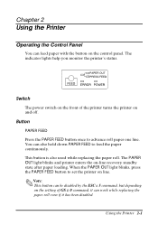
... after paper loading. Button PAPER FEED Press the PAPER FEED button once to set the printer on and off. The PAPER OUT light blinks and printer enters the on the control panel. Using the Printer 2-1 Switch The power switch on the front of GS z 0 command, it can work while replacing the paper roll even if it has been disabled. You can be disabled by the ESC c 5 command, but depending on the setting of the printer turns the printer on line. Note: This button can...
... after paper loading. Button PAPER FEED Press the PAPER FEED button once to set the printer on and off. The PAPER OUT light blinks and printer enters the on the control panel. Using the Printer 2-1 Switch The power switch on the front of GS z 0 command, it can work while replacing the paper roll even if it has been disabled. You can be disabled by the ESC c 5 command, but depending on the setting of the printer turns the printer on line. Note: This button can...
Operation Manual
Page 32
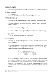
... instructions on . t In the self-test standby mode t In the on-line recovery standby state after semi-auto loading Note: The paper near the end. Then turn the printer off line. The blinking pattern shown below indicates that the temperature of the print head is an option. Approximately 160 ms If the printer stops working and the ERROR light is on page 3-3, if necessary. then contact a qualified service person. 2-2 Using the Printer...
... instructions on . t In the self-test standby mode t In the on-line recovery standby state after semi-auto loading Note: The paper near the end. Then turn the printer off line. The blinking pattern shown below indicates that the temperature of the print head is an option. Approximately 160 ms If the printer stops working and the ERROR light is on page 3-3, if necessary. then contact a qualified service person. 2-2 Using the Printer...
Operation Manual
Page 34
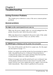
... not work, unplug the power supply cord from the outlet immediately. Troubleshooting 3-1 Printing problems The ERROR light is supplied to the power outlet. Make sure that power is blinking and the printer does not print. First, turn it back on after about 10 seconds. If the print head is no paper jam and the print head is controlled by a switch or timer, use another outlet. Then contact a qualified service person. Make sure the power supply cables are...
... not work, unplug the power supply cord from the outlet immediately. Troubleshooting 3-1 Printing problems The ERROR light is supplied to the power outlet. Make sure that power is blinking and the printer does not print. First, turn it back on after about 10 seconds. If the print head is no paper jam and the print head is controlled by a switch or timer, use another outlet. Then contact a qualified service person. Make sure the power supply cables are...

Operation Manual
Page 35
... self test does not work, contact your dealer or a qualified service person. Check the connection at both the printer and the computer. 2. You can print the printer's interface settings using the self test. Replace the ribbon cassette as the computer's. The ribbon cassette may be installed properly. The printout is faint. The ribbon may not be worn out. The ERROR light is off, but nothing is printed. Make sure that the printer works properly. Replace the ribbon...
... self test does not work, contact your dealer or a qualified service person. Check the connection at both the printer and the computer. 2. You can print the printer's interface settings using the self test. Replace the ribbon cassette as the computer's. The ribbon cassette may be installed properly. The printout is faint. The ribbon may not be worn out. The ERROR light is off, but nothing is printed. Make sure that the printer works properly. Replace the ribbon...
Operation Manual
Page 36
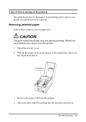
Allow it to clear a paper jam: CAUTION: The print head becomes very hot during printing. Open the auto cutter by pulling the tab up the paper and cut the paper at the dotted line shown in the printout. Troubleshooting 3-3 A line of dots is missing in the illustration below. Remove the paper roll from the printer. 4. Pull up and toward you reach into the printer. 1. Stop printing and contact your dealer or a qualified service person. Open the printer cover. 2. Removing jammed paper Follow these steps to cool before you . The print head may be damaged. Cut here 3.
Allow it to clear a paper jam: CAUTION: The print head becomes very hot during printing. Open the auto cutter by pulling the tab up the paper and cut the paper at the dotted line shown in the printout. Troubleshooting 3-3 A line of dots is missing in the illustration below. Remove the paper roll from the printer. 4. Pull up and toward you reach into the printer. 1. Stop printing and contact your dealer or a qualified service person. Open the printer cover. 2. Removing jammed paper Follow these steps to cool before you . The print head may be damaged. Cut here 3.

Operation Manual
Page 39
Note: Do not pull the jammed paper in the direction opposite of paper feeding. 11. Replace the print head cover and secure it with the screw. 12. Replace the ribbon cassette and close the auto cutter 3-6 Troubleshooting Remove all the jammed paper. Lift up the print head cover. 10. 9.
Note: Do not pull the jammed paper in the direction opposite of paper feeding. 11. Replace the print head cover and secure it with the screw. 12. Replace the ribbon cassette and close the auto cutter 3-6 Troubleshooting Remove all the jammed paper. Lift up the print head cover. 10. 9.
Operation Manual
Page 41
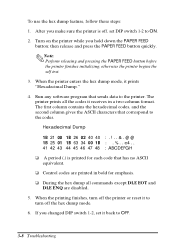
... you changed DIP switch 1-2, set DIP switch 1-2 to turn off the printer or reset it prints "Hexadecimal Dump." 4. The first column contains the hexadecimal codes, and the second column gives the ASCII characters that has no ASCII equivalent. When the printing finishes, turn off the hex dump mode. 6. To use the hex dump feature, follow these steps: 1. Note: Perform releasing and pressing the PAPER FEED button before the printer finishes initializing; Turn on the printer while you make...
... you changed DIP switch 1-2, set DIP switch 1-2 to turn off the printer or reset it prints "Hexadecimal Dump." 4. The first column contains the hexadecimal codes, and the second column gives the ASCII characters that has no ASCII equivalent. When the printing finishes, turn off the hex dump mode. 6. To use the hex dump feature, follow these steps: 1. Note: Perform releasing and pressing the PAPER FEED button before the printer finishes initializing; Turn on the printer while you make...

Operation Manual
Page 42
... described above is not guaranteed. Character spacing (default) Fonts A and B: See table on page 4-2. Reference Information 4-1 Chapter 4 Reference Information Printing Specifications Printing method: Serial impact dot-matrix Head wire configuration: 9-pin serial configuration Printing direction: Bi-directional, logic-seeking Characters/line (default): See table on page 4-2. Printing speed: Approximately 3.5 lines/second (40 columns, 16 characters/inch) Approximately 6.4 lines/second (16 columns, 16 characters/inch) (excluding data transmission time and processing time...
... described above is not guaranteed. Character spacing (default) Fonts A and B: See table on page 4-2. Reference Information 4-1 Chapter 4 Reference Information Printing Specifications Printing method: Serial impact dot-matrix Head wire configuration: 9-pin serial configuration Printing direction: Bi-directional, logic-seeking Characters/line (default): See table on page 4-2. Printing speed: Approximately 3.5 lines/second (40 columns, 16 characters/inch) Approximately 6.4 lines/second (16 columns, 16 characters/inch) (excluding data transmission time and processing time...

Operation Manual
Page 43
... dots 33 13.3 9 x 9 Graphics 2.0 x 3.1 0 33 13.3 ANK 1.2 x 3.1 2 half dots 42 17.8 7 x 9 Graphics 1.6 x 3.1 0 42 17.8 ANK 1.6 x 3.1 2 half dots 35 14.5 9 x 9 Graphics 1.9 x 3.1 0 35 14.5 CPL = Characters per line CPI = Characters per inch LPS = Lines per second Notes: • The default is 7 x 9 with 3 -dot spacing in half-dot units. • 7 x 9 with 2 -dot spacing in half-dot units and 9 x 9 with 2 -dot spacing in half dot units) See table below. dot units depend on the DIP switch setting. 4-2 Reference...
... dots 33 13.3 9 x 9 Graphics 2.0 x 3.1 0 33 13.3 ANK 1.2 x 3.1 2 half dots 42 17.8 7 x 9 Graphics 1.6 x 3.1 0 42 17.8 ANK 1.6 x 3.1 2 half dots 35 14.5 9 x 9 Graphics 1.9 x 3.1 0 35 14.5 CPL = Characters per line CPI = Characters per inch LPS = Lines per second Notes: • The default is 7 x 9 with 3 -dot spacing in half-dot units. • 7 x 9 with 2 -dot spacing in half-dot units and 9 x 9 with 2 -dot spacing in half dot units) See table below. dot units depend on the DIP switch setting. 4-2 Reference...


