User Manual
Page 5
...is assumed with respect to the use of the information contained herein. Government Printing Office, Washington, DC 20402. All rights reserved. No part of a non-shielded printer interface cable to provide reasonable protection against such interference in any liability assumed...It has been type tested and found to unused interfaces. Epson is a registered trademark of this printer. Centronics is a registered trademark of Seiko Epson Corporation. If this book, Seiko Epson Corporation assumes no responsibility for use or combination of any Epson printer with any means, ...
...is assumed with respect to the use of the information contained herein. Government Printing Office, Washington, DC 20402. All rights reserved. No part of a non-shielded printer interface cable to provide reasonable protection against such interference in any liability assumed...It has been type tested and found to unused interfaces. Epson is a registered trademark of this printer. Centronics is a registered trademark of Seiko Epson Corporation. If this book, Seiko Epson Corporation assumes no responsibility for use or combination of any Epson printer with any means, ...
User Manual
Page 6
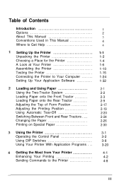
...Printing on Special Paper Using the Printer Operating the Control Panel Using DIP Switches Using Your Printer With Application Programs . .. Table of Contents Introduction Options About This Manual Conventions Used in This Manual Where to Get Help Setting Up the Printer Unpacking the Printer Choosing a Place for the Printer A Look at Your Printer Assembling the Printer Testing the Printer... Connecting the Printer to the Printer 1 2 ...
...Printing on Special Paper Using the Printer Operating the Control Panel Using DIP Switches Using Your Printer With Application Programs . .. Table of Contents Introduction Options About This Manual Conventions Used in This Manual Where to Get Help Setting Up the Printer Unpacking the Printer Choosing a Place for the Printer A Look at Your Printer Assembling the Printer Testing the Printer... Connecting the Printer to the Printer 1 2 ...
User Manual
Page 27
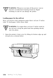
the self test to load continuous paper that is at least 15 inches wide for the self test Next, you need to keep the print head from printing directly 77 onto the platen. 1. Rapid switching on and off the power, wait at least five seconds before turning it back on. Open the printer's front cover by lifting its bottom edge up and toward you turn off can damage the printer. Loading paper for I. To load paper, follow these steps: WARNING: Use paper that is at least 15 inches wide. WARNING: Whenever you , as shown below.
the self test to load continuous paper that is at least 15 inches wide for the self test Next, you need to keep the print head from printing directly 77 onto the platen. 1. Rapid switching on and off the power, wait at least five seconds before turning it back on. Open the printer's front cover by lifting its bottom edge up and toward you turn off can damage the printer. Loading paper for I. To load paper, follow these steps: WARNING: Use paper that is at least 15 inches wide. WARNING: Whenever you , as shown below.

User Manual
Page 33
... self test The self test prints out the settings of a typical self test printout in high-speed draft. 2. To run in high-speed draft mode, follow these steps: Caution: Always use paper that is part of the printer's DIP switches and the characters in the printer's memory. After printing starts, release the button. If the test results are...
... self test The self test prints out the settings of a typical self test printout in high-speed draft. 2. To run in high-speed draft mode, follow these steps: Caution: Always use paper that is part of the printer's DIP switches and the characters in the printer's memory. After printing starts, release the button. If the test results are...

User Manual
Page 35
... parallel interface is required by your computer, check your computer. Connecting the Printer to Your Computer If the self test printed correctly, you are not sure which one of interface, you are now ready to connect the printer to connect the printer immediately. If you need to change the DIP switch settings as shown in...
... parallel interface is required by your computer, check your computer. Connecting the Printer to Your Computer If the self test printed correctly, you are not sure which one of interface, you are now ready to connect the printer to connect the printer immediately. If you need to change the DIP switch settings as shown in...

User Manual
Page 75
Chapter 3 Using the Printer Operating the Control Panel 3-2 Control panel indicator lights 3-2 Control panel buttons 3-4 Other control panel features 3-7 Using DIP Switches 3-8 Changing DIP switch settings 3-8 DIP switch tables 3-... quality or draft mode 3-15 International character sets 3-16 Page length 3-17 Printing speed in draft mode 3-17 Skip over perforation 3-18 Auto line feed 3-18 Interface type and parity 3-19 Baud rate 3-19 Using Your Printer With Application Programs 3-20 A quick test 3-20 Using word processors 3-21 Using spreadsheets 3-21 Using the...
Chapter 3 Using the Printer Operating the Control Panel 3-2 Control panel indicator lights 3-2 Control panel buttons 3-4 Other control panel features 3-7 Using DIP Switches 3-8 Changing DIP switch settings 3-8 DIP switch tables 3-... quality or draft mode 3-15 International character sets 3-16 Page length 3-17 Printing speed in draft mode 3-17 Skip over perforation 3-18 Auto line feed 3-18 Interface type and parity 3-19 Baud rate 3-19 Using Your Printer With Application Programs 3-20 A quick test 3-20 Using word processors 3-21 Using spreadsheets 3-21 Using the...

User Manual
Page 78
...LINE button and the LINE FEED/LOAD button. You can receive and print data from the computer. The FORM FEED button lets you perform printer operations quickly and easily. See Chapter 2 for more information on and the printer can also press the ON LINE button to exit the tear-off line...r-l PAPER SELECT FRONT/REAR The ON LINE button controls the printer's on line or take it off line. Press this feature, press the button when the printer is off mode. When you can also be used to run the printer's self test. Control panel buttons The control panel buttons let you advance ...
...LINE button and the LINE FEED/LOAD button. You can receive and print data from the computer. The FORM FEED button lets you perform printer operations quickly and easily. See Chapter 2 for more information on and the printer can also press the ON LINE button to exit the tear-off line...r-l PAPER SELECT FRONT/REAR The ON LINE button controls the printer's on line or take it off line. Press this feature, press the button when the printer is off mode. When you can also be used to run the printer's self test. Control panel buttons The control panel buttons let you advance ...

User Manual
Page 81
... button when labels are sent to several special functions. This feature prints the codes that advanced users can turn on the printer, you switch between the computer and printer. Using the Printer 3-7 The self test prints the current DIP switch settings and the characters in the printer is off line. Self By holding down the LINE FEED...
... button when labels are sent to several special functions. This feature prints the codes that advanced users can turn on the printer, you switch between the computer and printer. Using the Printer 3-7 The self test prints the current DIP switch settings and the characters in the printer is off line. Self By holding down the LINE FEED...

User Manual
Page 94
... one of the following, listed in order of the printer's features. If the document doesn't print correctly, recheck the program's printer selection and installation 3-20 Using the Printer If your application program has a printer selection menu, simply choose the DFX-5000 from . A quick test After setting up and tested the printer, you can start using it with your application programs...
... one of the following, listed in order of the printer's features. If the document doesn't print correctly, recheck the program's printer selection and installation 3-20 Using the Printer If your application program has a printer selection menu, simply choose the DFX-5000 from . A quick test After setting up and tested the printer, you can start using it with your application programs...

User Manual
Page 143
...several minutes until the print head cools. The paper may be jammed. Printing resumes when the head cools. If the printer still does not print, disconnect the printer from the computer and try to a qualified service person. If the self test does not work, contact your Epson dealer. This problem... is working and the problem probably lies in Chapter 1. If the printer stops and the beeper sounds, turn the printer off the printer, remove the protective materials, and turn it to print again. Remove the ...
...several minutes until the print head cools. The paper may be jammed. Printing resumes when the head cools. If the printer still does not print, disconnect the printer from the computer and try to a qualified service person. If the self test does not work, contact your Epson dealer. This problem... is working and the problem probably lies in Chapter 1. If the printer stops and the beeper sounds, turn the printer off the printer, remove the protective materials, and turn it to print again. Remove the ...

User Manual
Page 145
...the interface board are using an optional interface board, make sure that DIP switches 2-5 and 2-6 are set according to the printer in Chapter 3. Troubleshooting 7-5 l If the printing is parallel or serial. Also, for more information on DIP switch settings for your software is correctly set for parallel, regardless...board is too high or low on the page, adjust it by running the self test. (See Chapter 1.) l If you specify continuous-feed paper as the type of the cable between the printer and the computer. Also, make sure that the DIP switches on adjusting the top...
...the interface board are using an optional interface board, make sure that DIP switches 2-5 and 2-6 are set according to the printer in Chapter 3. Troubleshooting 7-5 l If the printing is parallel or serial. Also, for more information on DIP switch settings for your software is correctly set for parallel, regardless...board is too high or low on the page, adjust it by running the self test. (See Chapter 1.) l If you specify continuous-feed paper as the type of the cable between the printer and the computer. Also, make sure that the DIP switches on adjusting the top...
User Manual
Page 218
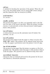
standby position The position the paper is run, the printer prints out its ROM. user-defined characters Characters that the printer recognizes as download characters. tear-off position The position the printer feeds the paper to this position when it automatically reverses the previously loaded paper back ... first printable line. tear-off feature. GL-10 Glossary See automatic tear-off edge. When the printer switches tractors, it loads the paper. When the self test is in its current DIP switch settings and the characters that lets you manually load it onto the...
standby position The position the paper is run, the printer prints out its ROM. user-defined characters Characters that the printer recognizes as download characters. tear-off position The position the printer feeds the paper to this position when it automatically reverses the previously loaded paper back ... first printable line. tear-off feature. GL-10 Glossary See automatic tear-off edge. When the printer switches tractors, it loads the paper. When the self test is in its current DIP switch settings and the characters that lets you manually load it onto the...

User Manual
Page 221
...tractor, loading, 2-9-13 Ribbon installing, l-l0, 14 replacing, 5-3-7 Ribbon guide, 1-11, 1-13 RS-232C, 1-24 S Self test, 1-15, 24 Sending commands to the printer, 4-8-13 Serial interface connecting, 1-28-31 DIP switch settings, 3-19 pin assignments, B-12 specifications, B-11 Setting up, 1-2 ..., character, 4-5-6 Skip over perforation, 3-18 Software. See Application programs Solutions, 7-2-6 Special paper, printing on, 2-30-31 Specifications, B-2-14 Spreadsheets, 3-21-22 Stand, printer, 1-5 Subscripts, 4-7 Superscripts, 4-7 Switches, DIP, 3-8-19 T Tear off button, 3-5 Tear off light, 3-3 Tear-...
...tractor, loading, 2-9-13 Ribbon installing, l-l0, 14 replacing, 5-3-7 Ribbon guide, 1-11, 1-13 RS-232C, 1-24 S Self test, 1-15, 24 Sending commands to the printer, 4-8-13 Serial interface connecting, 1-28-31 DIP switch settings, 3-19 pin assignments, B-12 specifications, B-11 Setting up, 1-2 ..., character, 4-5-6 Skip over perforation, 3-18 Software. See Application programs Solutions, 7-2-6 Special paper, printing on, 2-30-31 Specifications, B-2-14 Spreadsheets, 3-21-22 Stand, printer, 1-5 Subscripts, 4-7 Superscripts, 4-7 Switches, DIP, 3-8-19 T Tear off button, 3-5 Tear off light, 3-3 Tear-...

Service Manual
Page 3
... FROM AVAILABLE POWER SOURCE, DO NOT CONNECT IT TO THE POWER SOURCE. 3. ALWAYS VERIFY THAT THE EPSON PRODUCT HAS BEEN DISCONNECTED FROM THE POWER SOURCE BEFORE REMOVING OR REPLACING PRINTED CIRCUIT BOARDS AND/OR INDIVIDUAL CHIPS. 4. DANGER Signals a precaution which , if ignored, could result ...PERIPHERAL DEVICES PERFORMING ANY MAINTENANCE OR REPAIR PROCEDURE. 2. Great caution should always be exercised in damage to equipment. ii -. WHEN PERFORMING TESTING AS DICTATED WITHIN THIS MANUAL, DO NOT CONNECT THE UNIT TO A POWER SOURCE UNTIL INSTRUCTED TO DO SO. WHEN THE POWER SUPPLY...
... FROM AVAILABLE POWER SOURCE, DO NOT CONNECT IT TO THE POWER SOURCE. 3. ALWAYS VERIFY THAT THE EPSON PRODUCT HAS BEEN DISCONNECTED FROM THE POWER SOURCE BEFORE REMOVING OR REPLACING PRINTED CIRCUIT BOARDS AND/OR INDIVIDUAL CHIPS. 4. DANGER Signals a precaution which , if ignored, could result ...PERIPHERAL DEVICES PERFORMING ANY MAINTENANCE OR REPAIR PROCEDURE. 2. Great caution should always be exercised in damage to equipment. ii -. WHEN PERFORMING TESTING AS DICTATED WITHIN THIS MANUAL, DO NOT CONNECT THE UNIT TO A POWER SOURCE UNTIL INSTRUCTED TO DO SO. WHEN THE POWER SUPPLY...

Service Manual
Page 26
... with no corresponding ASCII character (such as, for a control code). The self-test prints the following - Built-in hexadecimal format. The lit PITCH LED indicates the selected pitch. Control arcuit Printer mechanism Print quality To run the self-test in NLQ mode, hold down the TEAR OFF button and tmm on the... POWER (green): PAPER OUT (red): PAUSE (orange): TEAR OFF (orange): TOP OF FORM (green): PITCH (3) (green): FRONT (2) (green): (red): REAR (2) (green): (red): DFX-5009+ Servkm MwnuJ Lit when the printer is turned on the printer. Lit when the printer is a paper jam.
... with no corresponding ASCII character (such as, for a control code). The self-test prints the following - Built-in hexadecimal format. The lit PITCH LED indicates the selected pitch. Control arcuit Printer mechanism Print quality To run the self-test in NLQ mode, hold down the TEAR OFF button and tmm on the... POWER (green): PAPER OUT (red): PAUSE (orange): TEAR OFF (orange): TOP OF FORM (green): PITCH (3) (green): FRONT (2) (green): (red): REAR (2) (green): (red): DFX-5009+ Servkm MwnuJ Lit when the printer is turned on the printer. Lit when the printer is a paper jam.
Service Manual
Page 141
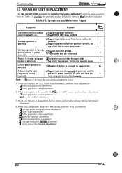
... Data sent by replaang the unit and adiusting the printer when necessary. When you disassemble the printer mechanism, perform these adjustments: Cl Bidirectional printing adjustment Q Platen gap motor value adjustment 2. A Table 5-3. Cl Some of the dots are not printed. 3 Printing is normal, but the self-test is on. QWhen the LF button is pressed, no paper is...
... Data sent by replaang the unit and adiusting the printer when necessary. When you disassemble the printer mechanism, perform these adjustments: Cl Bidirectional printing adjustment Q Platen gap motor value adjustment 2. A Table 5-3. Cl Some of the dots are not printed. 3 Printing is normal, but the self-test is on. QWhen the LF button is pressed, no paper is...

Service Manual
Page 144
Four connectors on the connector junction board in the printer mechanism. A s-7 No 4 I Perform the bidirectional I + 17END NOTE 1: Check the followin connectors: 1. Yes fault corrected? I 4 v Check printhead cable continuity. START E Perform the self-test. CN6 (Cl 17 MAiI board) 2. Replace any bad part. Rev. Visually check printhead pins. DFX-5000+ Service Manual 3. Carriage operation is normal, but the self-testis printed incorrectly. Troubleshooting Are the connectors inserted securely?
Four connectors on the connector junction board in the printer mechanism. A s-7 No 4 I Perform the bidirectional I + 17END NOTE 1: Check the followin connectors: 1. Yes fault corrected? I 4 v Check printhead cable continuity. START E Perform the self-test. CN6 (Cl 17 MAiI board) 2. Replace any bad part. Rev. Visually check printhead pins. DFX-5000+ Service Manual 3. Carriage operation is normal, but the self-testis printed incorrectly. Troubleshooting Are the connectors inserted securely?

Service Manual
Page 147
...5000+ Servke Manual Yes ; I Yes * (-., ..- 7 END J+ * Refer to Section 5.5, Repair of the PF motor coils and check the PF motor drivers. xEND K7END Refer to Chapter 4 and perform the PG motor backlash adjustment. 5-1o Rev. ~ drivers shorted or (.$":-i) ";L ' Perform final printing of self-test. Perform final printing of self-test. Is the No print... OK? ~ Refer to Section 5.5, Repair eof the Printer Mechanism. oIs the No print OK? Printing is normal, but ...
...5000+ Servke Manual Yes ; I Yes * (-., ..- 7 END J+ * Refer to Section 5.5, Repair of the PF motor coils and check the PF motor drivers. xEND K7END Refer to Chapter 4 and perform the PG motor backlash adjustment. 5-1o Rev. ~ drivers shorted or (.$":-i) ";L ' Perform final printing of self-test. Perform final printing of self-test. Is the No print... OK? ~ Refer to Section 5.5, Repair eof the Printer Mechanism. oIs the No print OK? Printing is normal, but ...

Service Manual
Page 149
Data sent by the host cmnputeris printed incorrectly. I Run the self-test. A Ttvubleshooting DEWiXXl+ Servke Manual 6. Built-in Parallel Check the cable connection from the host computer. Note: The flowchart below assumes the host computer is the ... No b v Replace Cl 17 MAIN board. No Set switches correctly. Replace Cl 17 MAIN board. j ".~-, optional IF for a network, is operating normally. [ START ) I No Troubleshoot printer using the previous flowcharts.
Data sent by the host cmnputeris printed incorrectly. I Run the self-test. A Ttvubleshooting DEWiXXl+ Servke Manual 6. Built-in Parallel Check the cable connection from the host computer. Note: The flowchart below assumes the host computer is the ... No b v Replace Cl 17 MAIN board. No Set switches correctly. Replace Cl 17 MAIN board. j ".~-, optional IF for a network, is operating normally. [ START ) I No Troubleshoot printer using the previous flowcharts.
Service Manual
Page 160
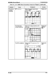
Observe the voltage waveform at pin 15 of IC7. Observe the PTS signal at the drain side. Checkpoint Observe the output signal at pins 129-137 of the CPU. The head driver FETs are defective. The CPU is printed incorrectly. F\ + ++++ 5V 1 Rev. C117 MAIN Board Assembly Component Repair (continued) Symptom The self-test is defective. Cause IC7 is defective. BVI Uv Replace the abnormal FET. DFX-5000+ Service Manual Troubleshooting Table 5-6. A S-23 LIVH j2QV AT. Solution Replace IC7. l,92ms SAVE Replace the CPU.
Observe the voltage waveform at pin 15 of IC7. Observe the PTS signal at the drain side. Checkpoint Observe the output signal at pins 129-137 of the CPU. The head driver FETs are defective. The CPU is printed incorrectly. F\ + ++++ 5V 1 Rev. C117 MAIN Board Assembly Component Repair (continued) Symptom The self-test is defective. Cause IC7 is defective. BVI Uv Replace the abnormal FET. DFX-5000+ Service Manual Troubleshooting Table 5-6. A S-23 LIVH j2QV AT. Solution Replace IC7. l,92ms SAVE Replace the CPU.


