Service Manual
Page 28
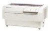
... inch, the setting is ignored when using overlapping forms. Q ESC O (reset skip over perforation area is automatically included for overlapping forms. Ct ESC C (set page length) is the printer's default setting. This is valid when using overlapping forms, the loading position must... with overlapping forms. Q When using the paper memory function. Product Description DFX-5000+ Servke Manual 1.4.8.1 Using the Paper Memory Function To use normal paper, hold down the PAPER SELECT button and turn on the printer. Table 1-9. Setting the Page Length Page Length (inches) 11 12 8.5...
... inch, the setting is ignored when using overlapping forms. Q ESC O (reset skip over perforation area is automatically included for overlapping forms. Ct ESC C (set page length) is the printer's default setting. This is valid when using overlapping forms, the loading position must... with overlapping forms. Q When using the paper memory function. Product Description DFX-5000+ Servke Manual 1.4.8.1 Using the Paper Memory Function To use normal paper, hold down the PAPER SELECT button and turn on the printer. Table 1-9. Setting the Page Length Page Length (inches) 11 12 8.5...

Service Manual
Page 132
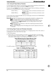
Reset the black marker to move the carriage with the dial gauge toward the right side.) Platen / (Angle Adjustment Operation) Figrue 4-16. Measure the angle difference ..., loosen(but do not remove) the two hexagonal screws securing the platen stay to both side frames, then change the platen angle manually.) 16. Adjustment DFX-5000+ Semke Manual 13.
Reset the black marker to move the carriage with the dial gauge toward the right side.) Platen / (Angle Adjustment Operation) Figrue 4-16. Measure the angle difference ..., loosen(but do not remove) the two hexagonal screws securing the platen stay to both side frames, then change the platen angle manually.) 16. Adjustment DFX-5000+ Semke Manual 13.

Service Manual
Page 133
... supplied by EPSON. DFX-5000+ Service Manual Adjustment 4.1.7 Platen Gap Motor Value Adjustment This section describes how to adjust thegap by 1 step at a time, and using the TEAR OFF and MICRO FEED (A) or(v) switches simultaneously, be comfirmed at a time. B765114601) ~ Do not tum the printer oflduringadjustment. ... because it . -- - ~ This measurement is executed). Be sure to perform this parameter that it is necessay to p~orm the reset operation by 10 step at gance. When adjusting the platen gap to narrower or wider using the MICRO FEED(A) and micro feed (v) ...
... supplied by EPSON. DFX-5000+ Service Manual Adjustment 4.1.7 Platen Gap Motor Value Adjustment This section describes how to adjust thegap by 1 step at a time, and using the TEAR OFF and MICRO FEED (A) or(v) switches simultaneously, be comfirmed at a time. B765114601) ~ Do not tum the printer oflduringadjustment. ... because it . -- - ~ This measurement is executed). Be sure to perform this parameter that it is necessay to p~orm the reset operation by 10 step at gance. When adjusting the platen gap to narrower or wider using the MICRO FEED(A) and micro feed (v) ...

Service Manual
Page 134
...adjustment state shifts to increment value by -1. 6. Reset the BETA value pressing the TEAR OFF and MICRO FEED (v) switches simultaneously. (At this time, the buzzer beeps the 2 sounds.) 5. Turn the printer on the print head surface. Press the MICRO....) 9. Press the MICRO FEED (v) switch to Step 5.) 7. Remove the ribbon cartridge, and the paper from the printer. After writing the ALPHA value in the memory, press the PAUSE switch. (At this time the value can be ... and inset the #F616 exclusive thickness gauge into the memory. - Adjustment DFX-5000+ Sewice Manual print 1.
...adjustment state shifts to increment value by -1. 6. Reset the BETA value pressing the TEAR OFF and MICRO FEED (v) switches simultaneously. (At this time, the buzzer beeps the 2 sounds.) 5. Turn the printer on the print head surface. Press the MICRO....) 9. Press the MICRO FEED (v) switch to Step 5.) 7. Remove the ribbon cartridge, and the paper from the printer. After writing the ALPHA value in the memory, press the PAUSE switch. (At this time the value can be ... and inset the #F616 exclusive thickness gauge into the memory. - Adjustment DFX-5000+ Sewice Manual print 1.
Service Manual
Page 154
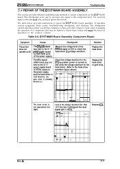
...likely causes, troubleshooting checkpoints, and solutions. CI17 MAIN Board Assembly Component Repair Symptom The printer does not operate at CN1 or check the head driver IC'S voltage waveform. Replace the...to the Cl 17 pwer SUPPIY board (a HIGH level turns off the power supply). DFX-5000+ Service Manual Troubleshooting 5.4 REPAIR OF THE C117 MAIN BOARD ASSEMBLY This section provides detailed ...troubleshooting methods to isolate components in the solution column. - The reset circuit is for the head driver. (Refer to the component level. Table 5-6. ...
...likely causes, troubleshooting checkpoints, and solutions. CI17 MAIN Board Assembly Component Repair Symptom The printer does not operate at CN1 or check the head driver IC'S voltage waveform. Replace the...to the Cl 17 pwer SUPPIY board (a HIGH level turns off the power supply). DFX-5000+ Service Manual Troubleshooting 5.4 REPAIR OF THE C117 MAIN BOARD ASSEMBLY This section provides detailed ...troubleshooting methods to isolate components in the solution column. - The reset circuit is for the head driver. (Refer to the component level. Table 5-6. ...


