
User Manual
Page 3
... from digital apparatus as set out in the instruction manual. These limits are cautioned that interference will not occur in a residential installation. However, there is required in order to meet FCC emission limits and also to prevent interference to provide reasonable protection against harmful interference in a particular installation. Use only shielded cables to connect I/O devices to which can radiate...
... from digital apparatus as set out in the instruction manual. These limits are cautioned that interference will not occur in a residential installation. However, there is required in order to meet FCC emission limits and also to prevent interference to provide reasonable protection against harmful interference in a particular installation. Use only shielded cables to connect I/O devices to which can radiate...

User Manual
Page 5
Contents Chapter 1 SYSTEM OVERVIEW 1 1-1 Introduction 2 Operating System 2 1-2 QuickStart 3 1-3 Features 4 1-4 Specifications 5 1-5 Example of a System Configuration 6 1-6 System Unit 7 1-7 Control Panel 8 Reset Button 8 Turbo Button 8 Indicator Lights 8 Keylock 9 System Power Switch 9 1-8 Rear Panel 1 1 Keyboard Connector 12 Power Cord Connector 13 Display Port 14 Power Voltage Setting 15 1-9 Other Peripherals 16 1-10 Disk Drives 17 Floppy Disks 18 Hard Disks 20 1-11 Keyboard 21 1-12 Maintaining Your Equipment 22 IV
Contents Chapter 1 SYSTEM OVERVIEW 1 1-1 Introduction 2 Operating System 2 1-2 QuickStart 3 1-3 Features 4 1-4 Specifications 5 1-5 Example of a System Configuration 6 1-6 System Unit 7 1-7 Control Panel 8 Reset Button 8 Turbo Button 8 Indicator Lights 8 Keylock 9 System Power Switch 9 1-8 Rear Panel 1 1 Keyboard Connector 12 Power Cord Connector 13 Display Port 14 Power Voltage Setting 15 1-9 Other Peripherals 16 1-10 Disk Drives 17 Floppy Disks 18 Hard Disks 20 1-11 Keyboard 21 1-12 Maintaining Your Equipment 22 IV

User Manual
Page 6
Chapter 2 SETTING UP YOUR SYSTEM 1 2-1 Motherboard 2 386SX CPU 3 Math Coprocessor 4 Chip Insertion 6 Jumpers 7 Onboard System Memory Size 8 ROM BIOS chips 18 2-2 Installation 19 2-3 Connection to Power Supply 20 Chapter 3 OPERATING YOUR SYSTEM 1 3-1 An lntroduction to DOS 2 Loading DOS 2 System Messages 2 3-2 DOS Operations 3 Starting MS-DOS 3 Formatting Disk 4 Backing up Your Diskettes and Files 5 Deleting Your Diskettes and Files 6 Finding Out What is on Your Disk 7 3-3 Hard Disk Drive Format 8 Step 1 - Partition 8 Step...
Chapter 2 SETTING UP YOUR SYSTEM 1 2-1 Motherboard 2 386SX CPU 3 Math Coprocessor 4 Chip Insertion 6 Jumpers 7 Onboard System Memory Size 8 ROM BIOS chips 18 2-2 Installation 19 2-3 Connection to Power Supply 20 Chapter 3 OPERATING YOUR SYSTEM 1 3-1 An lntroduction to DOS 2 Loading DOS 2 System Messages 2 3-2 DOS Operations 3 Starting MS-DOS 3 Formatting Disk 4 Backing up Your Diskettes and Files 5 Deleting Your Diskettes and Files 6 Finding Out What is on Your Disk 7 3-3 Hard Disk Drive Format 8 Step 1 - Partition 8 Step...

User Manual
Page 8
... Command Problems 2 5-2 System Error Messages 4 Examples of System Error Messages 5 5-3 System BIOS Error Messages 6 Chapter 6 APPENDIX 1 6-1 Disk Drives 2 5.25" Disk Drives 2 3.5" Disk Drives 7 6-2 Hard Disk Drive Format 9 Preformat 9 Partition 9 Format 9 6-3 Entering 16MHz Turbo Mode 10 Software Turbo Switch 10 Hardware Turbo Switch 10 Alternate Use of Both Switches 10 6-4 Software 11 Shadow RAM Enable 11 EMS Driver Setup 11 6-5 Quick Reference for Jumper Functions 14 6-6 Moving Your Computer and Peripherals 16 Short Move 16 Long Move 16 6-7 Technical Information 17...
... Command Problems 2 5-2 System Error Messages 4 Examples of System Error Messages 5 5-3 System BIOS Error Messages 6 Chapter 6 APPENDIX 1 6-1 Disk Drives 2 5.25" Disk Drives 2 3.5" Disk Drives 7 6-2 Hard Disk Drive Format 9 Preformat 9 Partition 9 Format 9 6-3 Entering 16MHz Turbo Mode 10 Software Turbo Switch 10 Hardware Turbo Switch 10 Alternate Use of Both Switches 10 6-4 Software 11 Shadow RAM Enable 11 EMS Driver Setup 11 6-5 Quick Reference for Jumper Functions 14 6-6 Moving Your Computer and Peripherals 16 Short Move 16 Long Move 16 6-7 Technical Information 17...

User Manual
Page 9
... 1-1: Quick Start 3 Figure 1-2: System Configuration 6 Figure 1-3: System Unit Case 7 Figure 1-4: Front Panel 8 Figure 1-5: Keylock and Two Security-Lock Keys 9 Figure 1-6: ON/OFF Switch (l/O Switch) in OFF Position 10 Figure 1-7: Rear Panel 11 Figure 1-8: Connecting the Keyboard Cable 12 Figure 1-9: System Power Cord 13 Figure 1-1 0: Two Kinds of Display Connectors 14 Figure 1-11: Voltage Switch 15 Figure 1-12: System Unit Connected to Peripherals 16 Figure 1-1 3: Installing Floppy and Hard Disk Drives 17 Figure...
... 1-1: Quick Start 3 Figure 1-2: System Configuration 6 Figure 1-3: System Unit Case 7 Figure 1-4: Front Panel 8 Figure 1-5: Keylock and Two Security-Lock Keys 9 Figure 1-6: ON/OFF Switch (l/O Switch) in OFF Position 10 Figure 1-7: Rear Panel 11 Figure 1-8: Connecting the Keyboard Cable 12 Figure 1-9: System Power Cord 13 Figure 1-1 0: Two Kinds of Display Connectors 14 Figure 1-11: Voltage Switch 15 Figure 1-12: System Unit Connected to Peripherals 16 Figure 1-1 3: Installing Floppy and Hard Disk Drives 17 Figure...

User Manual
Page 10
Figure 2-15: Installing ROM 18 Figure 2-16 : Unpacking your Main System 19 Figure 2-17: Connecting to a Power Supply 20 Chapter 3 OPERATING YOUR SYSTEM Figure 3-1: Initial Screen 13 Figure 3-2: "Set Up System Configuration" Screen 15 Figure 3-3: "Preformat Hard Disk" Screen 16 Figure 3-4: Calculator 17 Figure 3-5: "NEAT Chip Setup Configuration" Screen 18 Chapter 4 KEYBOARD Figure 4-1 : Keyboard Layout 2 Figure 4-2: Function Keys 3 Figure 4-3: Numeric Keypad 3 Figure 4-4: Indicator Lights 5 Figure 4-5: Special Keys 6 Figure 4-6: QWERTY Keys 7 Figure 4-7: Cursor Keys 8 Figure ...
Figure 2-15: Installing ROM 18 Figure 2-16 : Unpacking your Main System 19 Figure 2-17: Connecting to a Power Supply 20 Chapter 3 OPERATING YOUR SYSTEM Figure 3-1: Initial Screen 13 Figure 3-2: "Set Up System Configuration" Screen 15 Figure 3-3: "Preformat Hard Disk" Screen 16 Figure 3-4: Calculator 17 Figure 3-5: "NEAT Chip Setup Configuration" Screen 18 Chapter 4 KEYBOARD Figure 4-1 : Keyboard Layout 2 Figure 4-2: Function Keys 3 Figure 4-3: Numeric Keypad 3 Figure 4-4: Indicator Lights 5 Figure 4-5: Special Keys 6 Figure 4-6: QWERTY Keys 7 Figure 4-7: Cursor Keys 8 Figure ...
User Manual
Page 37
.... • Ensure that the power source is equipped with a 3-wire grounding-type plug. Refer all the instructions and warnings in this product yourself, as opening and removing covers exposes dangerous voltage areas and other risks. Do not use a damp cloth to service this manual and on these products! • Only use detergents! • Position your system unit, monitor and cables/wires away from direct sunlight, moisture, dust...
.... • Ensure that the power source is equipped with a 3-wire grounding-type plug. Refer all the instructions and warnings in this product yourself, as opening and removing covers exposes dangerous voltage areas and other risks. Do not use a damp cloth to service this manual and on these products! • Only use detergents! • Position your system unit, monitor and cables/wires away from direct sunlight, moisture, dust...

User Manual
Page 45
If a jumper needs to connect (short) two pins. Jumper Cap Top View I Pin 1 - Jumper Figure 2-4: An Example of a jumper. This has no effect on the function of switch which pins two and three are shorted. Jumper A jumper is a kind of the board while it keeps the cap handy. The illustration below shows the side and top views of a three-pin jumper in which uses a plastic cap with a metal interior to be left open, you should save the cap for future use by covering only one pin of Three-Pin Jumper Setting Chapter 2: Setting Up Your System 7 Side View -
If a jumper needs to connect (short) two pins. Jumper Cap Top View I Pin 1 - Jumper Figure 2-4: An Example of a jumper. This has no effect on the function of switch which pins two and three are shorted. Jumper A jumper is a kind of the board while it keeps the cap handy. The illustration below shows the side and top views of a three-pin jumper in which uses a plastic cap with a metal interior to be left open, you should save the cap for future use by covering only one pin of Three-Pin Jumper Setting Chapter 2: Setting Up Your System 7 Side View -
User Manual
Page 63
... message on the screen following the RAM test: Non-system disk or disk error Replace and strike any key when ready Then, you turn on system messages. 2 Chapter 3: Operating Your System System Messages Refer to your computer, you will boot automatically whenever you should follow the instructions below to reboot your hard disk: If you use applications and create and manage files on the monitor. You should : •...
... message on the screen following the RAM test: Non-system disk or disk error Replace and strike any key when ready Then, you turn on system messages. 2 Chapter 3: Operating Your System System Messages Refer to your computer, you will boot automatically whenever you should follow the instructions below to reboot your hard disk: If you use applications and create and manage files on the monitor. You should : •...

User Manual
Page 64
.... You will 'boot" or start itself. 3-2 DOS Operations Following is F r i 01-01-1990 Enter new date (MM-DD-YY): For the new date, key in drive "A" and switch on your DOS user manual. If you are using a floppy disk drive, insert the DOS system disk in the month, day and year, separated by hyphens. Starting MS-DOS If you are using a hard disk with DOS already installed, the computer will...
.... You will 'boot" or start itself. 3-2 DOS Operations Following is F r i 01-01-1990 Enter new date (MM-DD-YY): For the new date, key in drive "A" and switch on your DOS user manual. If you are using a floppy disk drive, insert the DOS system disk in the month, day and year, separated by hyphens. Starting MS-DOS If you are using a hard disk with DOS already installed, the computer will...
User Manual
Page 72
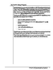
... disk format utility • three system utilities (a calculator, a hard disk park, and a timer) • system password • user-defined hard disk types • Neat chip set the date, time, base memory, expansion memory, number of floppy and hard disk drives and display configuration as well as get information on the motherboard. The following will guide you can set The setup program is simple to your BIOS on hard disk types. Specifically, you through the setup program. It is used . Chapter 3: Operating...
... disk format utility • three system utilities (a calculator, a hard disk park, and a timer) • system password • user-defined hard disk types • Neat chip set the date, time, base memory, expansion memory, number of floppy and hard disk drives and display configuration as well as get information on the motherboard. The following will guide you can set The setup program is simple to your BIOS on hard disk types. Specifically, you through the setup program. It is used . Chapter 3: Operating...

User Manual
Page 92
... air conditioner. This appliance is inexpensive and can be a big problem is with the + key combination. List the actions you run your MS-DOS manual for major surgery, check the following items. £ Make sure that your disks or disk drives? Is it with a certain software program or with the hardware, try to find out the conditions under which the malfunction...
... air conditioner. This appliance is inexpensive and can be a big problem is with the + key combination. List the actions you run your MS-DOS manual for major surgery, check the following items. £ Make sure that your disks or disk drives? Is it with a certain software program or with the hardware, try to find out the conditions under which the malfunction...

User Manual
Page 100
... the instructions below to the disk drive as shown below : • Open the system unit case as that may at sometime want to add to or exchange your floppy or hard disk drives. Be certain to refer to the manuals for both the disk drive and the controller card for any additional specific information regarding them that for a floppy disk. 6-1 Disk Drives Two 5.25" floppy/hard disk drives and two 3.5" floppy/hard disk drives...
... the instructions below to the disk drive as shown below : • Open the system unit case as that may at sometime want to add to or exchange your floppy or hard disk drives. Be certain to refer to the manuals for both the disk drive and the controller card for any additional specific information regarding them that for a floppy disk. 6-1 Disk Drives Two 5.25" floppy/hard disk drives and two 3.5" floppy/hard disk drives...

User Manual
Page 101
The power cable is simple to connect: simply plug it in to the disk drive bay as shown below: Figure 6-2: Screwing the 5.25" Disk Drives • Next, connect the floppy/hard disk controller cable and one of the plug ensures that no mistakes will be made. See the figures on the following pages. Chapter 6: Appendix 3 • Screw the disk drive to the correct adapter. The shape of the four cables from the power supply.
The power cable is simple to connect: simply plug it in to the disk drive bay as shown below: Figure 6-2: Screwing the 5.25" Disk Drives • Next, connect the floppy/hard disk controller cable and one of the plug ensures that no mistakes will be made. See the figures on the following pages. Chapter 6: Appendix 3 • Screw the disk drive to the correct adapter. The shape of the four cables from the power supply.

User Manual
Page 105
3.5"DiskDrive The installation of a 3.5" disk drive is similar to the chassis. e. • First fasten the bracket on the drive. • Next, place the disk drive inside the bay and fasten the brackets to that for a 5.25" disk dddrirveiv. Refer to the figure below: Figure 6-8: Installing a 3.5" Disk Drive Chapter 6: Appendix 7
3.5"DiskDrive The installation of a 3.5" disk drive is similar to the chassis. e. • First fasten the bracket on the drive. • Next, place the disk drive inside the bay and fasten the brackets to that for a 5.25" disk dddrirveiv. Refer to the figure below: Figure 6-8: Installing a 3.5" Disk Drive Chapter 6: Appendix 7

User Manual
Page 108
... Switches Both the hardware and the software switches may be used alternatively, but this is connected to a closed hardware Turbo switch, the speed can be on the Turbo LED, refer to toggle between Turbo and Normal from the keyboard. Hardware Turbo Switch If your hardware Turbo switch is its dual clock system. The two switches are set up the board yourself. Alternate Use of operation. Entering 16MHz Turbo Mode The PPM-1630C supports both switches...
... Switches Both the hardware and the software switches may be used alternatively, but this is connected to a closed hardware Turbo switch, the speed can be on the Turbo LED, refer to toggle between Turbo and Normal from the keyboard. Hardware Turbo Switch If your hardware Turbo switch is its dual clock system. The two switches are set up the board yourself. Alternate Use of operation. Entering 16MHz Turbo Mode The PPM-1630C supports both switches...
User Manual
Page 109
... efficient execution of BIOS, it is always allocated at the same address for BIOS and video. l Select item 6 to enter setup menu, too. To enable shadow RAM, follow the steps below : l Hold down the key to run BIOS code through RAM rather than one megabyte memory, you turn the power on . The 384K is preferable to enter the DTK BIOS setup menu as you may reset the system to enter NEAT Chip Setup Configuration.
... efficient execution of BIOS, it is always allocated at the same address for BIOS and video. l Select item 6 to enter setup menu, too. To enable shadow RAM, follow the steps below : l Hold down the key to run BIOS code through RAM rather than one megabyte memory, you turn the power on . The 384K is preferable to enter the DTK BIOS setup menu as you may reset the system to enter NEAT Chip Setup Configuration.

User Manual
Page 114
... while the computer is being moved. • Turn off all power switches. • Insert the cardboard diskette/s supplied with the system unit into the disk drive/s and close the disk drive levers. • Detach all items in their original packing cases. 16 Chapter 6: Appendix This command will lock up onto floppy disks. • Enter the DOS system program and invoke the PARK...
... while the computer is being moved. • Turn off all power switches. • Insert the cardboard diskette/s supplied with the system unit into the disk drive/s and close the disk drive levers. • Detach all items in their original packing cases. 16 Chapter 6: Appendix This command will lock up onto floppy disks. • Enter the DOS system program and invoke the PARK...

User Manual
Page 124
.... add-on a printed circuit board for Information Interchange. A type of information vehicle whereby data can be transmitted at any time without requiring synchronized timing. Otherwise, there will come across frequently in this is usually divided into rows. This card connects through expansion slots to specific memory locations so that devices do not have the same address. Also known as an adapter...
.... add-on a printed circuit board for Information Interchange. A type of information vehicle whereby data can be transmitted at any time without requiring synchronized timing. Otherwise, there will come across frequently in this is usually divided into rows. This card connects through expansion slots to specific memory locations so that devices do not have the same address. Also known as an adapter...

User Manual
Page 130
...-speed virtual disk - Also referred to ensure the long life and troublefree operation of the memory chips are pauses. This is a standardized communications interface between devices. setup - Syncopated transmission of memory used to be viewed, altered or stored. Turbo - Read Only Memory. Chapter 7: Glossary 7 Although this section carefully. window - RS-232 - RS232 is data that can be invoked onto the monitor...
...-speed virtual disk - Also referred to ensure the long life and troublefree operation of the memory chips are pauses. This is a standardized communications interface between devices. setup - Syncopated transmission of memory used to be viewed, altered or stored. Turbo - Read Only Memory. Chapter 7: Glossary 7 Although this section carefully. window - RS-232 - RS232 is data that can be invoked onto the monitor...


