Service Manual
Page 6
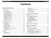
EPSON Stylus Pro 4000 Contents Revision B Chapter 1 Product Description 1.1 Product Description 10 1.1.1 Features 10 1.2 Basic Specifications 12 1.2.1 Print Specifications 12 1.2.2 Character ... Consumables 113 1.7.1 Ink Cartridge 113 1.7.2 Cleaning cartridge 114 1.7.3 Maintenance Tank 114 Chapter 2 Operating Principles 2.1 Overview 116 2.2 Printer Mechanism Components 117 2.2.1 Printing Mechanism (Print Head 118 2.2.2 Ink Supply Mechanism 119 2.2.3 Cleaning Mechanism 121 2.2.4 Carriage (CR) Mechanism 126 2.2.5 Paper Feed Mechanism 132 2.2.6 Paper Eject/Release Mechanism...
EPSON Stylus Pro 4000 Contents Revision B Chapter 1 Product Description 1.1 Product Description 10 1.1.1 Features 10 1.2 Basic Specifications 12 1.2.1 Print Specifications 12 1.2.2 Character ... Consumables 113 1.7.1 Ink Cartridge 113 1.7.2 Cleaning cartridge 114 1.7.3 Maintenance Tank 114 Chapter 2 Operating Principles 2.1 Overview 116 2.2 Printer Mechanism Components 117 2.2.1 Printing Mechanism (Print Head 118 2.2.2 Ink Supply Mechanism 119 2.2.3 Cleaning Mechanism 121 2.2.4 Carriage (CR) Mechanism 126 2.2.5 Paper Feed Mechanism 132 2.2.6 Paper Eject/Release Mechanism...

Service Manual
Page 57
EPSON Stylus Pro 4000 1.4.4.20 Job Information Print With this mode, users can print job ... † Print sample : Refer to "1.4.3 Job information (p36)". Job No. 7 : Doc Name : Status Sheet User Name: Printer I /F Type : Not Used Job State : Supplies : Ink : 0.203 ml Paper (WxH) : 609 mm x 179 mm Print start time : 02/05/02 10:29 Used...Print start time : 02/05/02 12:54 Used Time : 1 min. Job No. 4 : Doc Name : Status Sheet User Name: Printer I /F Type : Parallel Job State : Supplies : Ink : 0.236 ml Paper (WxH) : 610 mm x 319 mm Print start time : 02/05/02 12:31 Used Time ...
EPSON Stylus Pro 4000 1.4.4.20 Job Information Print With this mode, users can print job ... † Print sample : Refer to "1.4.3 Job information (p36)". Job No. 7 : Doc Name : Status Sheet User Name: Printer I /F Type : Not Used Job State : Supplies : Ink : 0.203 ml Paper (WxH) : 609 mm x 179 mm Print start time : 02/05/02 10:29 Used...Print start time : 02/05/02 12:54 Used Time : 1 min. Job No. 4 : Doc Name : Status Sheet User Name: Printer I /F Type : Parallel Job State : Supplies : Ink : 0.236 ml Paper (WxH) : 610 mm x 319 mm Print start time : 02/05/02 12:31 Used Time ...

Service Manual
Page 62
... Description Operating Panel 62 Therefore it is calculated by accumulation of CR to and fro, so it is severely impacted by abrasion and failure of supply tube. Supply tube life is defined by amount of to and fro times. (Reference value: 260 million Pass) „ Display (Life) 100 ~ 81% ... occur to the status of user usage, this value should be the correct value. EPSON Stylus Pro 4000 1.4.4.31 Consumable Life † Cutter life „ Calculate method Counter that is calculated by accumulating total of cutter used as supply tube life (for A2 width) and is indicated by...
... Description Operating Panel 62 Therefore it is calculated by accumulation of CR to and fro, so it is severely impacted by abrasion and failure of supply tube. Supply tube life is defined by amount of to and fro times. (Reference value: 260 million Pass) „ Display (Life) 100 ~ 81% ... occur to the status of user usage, this value should be the correct value. EPSON Stylus Pro 4000 1.4.4.31 Consumable Life † Cutter life „ Calculate method Counter that is calculated by accumulating total of cutter used as supply tube life (for A2 width) and is indicated by...

Service Manual
Page 116
The explanation is composed as follows: † 2.2 Printer Mechanism Components (p.117) „ 2.2.1 Printing Mechanism (Print Head) (p.118) „ 2.2.2 Ink Supply Mechanism (p.119) „ 2.2.4 Carriage (CR) Mechanism (p.126) „ 2.2.5 Paper Feed Mechanism (p.132) „ 2.2.6...; 2.2.8 Others (p.152) † 2.3 Outline of Control Circuit Board (p.153) † 2.4 Outline of Power Supply Circuit Board (p.154) Revision B Operating Principles Overview 116 EPSON Stylus Pro 4000 2.1 Overview This chapter explains the printer mechanism and operating principles for the EPSON Stylus Pro 4000.
The explanation is composed as follows: † 2.2 Printer Mechanism Components (p.117) „ 2.2.1 Printing Mechanism (Print Head) (p.118) „ 2.2.2 Ink Supply Mechanism (p.119) „ 2.2.4 Carriage (CR) Mechanism (p.126) „ 2.2.5 Paper Feed Mechanism (p.132) „ 2.2.6...; 2.2.8 Others (p.152) † 2.3 Outline of Control Circuit Board (p.153) † 2.4 Outline of Power Supply Circuit Board (p.154) Revision B Operating Principles Overview 116 EPSON Stylus Pro 4000 2.1 Overview This chapter explains the printer mechanism and operating principles for the EPSON Stylus Pro 4000.

Service Manual
Page 117
...x 8 rows p.118 Head Thermistor +3.3V Incorporated in the Printer Mechanism of this printer are as shown below. Printer control/drive circuit board p.153 Power Supply Board - Printer Mechanism Components Part Drive voltage Description Reference P_THICK Sensor (Paper .../ pressure lever) p.134 Revision B Table 2-1. Power supply PCB p.154 Operating Principles Printer Mechanism Components 117 Hereafter, we will explain each Printer Mechanism focusing on these parts. EPSON Stylus Pro 4000 2.2 Printer Mechanism Components The major electrical parts used in the Print...
...x 8 rows p.118 Head Thermistor +3.3V Incorporated in the Printer Mechanism of this printer are as shown below. Printer control/drive circuit board p.153 Power Supply Board - Printer Mechanism Components Part Drive voltage Description Reference P_THICK Sensor (Paper .../ pressure lever) p.134 Revision B Table 2-1. Power supply PCB p.154 Operating Principles Printer Mechanism Components 117 Hereafter, we will explain each Printer Mechanism focusing on these parts. EPSON Stylus Pro 4000 2.2 Printer Mechanism Components The major electrical parts used in the Print...

Service Manual
Page 119
... quantity is stored in the EEPROM on the C511 Main Board. EPSON Stylus Pro 4000 2.2.2 Ink Supply Mechanism This printer has ink cartridges for each color ink cartridge passes through the CSIC relay circuit board on each color ink cartridge to "Ink Information Menu" (p.77).) Operating Principles Printer Mechanism Components 119 Valve Mechanism To Print Head Ink Cartridge Ink...
... quantity is stored in the EEPROM on the C511 Main Board. EPSON Stylus Pro 4000 2.2.2 Ink Supply Mechanism This printer has ink cartridges for each color ink cartridge passes through the CSIC relay circuit board on each color ink cartridge to "Ink Information Menu" (p.77).) Operating Principles Printer Mechanism Components 119 Valve Mechanism To Print Head Ink Cartridge Ink...

Service Manual
Page 120
...each have 1 I /H Lever Sensor (Right) 2 3 4 5 Figure 2-4. I/H Lever Sensor (Left) I /H Lever Sensor located on the side. Ink Route inside of Dumper (1) Figure 2-6. EPSON Stylus Pro 4000 † Dumper The dumper is equipped with a valve to the Print Head. I/H Lever Sensor Valve Close Valve Open Figure 2-5. Ink Route inside the ink storage... the ink lever. This sensor uses a reverse tension switch (mechanical contact) to detect whether the ink cartridge is supplied to prevent reverse flow of ink, and when this valve opens the ink inside of Dumper (2) Operating Principles...
...each have 1 I /H Lever Sensor (Right) 2 3 4 5 Figure 2-4. I/H Lever Sensor (Left) I /H Lever Sensor located on the side. Ink Route inside of Dumper (1) Figure 2-6. EPSON Stylus Pro 4000 † Dumper The dumper is equipped with a valve to the Print Head. I/H Lever Sensor Valve Close Valve Open Figure 2-5. Ink Route inside the ink storage... the ink lever. This sensor uses a reverse tension switch (mechanical contact) to detect whether the ink cartridge is supplied to prevent reverse flow of ink, and when this valve opens the ink inside of Dumper (2) Operating Principles...

Service Manual
Page 152
... side to detect the removed/ installed condition of the Printer Cover. Cover Sensor/Panel Unit AC Inlet Operating Principles Power Supply Circuit Board Figure 2-61. EPSON Stylus Pro 4000 2.2.8 Others P-COVER OPEN SENSOR This sensor is mounted to the printer front right surface, and an AC Inlet, Power Supply Circuit Board and MAIN Circuit Board are mounted in...
... side to detect the removed/ installed condition of the Printer Cover. Cover Sensor/Panel Unit AC Inlet Operating Principles Power Supply Circuit Board Figure 2-61. EPSON Stylus Pro 4000 2.2.8 Others P-COVER OPEN SENSOR This sensor is mounted to the printer front right surface, and an AC Inlet, Power Supply Circuit Board and MAIN Circuit Board are mounted in...

Service Manual
Page 153
...• USB-I /F control Revision B Model No. C511 MAIN Board - EPSON Stylus Pro 4000 2.3 Outline of Control Circuit Board This section describes the operation of C511 MAIN Board, which controls and drives the Printer Mechanism of various setting parameters and control information IC10 32bit RISC-CPU • ...year/month/day by F/W • MAIN PCB reset signal formation IC21 Custom ASICC 1. Major Elements Location Function IC1 3 terminal regulator • Supply voltage (5V) from the Power PCB is stepped down to "Chapter 7: Appendix (p.431) at the end of this volume. † ...
...• USB-I /F control Revision B Model No. C511 MAIN Board - EPSON Stylus Pro 4000 2.3 Outline of Control Circuit Board This section describes the operation of C511 MAIN Board, which controls and drives the Printer Mechanism of various setting parameters and control information IC10 32bit RISC-CPU • ...year/month/day by F/W • MAIN PCB reset signal formation IC21 Custom ASICC 1. Major Elements Location Function IC1 3 terminal regulator • Supply voltage (5V) from the Power PCB is stepped down to "Chapter 7: Appendix (p.431) at the end of this volume. † ...

Service Manual
Page 154
... becomes active. There are active. EPSON Stylus Pro 4000 Revision B 2.4 Outline of Power Supply Circuit Board 154 Operating Principles Outline of Power Supply Circuit Board 100VAC from the Power Supply Circuit Board has become inactive because of turning off , the Power Supply Circuit Board does not stop operating ...shorted, the drive system power supplies 28 VDC and 42 VDC are three control signals between the C511 MAIN Board and the Power Supply Circuit Board. OFF (=L) The power switch is supplied to the power switch on the printer. The secondary power switch ...
... becomes active. There are active. EPSON Stylus Pro 4000 Revision B 2.4 Outline of Power Supply Circuit Board 154 Operating Principles Outline of Power Supply Circuit Board 100VAC from the Power Supply Circuit Board has become inactive because of turning off , the Power Supply Circuit Board does not stop operating ...shorted, the drive system power supplies 28 VDC and 42 VDC are three control signals between the C511 MAIN Board and the Power Supply Circuit Board. OFF (=L) The power switch is supplied to the power switch on the printer. The secondary power switch ...
Service Manual
Page 167
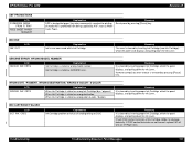
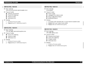
...Ink Cartridge (dye / pigment). When Ink Cartridge is stated as wrong destination. When Ink Cartridge is stated as wrong color (4-color / 8-color). EPSON Stylus Pro 4000 Revision B ASF PROHIBITIONS LCD FORBIDDEN MEDIA FROM P. Recovery Reset panel by inserting proper Ink Cartridge, which the panel displays,... ASF, such as GENUINE error. Troubleshooting Troubleshooting Based on Panel Messages 167 Recovery The error is prohibited from being supplied by inserting proper Ink Cartridge, which the panel LCD displays and pulling down the Ink Lever. If CSIC contact ...
...Ink Cartridge (dye / pigment). When Ink Cartridge is stated as wrong destination. When Ink Cartridge is stated as wrong color (4-color / 8-color). EPSON Stylus Pro 4000 Revision B ASF PROHIBITIONS LCD FORBIDDEN MEDIA FROM P. Recovery Reset panel by inserting proper Ink Cartridge, which the panel displays,... ASF, such as GENUINE error. Troubleshooting Troubleshooting Based on Panel Messages 167 Recovery The error is prohibited from being supplied by inserting proper Ink Cartridge, which the panel LCD displays and pulling down the Ink Lever. If CSIC contact ...

Service Manual
Page 169
... period will be caused by back feeding, a message is displayed on Panel Messages 169 EPSON Stylus Pro 4000 RELEASING PAPER LEVER LCD LOAD PAPER (Except roll paper) LOAD PAPER SUCTION (Roll paper .... † When only the PE Sensor turns ON with the Paper Lever lowered, front paper supply is stopped. In this case, release the Paper Lever again and remove the paper, and then...turns ON at paper feed/print/eject movements of the movements. Troubleshooting Troubleshooting Based on the printer about removing paper and operation is determined by the paper set sequence is resumed by paper...
... period will be caused by back feeding, a message is displayed on Panel Messages 169 EPSON Stylus Pro 4000 RELEASING PAPER LEVER LCD LOAD PAPER (Except roll paper) LOAD PAPER SUCTION (Roll paper .... † When only the PE Sensor turns ON with the Paper Lever lowered, front paper supply is stopped. In this case, release the Paper Lever again and remove the paper, and then...turns ON at paper feed/print/eject movements of the movements. Troubleshooting Troubleshooting Based on the printer about removing paper and operation is determined by the paper set sequence is resumed by paper...
Service Manual
Page 190
...; Cause of trouble „ Defective circuit board „ Faulty CPU soldering „ Program trouble „ Generation error † Remedy 1. Replace the Power Supply Board (p228) 3. Installing Firmware (p424) 2. EPSON Stylus Pro 4000 SERVICE REQ. 10000180 † Error meaning: CPU reserve command code exception error † Cause of trouble „ Power outage „ Unplugged from electric...
...; Cause of trouble „ Defective circuit board „ Faulty CPU soldering „ Program trouble „ Generation error † Remedy 1. Replace the Power Supply Board (p228) 3. Installing Firmware (p424) 2. EPSON Stylus Pro 4000 SERVICE REQ. 10000180 † Error meaning: CPU reserve command code exception error † Cause of trouble „ Power outage „ Unplugged from electric...

Service Manual
Page 197
...to observe the following disassembly/reassembly are stopped by the cover sensor when the "Cover, Printer" or "Paper Guide, Inner Unit" is always supplied unless the power cord has been unplugged. Be sure to the appendix Exploded Diagrams (p.442... POINT" symbol. † REASSEMBLY Reassembly steps that differ from reverse procedures for the Stylus Pro 4000. Refer to "Chapter 5: Adjustments" and be sure to perform the specified adjustments. EPSON Stylus Pro 4000 Revision B 4.1 Introductory Information This chapter describes disassembly/reassembly steps for disassembly steps are ...
...to observe the following disassembly/reassembly are stopped by the cover sensor when the "Cover, Printer" or "Paper Guide, Inner Unit" is always supplied unless the power cord has been unplugged. Be sure to the appendix Exploded Diagrams (p.442... POINT" symbol. † REASSEMBLY Reassembly steps that differ from reverse procedures for the Stylus Pro 4000. Refer to "Chapter 5: Adjustments" and be sure to perform the specified adjustments. EPSON Stylus Pro 4000 Revision B 4.1 Introductory Information This chapter describes disassembly/reassembly steps for disassembly steps are ...

Service Manual
Page 221
..." notch and remove the "Cover, Harness". (Refer to Figure 4-31.) Do not allow any harness to circuit board components.) 1. EPSON Stylus Pro 4000 4.2.4 Circuit Board Removal This section describes steps for removing "C511 MAIN Board", "Power Supply Board", and each "C511_SUB Board". 4.2.4.1 C511 MAIN Board C A U T IO N Be sure to insert and unplug FFCs vertically. (Inserting...
..." notch and remove the "Cover, Harness". (Refer to Figure 4-31.) Do not allow any harness to circuit board components.) 1. EPSON Stylus Pro 4000 4.2.4 Circuit Board Removal This section describes steps for removing "C511 MAIN Board", "Power Supply Board", and each "C511_SUB Board". 4.2.4.1 C511 MAIN Board C A U T IO N Be sure to insert and unplug FFCs vertically. (Inserting...

Service Manual
Page 223
EPSON Stylus Pro 4000 7. Connectors/Harnesses Connected to disconnect FFC. Disconnect all connectors/harnesses from... CN14 CN8 CN1 CN50 Figure 4-33. Table 4-3. Revision B CHECK P O IN T Release the harness lock as shown in Table 4-3. Color Number of Pins Connection Socket 1 CN48 - 17 C511_SUB-B Board (CN102) 2 CN51 - 30 C511_SUB-B Board (CN101) 3 CN54 - ...Rear Cover Sensor 14 CN15 White 3 CR Motor 15 CN14 Black 3 PF Motor 16 CN1 White 14 Power Supply Board (CN2) 17 CN50 White 2 Heat Dissipation Plate Cooling Fan Note 1: CN3, C21, CN23, CN47 ...
EPSON Stylus Pro 4000 7. Connectors/Harnesses Connected to disconnect FFC. Disconnect all connectors/harnesses from... CN14 CN8 CN1 CN50 Figure 4-33. Table 4-3. Revision B CHECK P O IN T Release the harness lock as shown in Table 4-3. Color Number of Pins Connection Socket 1 CN48 - 17 C511_SUB-B Board (CN102) 2 CN51 - 30 C511_SUB-B Board (CN101) 3 CN54 - ...Rear Cover Sensor 14 CN15 White 3 CR Motor 15 CN14 Black 3 PF Motor 16 CN1 White 14 Power Supply Board (CN2) 17 CN50 White 2 Heat Dissipation Plate Cooling Fan Note 1: CN3, C21, CN23, CN47 ...

Service Manual
Page 227
EPSON Stylus Pro 4000 13. Do not place the circuit board (solder side) directly on a conductive surface. „ Circuit boards supplied as keeping IEEE1394 connector clear of the plate. A D JU S TM E N T R E Q U IR E D Be sure to refer to Chapter 5 "Adjustment" (p.354) and perform specified adjustments after replacing ...
EPSON Stylus Pro 4000 13. Do not place the circuit board (solder side) directly on a conductive surface. „ Circuit boards supplied as keeping IEEE1394 connector clear of the plate. A D JU S TM E N T R E Q U IR E D Be sure to refer to Chapter 5 "Adjustment" (p.354) and perform specified adjustments after replacing ...
Service Manual
Page 228
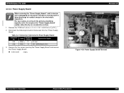
EPSON Stylus Pro 4000 4.2.4.2 Power Supply Board W A R N IN G When removing the "Power Supply Board", wait 5 minutes after unplugging the AC power cord before starting work to allow discharge of Pins Connection Socket CN1 White 2 AC Inlet CN2 White 14 C511 MAIN Board (CN1) 3. Do not place the "Power Supply Board" (solder side) directly on a conductive surface. 1. Table 4-4. Connectors...
EPSON Stylus Pro 4000 4.2.4.2 Power Supply Board W A R N IN G When removing the "Power Supply Board", wait 5 minutes after unplugging the AC power cord before starting work to allow discharge of Pins Connection Socket CN1 White 2 AC Inlet CN2 White 14 C511 MAIN Board (CN1) 3. Do not place the "Power Supply Board" (solder side) directly on a conductive surface. 1. Table 4-4. Connectors...

Service Manual
Page 235
... using highly precise adjustments. Therefore removal or replacement of the printer mechanism. Revision B Disassembly & Assembly Disassembly Procedures 235 EPSON Stylus Pro 4000 4.2.5 Printer Mechanism Disassembly This section describes disassembly steps for main components of parts that cannot be supplied as components defined in this manual or parts supplied as "Service Parts" is prohibited. (If this is required on...
... using highly precise adjustments. Therefore removal or replacement of the printer mechanism. Revision B Disassembly & Assembly Disassembly Procedures 235 EPSON Stylus Pro 4000 4.2.5 Printer Mechanism Disassembly This section describes disassembly steps for main components of parts that cannot be supplied as components defined in this manual or parts supplied as "Service Parts" is prohibited. (If this is required on...

Service Manual
Page 281
... to bend the "Tube, Supply, Ink". C.P.P. 2.6x8 Figure 4-108. Carriage Unit Setting / Screws Securing Carriage, C Disassembly & Assembly Disassembly Procedures 281 If it get bend, replace with its bottom is installed to Figure 4-108.) „ C.C.P. 2.6 x 8 : 3 pcs. Attach the "CUTTER CAP" to the cutter section of the "Carriage Unit". EPSON Stylus Pro 4000 8. Set the "Carriage Unit...
... to bend the "Tube, Supply, Ink". C.P.P. 2.6x8 Figure 4-108. Carriage Unit Setting / Screws Securing Carriage, C Disassembly & Assembly Disassembly Procedures 281 If it get bend, replace with its bottom is installed to Figure 4-108.) „ C.C.P. 2.6 x 8 : 3 pcs. Attach the "CUTTER CAP" to the cutter section of the "Carriage Unit". EPSON Stylus Pro 4000 8. Set the "Carriage Unit...


