Service Manual
Page 192
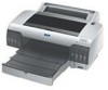
EPSON Stylus Pro 4000 Revision B 3.3 Troubleshooting Based on Your Printout This section describes conceivable print quality problems that may occur with a new one of the following points. „ If trouble occurs in all the ink colors...ink is dirty. • Abnormal connections between the Ink Cartridge, Ink Holder, Tube, Damper, Print Head. (Fastening nuts loose, or the O-ring deformed or damaged, causing ink ... p.193 p.193 p.194 p.194 p.195 DOT MISSING Auto cleaning is OFF or printer has not been used for those errors. Cleaning Cleaning Power cleaning Initial ink charge Execution...
EPSON Stylus Pro 4000 Revision B 3.3 Troubleshooting Based on Your Printout This section describes conceivable print quality problems that may occur with a new one of the following points. „ If trouble occurs in all the ink colors...ink is dirty. • Abnormal connections between the Ink Cartridge, Ink Holder, Tube, Damper, Print Head. (Fastening nuts loose, or the O-ring deformed or damaged, causing ink ... p.193 p.193 p.194 p.194 p.195 DOT MISSING Auto cleaning is OFF or printer has not been used for those errors. Cleaning Cleaning Power cleaning Initial ink charge Execution...

Service Manual
Page 286
...", to Chapter 5 "Adjustment" (p.354) and perform specified adjustments after replacing or removing the "Valve Assy., Head". "Plate, Damper" Drawing Joint Section Tab 1 2 1 Valve Assy., Head Film Area (both sides) Disassembly & Assembly Figure 4-115. Release ...Damper" with a plier or a similar tool. (Refer to Figure 4-114.) C A U T IO N When performing the following the steps below. (Refer to "4.2.7.1 Carriage Unit" (p260).) 4. Separate the "Carriage, C" from the "Carriage Unit". (Refer to Figure 4-115.) 6-1. Revision B Plate, Damper Figure 4-114. EPSON Stylus Pro 4000 ...
...", to Chapter 5 "Adjustment" (p.354) and perform specified adjustments after replacing or removing the "Valve Assy., Head". "Plate, Damper" Drawing Joint Section Tab 1 2 1 Valve Assy., Head Film Area (both sides) Disassembly & Assembly Figure 4-115. Release ...Damper" with a plier or a similar tool. (Refer to Figure 4-114.) C A U T IO N When performing the following the steps below. (Refer to "4.2.7.1 Carriage Unit" (p260).) 4. Separate the "Carriage, C" from the "Carriage Unit". (Refer to Figure 4-115.) 6-1. Revision B Plate, Damper Figure 4-114. EPSON Stylus Pro 4000 ...
Service Manual
Page 355
EPSON Stylus Pro 4000 Revision B 5.1 Overview This section describes the adjustment procedures necessary after being replaced or removed are performed improperly. 5.1.2 Advance of each adjustment item. Table 5-1. The...that is required Adjustment Repair Items (Disassembly/Reassembly Reference Page) Main Circuit Board*1 (C511 MAIN Board (p221)) Cleaning Unit*2 (p.309) Printhead (p278) Damper (Valve Assy., Head (p.284)) AS Mechanical Unit (Printer Mechanism (SP) (p.236)) ASF Unit (p.240) Motor Motor Assy., CR (p264) Motor Assy., PF (p341) Pump Motor (Mounting Plate Assy.,...
EPSON Stylus Pro 4000 Revision B 5.1 Overview This section describes the adjustment procedures necessary after being replaced or removed are performed improperly. 5.1.2 Advance of each adjustment item. Table 5-1. The...that is required Adjustment Repair Items (Disassembly/Reassembly Reference Page) Main Circuit Board*1 (C511 MAIN Board (p221)) Cleaning Unit*2 (p.309) Printhead (p278) Damper (Valve Assy., Head (p.284)) AS Mechanical Unit (Printer Mechanism (SP) (p.236)) ASF Unit (p.240) Motor Motor Assy., CR (p264) Motor Assy., PF (p341) Pump Motor (Mounting Plate Assy.,...

Service Manual
Page 357
EPSON Stylus Pro 4000 Table 5-2. P.382 13 Printhead Slant Adjustment (CR) { --- P.384 14 Auto Uni-d Adjustment { --- P.413 16 Manual Bi-D 17 Image Adjustment { { P.414 { { ...--- P.421 Paper Thickness 1 Paper Thickness Sensor Adjustment Sensor { { P.367 Multi Sensor 1 Multi Sensor Position Adjustment { { P.372 2 Multi Sensor Level Adjustment { { P.376 3 T&B&S (Roll Paper) { --- Damper 1 Ink Discharge { { P.397 2 CR Timing Belt Tension Adjustment { { P.363 3 CR Encoder Sensor Position Adjustment { { P.369 4 Initial Ink Charge { { P.398 5 Head Rank ID { --- P....
EPSON Stylus Pro 4000 Table 5-2. P.382 13 Printhead Slant Adjustment (CR) { --- P.384 14 Auto Uni-d Adjustment { --- P.413 16 Manual Bi-D 17 Image Adjustment { { P.414 { { ...--- P.421 Paper Thickness 1 Paper Thickness Sensor Adjustment Sensor { { P.367 Multi Sensor 1 Multi Sensor Position Adjustment { { P.372 2 Multi Sensor Level Adjustment { { P.376 3 T&B&S (Roll Paper) { --- Damper 1 Ink Discharge { { P.397 2 CR Timing Belt Tension Adjustment { { P.363 3 CR Encoder Sensor Position Adjustment { { P.369 4 Initial Ink Charge { { P.398 5 Head Rank ID { --- P....

Service Manual
Page 397
... cartridges. 9. Press "Menu(>)" to "Head Cleaning". 11. The display changes to start the head cleaning. Washfluid". 14. Turn the printer power on both sides to remove the ink cartridges. 12. Press "Menu(>)" to "Dischg. Click [Finish] on the Ink Discharge screen... the adjustment program and select [Ink Discharge]. 3. Start up window appears, click [OK]. 5. Press "Menu(>)" to "Dischg. EPSON Stylus Pro 4000 5.3.18 Ink Discharge Before removing the Damper (Valve Assy., Head), discharge the ink remaining in the equipment by following the procedure below. † Procedure 1.
... cartridges. 9. Press "Menu(>)" to "Head Cleaning". 11. The display changes to start the head cleaning. Washfluid". 14. Turn the printer power on both sides to remove the ink cartridges. 12. Press "Menu(>)" to "Dischg. Click [Finish] on the Ink Discharge screen... the adjustment program and select [Ink Discharge]. 3. Start up window appears, click [OK]. 5. Press "Menu(>)" to "Dischg. EPSON Stylus Pro 4000 5.3.18 Ink Discharge Before removing the Damper (Valve Assy., Head), discharge the ink remaining in the equipment by following the procedure below. † Procedure 1.

Service Manual
Page 460
..." "HARNESS,DETECTOR,PAPER GUIDE CENTER" "PAD,FAN" "POROUS PAD,FRAME,SUB,RIGHT" "CASE FEET,CP-30-FF-4A,BLACK" PRINT HEAD;ASP "CARRIAGE,B" CARRIAGE,B;B "PLATE,DAMPER" "VALVE ASSY.,HEAD;B" "GROUND PLATE,A;B" "POROUS PAD,CR" "CARRIAGE,C" "CARRIAGE,C;B" "ORING,CONECTOR M7" "CONNECTING SCREW,M7" "JOINT,3" "JOINT,3,L" "COVER,CR;B" "BOARD ASSY.,MULTISENSOR" "HARNESS,MULTISENSOR... SLIDER,STW-FT40,t=0.25" "SHAFT,BEARING" "CAM,INCLINATION,L" "COMPRESSION SPRING,0.191" "SLIDER,CR LOCK" Appendix Parts List Revision B Table 7-7. Parts List for C511001N-EAI Fig. EPSON Stylus Pro 4000 Table 7-7.
..." "HARNESS,DETECTOR,PAPER GUIDE CENTER" "PAD,FAN" "POROUS PAD,FRAME,SUB,RIGHT" "CASE FEET,CP-30-FF-4A,BLACK" PRINT HEAD;ASP "CARRIAGE,B" CARRIAGE,B;B "PLATE,DAMPER" "VALVE ASSY.,HEAD;B" "GROUND PLATE,A;B" "POROUS PAD,CR" "CARRIAGE,C" "CARRIAGE,C;B" "ORING,CONECTOR M7" "CONNECTING SCREW,M7" "JOINT,3" "JOINT,3,L" "COVER,CR;B" "BOARD ASSY.,MULTISENSOR" "HARNESS,MULTISENSOR... SLIDER,STW-FT40,t=0.25" "SHAFT,BEARING" "CAM,INCLINATION,L" "COMPRESSION SPRING,0.191" "SLIDER,CR LOCK" Appendix Parts List Revision B Table 7-7. Parts List for C511001N-EAI Fig. EPSON Stylus Pro 4000 Table 7-7.

