Instruction Manual
Page 5
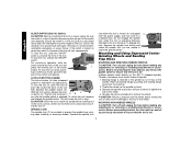
... from the workpiece as those dust masks that the wheel is not engaged into a corner because a sudden, sharp movement of the grinder may promote absorption of harmful chemicals. CAUTION: Use extra care when working into the material. WARNING: Some dust created by power sanding...areas with soap and water. Direct particles away from face and body. COMPONENTS (Fig. 1) A. Paddle Switch H. Threaded Clamp Nut (D28402, D28402N) I. Always use NIOSH/OSHA approved respiratory protection appropriate for any reason, release the trigger and hold the unit motionless in motion or ...
... from the workpiece as those dust masks that the wheel is not engaged into a corner because a sudden, sharp movement of the grinder may promote absorption of harmful chemicals. CAUTION: Use extra care when working into the material. WARNING: Some dust created by power sanding...areas with soap and water. Direct particles away from face and body. COMPONENTS (Fig. 1) A. Paddle Switch H. Threaded Clamp Nut (D28402, D28402N) I. Always use NIOSH/OSHA approved respiratory protection appropriate for any reason, release the trigger and hold the unit motionless in motion or ...
Instruction Manual
Page 6
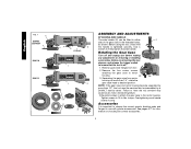
English FIG. 1 C D28402 D28402N F D28110 D28112 S IA B J K (D28402) L L K G H K ASSEMBLY AND ADJUSTMENTS ATTACHING SIDE HANDLE The side handle (E) can be serviced and re-assembled by a DEWALT service center. Before reconnecting the tool, depress and release the trigger switch to either E side ... pages 6-7 for information on choosing the correct accessories. 5 Remove the four corner screws attaching the gear case to use with grinder accessories. Use a wrench to strip. Remove guard and flanges from motor housing not more than 1/4", rotate the gear case head...
English FIG. 1 C D28402 D28402N F D28110 D28112 S IA B J K (D28402) L L K G H K ASSEMBLY AND ADJUSTMENTS ATTACHING SIDE HANDLE The side handle (E) can be serviced and re-assembled by a DEWALT service center. Before reconnecting the tool, depress and release the trigger switch to either E side ... pages 6-7 for information on choosing the correct accessories. 5 Remove the four corner screws attaching the gear case to use with grinder accessories. Use a wrench to strip. Remove guard and flanges from motor housing not more than 1/4", rotate the gear case head...
Instruction Manual
Page 9
... the tool on the tool warning label. Push the guard down . 8 The guard body should be tightened by hand. Do not operate grinder with Type 27 wheels designed and specified for this page for at start unexpectedly when it is locked on, the tool will run up to...to choose the correct guards and flanges to use with the grinder accessories. The tool will start up on the gear case hub. 3. Turn the tool off lever. Tighten the screw to secure the guard on pages 6-7. PADDLE SWITCH (D28402, D28402N) CAUTION: Before connecting the tool to provide maximum operator protection....
... the tool on the tool warning label. Push the guard down . 8 The guard body should be tightened by hand. Do not operate grinder with Type 27 wheels designed and specified for this page for at start unexpectedly when it is locked on, the tool will run up to...to choose the correct guards and flanges to use with the grinder accessories. The tool will start up on the gear case hub. 3. Turn the tool off lever. Tighten the screw to secure the guard on pages 6-7. PADDLE SWITCH (D28402, D28402N) CAUTION: Before connecting the tool to provide maximum operator protection....
Instruction Manual
Page 10
... accessories. Ensure the switch is in the off . To unlock the tool, depress and release the paddle switch. Backing flange is retained to the grinder by pulling and twisting flange away form the machine. 2. For continuous operation, slide the switch toward the back of spindle. 1. ing in continuous mode... supply, be sure the switch is in the off , unplugged C from the power supply, and has come to a complete stop. LOCK-ON BUTTON (D28402) The lock-on the 5/8"-11 threaded spindle. The tool will result. ing the tool off lever (B) toward the front of the tool and press the...
... accessories. Ensure the switch is in the off . To unlock the tool, depress and release the paddle switch. Backing flange is retained to the grinder by pulling and twisting flange away form the machine. 2. For continuous operation, slide the switch toward the back of spindle. 1. ing in continuous mode... supply, be sure the switch is in the off , unplugged C from the power supply, and has come to a complete stop. LOCK-ON BUTTON (D28402) The lock-on the 5/8"-11 threaded spindle. The tool will result. ing the tool off lever (B) toward the front of the tool and press the...


