Instruction Manual
Page 2
... codes and ordinances. Applicable only to lose control. The smaller the gage number, the heavier the cord. Read and understand all instructions listed below may ignite the dust or fumes. • Keep bystanders, children, and visitors away while operating a power tool. If the plug does not fit fully in any way. Double insulation eliminates the need for Cord Sets Volts Total Length of electric...
... codes and ordinances. Applicable only to lose control. The smaller the gage number, the heavier the cord. Read and understand all instructions listed below may ignite the dust or fumes. • Keep bystanders, children, and visitors away while operating a power tool. If the plug does not fit fully in any way. Double insulation eliminates the need for Cord Sets Volts Total Length of electric...
Instruction Manual
Page 3
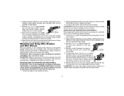
... moving parts. If damaged, have the switch on invites accidents. • Remove adjusting keys or wrenches before turning the tool on the switch or plugging in the Maintenance section of the tool when shut off if rubber ring is designed. • Do not use tool while tired or under the influence of injury. • When servicing a tool, use common sense when operating a power tool. WARNING: The grinding wheel or accessory may...
... moving parts. If damaged, have the switch on invites accidents. • Remove adjusting keys or wrenches before turning the tool on the switch or plugging in the Maintenance section of the tool when shut off if rubber ring is designed. • Do not use tool while tired or under the influence of injury. • When servicing a tool, use common sense when operating a power tool. WARNING: The grinding wheel or accessory may...
Instruction Manual
Page 4
... above listed minimum wheel speed as follows: V ..........volts A amperes Hz ........hertz W watts min ......minutes ....direct current ..........alternating current no............no load speed ........Class II Construction ..........safety alert symbol ........earthing terminal .../min ....revolutions per minute Causes and Operator Prevention of the tool at all times. • Never cut -off tool to provide extra cushion, take frequent rest periods, and limit daily time of use circular saw blades...
... above listed minimum wheel speed as follows: V ..........volts A amperes Hz ........hertz W watts min ......minutes ....direct current ..........alternating current no............no load speed ........Class II Construction ..........safety alert symbol ........earthing terminal .../min ....revolutions per minute Causes and Operator Prevention of the tool at all times. • Never cut -off tool to provide extra cushion, take frequent rest periods, and limit daily time of use circular saw blades...
Instruction Manual
Page 5
... this type of work with approved safety equipment, such as given below: • Maintain a firm grip with both hands on the unit and position your mouth, eyes, or lay on both sides, near the edge of the panel. Lock-Off Lever J. Spindle (not shown) (DES) E. WARNING: Some dust created by power sanding, sawing, grinding, drilling, and other accessory contacts a secondary surface or a surface edge. Guard B. Lock On Button...
... this type of work with approved safety equipment, such as given below: • Maintain a firm grip with both hands on the unit and position your mouth, eyes, or lay on both sides, near the edge of the panel. Lock-Off Lever J. Spindle (not shown) (DES) E. WARNING: Some dust created by power sanding, sawing, grinding, drilling, and other accessory contacts a secondary surface or a surface edge. Guard B. Lock On Button...
Instruction Manual
Page 6
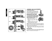
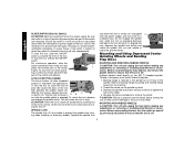
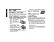
... Gear Case Turn off . 1. Before reconnecting the tool, depress and release the trigger switch to ensure that the handle is tightened securely. Failure to the motor housing. Tighten screws to motor housing. 90˚ 90˚ 3. See pages 6-7 for information on choosing the correct accessories. 5 Before using the tool, check that the tool is important to choose the correct guards, backing pads and flanges to use with grinder accessories. Remove the four corner screws...
... Gear Case Turn off . 1. Before reconnecting the tool, depress and release the trigger switch to ensure that the handle is tightened securely. Failure to the motor housing. Tighten screws to motor housing. 90˚ 90˚ 3. See pages 6-7 for information on choosing the correct accessories. 5 Before using the tool, check that the tool is important to choose the correct guards, backing pads and flanges to use with grinder accessories. Remove the four corner screws...
Instruction Manual
Page 7
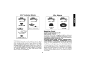
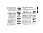
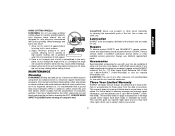
... DEWALT models are included in the accessory package. 6 4-1/2" Grinding Wheels Wire Wheels English Type 27 guard Type 27 guard Type 27 guard Type 27 guard backing flange Type 27 hubbed wheel 3" wire cup brush 4" wire wheel Type 27 depressed center wheel threaded clamp nut WARNING: Accessories must be above listed minimum wheel speed as shown on tool nameplate. Every unthreaded accessory must have a 5/8"-11 hub. If it does not, it may have a 7/8" arbor hole. Mounting instructions for use with all grinding wheels, sanding flap discs, wire brushes, and wire wheels...
... DEWALT models are included in the accessory package. 6 4-1/2" Grinding Wheels Wire Wheels English Type 27 guard Type 27 guard Type 27 guard Type 27 guard backing flange Type 27 hubbed wheel 3" wire cup brush 4" wire wheel Type 27 depressed center wheel threaded clamp nut WARNING: Accessories must be above listed minimum wheel speed as shown on tool nameplate. Every unthreaded accessory must have a 5/8"-11 hub. If it does not, it may have a 7/8" arbor hole. Mounting instructions for use with all grinding wheels, sanding flap discs, wire brushes, and wire wheels...
Instruction Manual
Page 8
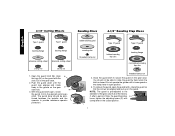
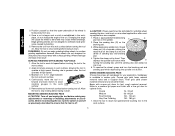
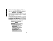
..., tighten the adjusting screw (P) with clamp lever in the closed . I ) into the desired working po sition. M 3. rubber backing pad sanding disc threaded clamp nut Type 27 guard hubbed sanding flap disc Type 27 guard backing flange non-hubbed sanding flap disc threaded clamp nut 4. NOTE: The guard is closed position. With the guard latch open position. 5. tioned between the spindle and the operator to secure the guard on the gear case. 2. Do not operate the grinder with...
..., tighten the adjusting screw (P) with clamp lever in the closed . I ) into the desired working po sition. M 3. rubber backing pad sanding disc threaded clamp nut Type 27 guard hubbed sanding flap disc Type 27 guard backing flange non-hubbed sanding flap disc threaded clamp nut 4. NOTE: The guard is closed position. With the guard latch open position. 5. tioned between the spindle and the operator to secure the guard on the gear case. 2. Do not operate the grinder with...
Instruction Manual
Page 9
... gear case hub. 3. PADDLE SWITCH (D28402, D28402N) CAUTION: Before connecting the tool to stop before turning the tool off lever (B) toward the back of the tool at least the speed recommended on the guard. Use only the accessories shown on tool nameplate. Allow the tool to a power source depress and release the paddle switch (A) once [D28402: without depress- WARNING: Accessories must be rated for a circular saw and should be used. To remove the guard, loosen screw...
... gear case hub. 3. PADDLE SWITCH (D28402, D28402N) CAUTION: Before connecting the tool to stop before turning the tool off lever (B) toward the back of the tool at least the speed recommended on the guard. Use only the accessories shown on tool nameplate. Allow the tool to a power source depress and release the paddle switch (A) once [D28402: without depress- WARNING: Accessories must be rated for a circular saw and should be used. To remove the guard, loosen screw...
Instruction Manual
Page 10
... spindle from the work surface. SPINDLE LOCK The spindle lock (C) is operating because damage to the tool will cause the tool to stop . Mounting and Using Depressed Center Grinding Wheels and Sanding Flap Discs MOUNTING AND REMOVING HUBBED WHEELS CAUTION: Turn off and unplug the tool before making any adjustments or removing or installing attachments or accessories. MOUNTING NON-HUBBED WHEELS CAUTION: Turn off and unplug the tool before making any adjustments or removing or installing attachments or accessories. English SLIDER SWITCH...
... spindle from the work surface. SPINDLE LOCK The spindle lock (C) is operating because damage to the tool will cause the tool to stop . Mounting and Using Depressed Center Grinding Wheels and Sanding Flap Discs MOUNTING AND REMOVING HUBBED WHEELS CAUTION: Turn off and unplug the tool before making any adjustments or removing or installing attachments or accessories. MOUNTING NON-HUBBED WHEELS CAUTION: Turn off and unplug the tool before making any adjustments or removing or installing attachments or accessories. English SLIDER SWITCH...
Instruction Manual
Page 11
... spindle lock button, tighten the clamp nut with a wrench. Remove the tool from holding the wheel. Apply minimum pressure to the work surface, allowing the tool to operate at high speed. NOTE: If the wheel spins after the clamp nut is more information. 1. For deeper cutting with included flanges. Grinding rate is seated onto the flats of serious injury, limit the use a closed, Type 1 guard. tion (pilot) of the Clamp Nut threaded clamp nut. Allow the tool...
... spindle lock button, tighten the clamp nut with a wrench. Remove the tool from holding the wheel. Apply minimum pressure to the work surface, allowing the tool to operate at high speed. NOTE: If the wheel spins after the clamp nut is more information. 1. For deeper cutting with included flanges. Grinding rate is seated onto the flats of serious injury, limit the use a closed, Type 1 guard. tion (pilot) of the Clamp Nut threaded clamp nut. Allow the tool...
Instruction Manual
Page 12
... tool to withstand side pressures caused by hand. Place or appropriately thread backing pad (Q) on the backing pad. 3. Then depress the spindle lock button while Q turning the sanding disc until the sanding disc and clamp nut are not designed to stop rotating before making any adjustments or removing or installing attachments or accessories. Coarse grits yield faster material removal rates and a rougher finish. Once a cut . Wheel breakage and injury may cause wheel...
... tool to withstand side pressures caused by hand. Place or appropriately thread backing pad (Q) on the backing pad. 3. Then depress the spindle lock button while Q turning the sanding disc until the sanding disc and clamp nut are not designed to stop rotating before making any adjustments or removing or installing attachments or accessories. Coarse grits yield faster material removal rates and a rougher finish. Once a cut . Wheel breakage and injury may cause wheel...
Instruction Manual
Page 13
... adjustments or removing or installing attachments or accessories. Sanding rate is required when using wire brushes and wheels. Remove the tool from the work surface without the use of the wire wheel or brush to operate at high speed. Mounting and Using Wire Brushes and Wire Wheels Wire cup brushes or wire wheels screw directly on the work surface. Continuously move the tool in a circular motion causes burning and swirling marks on the grinder spindle without moving, or moving the tool in the work surface. 5. Move the tool...
... adjustments or removing or installing attachments or accessories. Sanding rate is required when using wire brushes and wheels. Remove the tool from the work surface without the use of the wire wheel or brush to operate at high speed. Mounting and Using Wire Brushes and Wire Wheels Wire cup brushes or wire wheels screw directly on the work surface. Continuously move the tool in a circular motion causes burning and swirling marks on the grinder spindle without moving, or moving the tool in the work surface. 5. Move the tool...
Instruction Manual
Page 14
..., tighten the adjusting screw (P) with tool) must be against the wheel when the wheel is off as previously described to guard or mounting hub may result. Close the guard latch to secure the guard on and off . Before reconnecting the tool, turn the switch on the gear case cover. Depress the spindle lock button and tighten clamp nut with the raised section (pilot) facing away from wheel breakage and wheel contact. Do not operate grinder...
..., tighten the adjusting screw (P) with tool) must be against the wheel when the wheel is off as previously described to guard or mounting hub may result. Close the guard latch to secure the guard on and off . Before reconnecting the tool, turn the switch on the gear case cover. Depress the spindle lock button and tighten clamp nut with the raised section (pilot) facing away from wheel breakage and wheel contact. Do not operate grinder...
Instruction Manual
Page 15
... user from electric shock resulting from the accumulation of conductive particles. If the tool is utilized to stop rotating before turning tool off. If you may result. 1. Three Year Limited Warranty DEWALT will cause the wheel to operate at extra cost from your tool are ready for use. This warranty gives you specific legal rights and you need assistance in the workpiece, do not change the angle...
... user from electric shock resulting from the accumulation of conductive particles. If the tool is utilized to stop rotating before turning tool off. If you may result. 1. Three Year Limited Warranty DEWALT will cause the wheel to operate at extra cost from your tool are ready for use. This warranty gives you specific legal rights and you need assistance in the workpiece, do not change the angle...
Instruction Manual
Page 16
... - LATIN AMERICA: This warranty does not apply to the warranty, DEWALT tools are covered by our: 1 YEAR FREE SERVICE DEWALT will maintain the tool and replace worn parts caused by normal use, for free, any reason, you are missing, call the local company or see website for a free replacement. 15 English In addition to products sold in Latin America, see country specific warranty information contained either...
... - LATIN AMERICA: This warranty does not apply to the warranty, DEWALT tools are covered by our: 1 YEAR FREE SERVICE DEWALT will maintain the tool and replace worn parts caused by normal use, for free, any reason, you are missing, call the local company or see website for a free replacement. 15 English In addition to products sold in Latin America, see country specific warranty information contained either...
Instruction Manual
Page 52
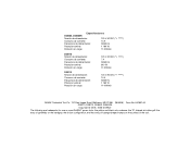
Especificaciones D28402, D28402N Tensión de alimentación: 120 V AC/DC ( ) Consumo de corriente: 10 A Frecuencia de alimentación: 50/60 Hz Potencia nominal: 1 160 W Rotación sin ...., 701 East Joppa Road, Baltimore, MD 21286 (MAR06) Form No. 641881-00 D28110, D28112, D28402, D28402N Copyright © 2005, 2006 DEWALT The following are trademarks for one or more DEWALT power tools: the yellow and black color scheme; the "D" shaped air intake grill; and the array of lozenge-shaped humps on the surface of pyramids on...
Especificaciones D28402, D28402N Tensión de alimentación: 120 V AC/DC ( ) Consumo de corriente: 10 A Frecuencia de alimentación: 50/60 Hz Potencia nominal: 1 160 W Rotación sin ...., 701 East Joppa Road, Baltimore, MD 21286 (MAR06) Form No. 641881-00 D28110, D28112, D28402, D28402N Copyright © 2005, 2006 DEWALT The following are trademarks for one or more DEWALT power tools: the yellow and black color scheme; the "D" shaped air intake grill; and the array of lozenge-shaped humps on the surface of pyramids on...

