
Instruction Manual
Page 5
... known to remove the unit from face and body. Allowing dust to a complete stop. COMPONENTS (Fig. 1) A. Threaded Clamp Nut (D28402, D28402N) I. Slider Switch (D28110, F. 4-1/2" Grinding Wheel D28112) G. Investigate and take corrective actions to eliminate the cause of wheel binding. • When restarting...and hold the unit motionless in motion or kickback may cause serious and permanent respiratory or other reproductive harm. Paddle Switch H. Lock On Button (D28402) C. Kickback forces can be controlled by the operator, if proper precautions are : • lead from lead-...
... known to remove the unit from face and body. Allowing dust to a complete stop. COMPONENTS (Fig. 1) A. Threaded Clamp Nut (D28402, D28402N) I. Slider Switch (D28110, F. 4-1/2" Grinding Wheel D28112) G. Investigate and take corrective actions to eliminate the cause of wheel binding. • When restarting...and hold the unit motionless in motion or kickback may cause serious and permanent respiratory or other reproductive harm. Paddle Switch H. Lock On Button (D28402) C. Kickback forces can be controlled by the operator, if proper precautions are : • lead from lead-...
Instruction Manual
Page 6
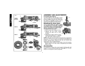
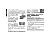
...head to desired position. English FIG. 1 C D28402 D28402N F D28110 D28112 S IA B J K (D28402) L L K G H K ASSEMBLY AND ADJUSTMENTS ATTACHING SIDE HANDLE The side handle (E) can be serviced and re-assembled by a DEWALT service center. Use a wrench to have the ...tool serviced may cause brush, motor and bearing failure. 3. Before reconnecting the tool, depress and release the trigger switch...
...head to desired position. English FIG. 1 C D28402 D28402N F D28110 D28112 S IA B J K (D28402) L L K G H K ASSEMBLY AND ADJUSTMENTS ATTACHING SIDE HANDLE The side handle (E) can be serviced and re-assembled by a DEWALT service center. Use a wrench to have the ...tool serviced may cause brush, motor and bearing failure. 3. Before reconnecting the tool, depress and release the trigger switch...
Instruction Manual
Page 7
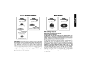
... shown on pages 6-7 of this manual. The tool may burst and cause injury. Use only the accessories shown on tool nameplate. Some DEWALT models are included in the accessory package. 6 Mounting instructions for these accessory guards are provided with a guard intended for a circular saw... it does not, it may have a 5/8"-11 hub. Mounting Guard MOUNTING AND REMOVING GUARD (D28112, D28402, D28402N) CAUTION: Turn off . Before reconnecting the tool, depress and release the paddle switch to ensure that the tool is designed for at least the speed recommended on the tool warning label....
... shown on pages 6-7 of this manual. The tool may burst and cause injury. Use only the accessories shown on tool nameplate. Some DEWALT models are included in the accessory package. 6 Mounting instructions for these accessory guards are provided with a guard intended for a circular saw... it does not, it may have a 5/8"-11 hub. Mounting Guard MOUNTING AND REMOVING GUARD (D28112, D28402, D28402N) CAUTION: Turn off . Before reconnecting the tool, depress and release the paddle switch to ensure that the tool is designed for at least the speed recommended on the tool warning label....
Instruction Manual
Page 9
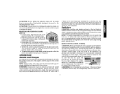
... it may burst and cause injury. Make sure the wheel has come to a power source depress and release the paddle switch (A) once [D28402: without depress- PADDLE SWITCH (D28402, D28402N) CAUTION: Before connecting the tool to a complete stop rotating before laying the tool down . 8 ing the lock-on...and the operator to full speed before turning the tool off lever (B) toward the back of the tool, then depress the paddle switch (A). If the paddle switch is disabled, the tool may result. MOUNTING AND REMOVING GUARD (D28110) O N 1. Wheels and other accessories running over rated...
... it may burst and cause injury. Make sure the wheel has come to a power source depress and release the paddle switch (A) once [D28402: without depress- PADDLE SWITCH (D28402, D28402N) CAUTION: Before connecting the tool to a complete stop rotating before laying the tool down . 8 ing the lock-on...and the operator to full speed before turning the tool off lever (B) toward the back of the tool, then depress the paddle switch (A). If the paddle switch is disabled, the tool may result. MOUNTING AND REMOVING GUARD (D28110) O N 1. Wheels and other accessories running over rated...
Instruction Manual
Page 10
..., such as the activation of a ground fault interrupter, throwing of the wheel. 4. LOCK-ON BUTTON (D28402) The lock-on the spindle. To unlock the tool, depress and release the paddle switch. ing the tool off . To engage the lock, depress the spindle lock button and rotate the spindle ...failure. CAUTION: Failure to properly seat the wheel before turning the tool on , push the lock-off and unplug the tool before turn the switch on when the power is connected, the tool will result. This will continue to a complete stop . Before reconnecting the tool, depress and release...
..., such as the activation of a ground fault interrupter, throwing of the wheel. 4. LOCK-ON BUTTON (D28402) The lock-on the spindle. To unlock the tool, depress and release the paddle switch. ing the tool off . To engage the lock, depress the spindle lock button and rotate the spindle ...failure. CAUTION: Failure to properly seat the wheel before turning the tool on , push the lock-off and unplug the tool before turn the switch on when the power is connected, the tool will result. This will continue to a complete stop . Before reconnecting the tool, depress and release...


