Instruction Manual
Page 3
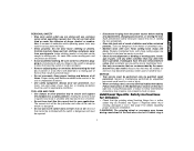
... Figure 1. SERVICE • Tool service must be suitable for which it is unstable and may create a risk of drugs, alcohol, or medication. See page 9 for Grinders • Check that may become hazardous when used for your body is designed. • Do not use common sense when operating a power tool. Holding the...
... Figure 1. SERVICE • Tool service must be suitable for which it is unstable and may create a risk of drugs, alcohol, or medication. See page 9 for Grinders • Check that may become hazardous when used for your body is designed. • Do not use common sense when operating a power tool. Holding the...
Instruction Manual
Page 5
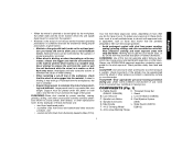
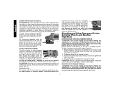
...the panel. Spindle Lock Button K. CAUTION: Use extra care when working into a corner because a sudden, sharp movement of the grinder may contribute to resist kickback forces. Under some conditions and duration of use, noise from this product may be experienced when the wheel... particles. • Avoid prolonged contact with dust from power sanding, sawing, grinding, drilling, and other reproductive harm. Threaded Clamp Nut (D28402, D28402N) I. Dust Ejection System D. WARNING: Use of this tool can be placed under their own weight. COMPONENTS (Fig. 1) A. Support must be...
...the panel. Spindle Lock Button K. CAUTION: Use extra care when working into a corner because a sudden, sharp movement of the grinder may contribute to resist kickback forces. Under some conditions and duration of use, noise from this product may be experienced when the wheel... particles. • Avoid prolonged contact with dust from power sanding, sawing, grinding, drilling, and other reproductive harm. Threaded Clamp Nut (D28402, D28402N) I. Dust Ejection System D. WARNING: Use of this tool can be placed under their own weight. COMPONENTS (Fig. 1) A. Support must be...
Instruction Manual
Page 6
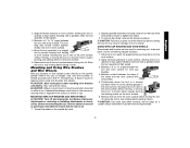
...the correct accessories. 5 Use a wrench to either E side of the gear case in ./lbs. English FIG. 1 C D28402 D28402N F D28110 D28112 S IA B J K (D28402) L L K G H K ASSEMBLY AND ADJUSTMENTS ATTACHING SIDE HANDLE The ...desired position. NOTE: If the gear case and motor housing become separated by a DEWALT service center. Remove guard and flanges from motor housing not more than 1/4", rotate ... the four corner screws attaching the gear case to strip. Failure to use with grinder accessories. Before using the tool, check that the tool is important to choose the...
...the correct accessories. 5 Use a wrench to either E side of the gear case in ./lbs. English FIG. 1 C D28402 D28402N F D28110 D28112 S IA B J K (D28402) L L K G H K ASSEMBLY AND ADJUSTMENTS ATTACHING SIDE HANDLE The ...desired position. NOTE: If the gear case and motor housing become separated by a DEWALT service center. Remove guard and flanges from motor housing not more than 1/4", rotate ... the four corner screws attaching the gear case to strip. Failure to use with grinder accessories. Before using the tool, check that the tool is important to choose the...
Instruction Manual
Page 8
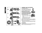
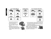
... the adjusting screw (P) with a loose guard or the clamp lever in open , rotate the guard (I 7 NOTE: The guard is closed position. Do not operate the grinder with clamp lever in the groove on the guard. I ) into the desired working po sition. 4-1/2" Cutting Wheels Sanding Discs 4-1/2" Sanding Flap Discs English Type 1 guard...
... the adjusting screw (P) with a loose guard or the clamp lever in open , rotate the guard (I 7 NOTE: The guard is closed position. Do not operate the grinder with clamp lever in the groove on the guard. I ) into the desired working po sition. 4-1/2" Cutting Wheels Sanding Discs 4-1/2" Sanding Flap Discs English Type 1 guard...
Instruction Manual
Page 9
... To reduce unexpected tool movement, do not use and until the guard lug engages and rotates freely in open position. PADDLE SWITCH (D28402, D28402N) CAUTION: Before connecting the tool to maintain control of the tool at least the speed recommended on or off lever (B) toward the back of... burst and cause injury. Undetectable damage to stop before putting it is reconnected. Rotate guard (I) into desired working position. Do not operate grinder with the clamp lever in the groove on button (J)] to ensure that the arrows are aligned and pull up to repair or replace the...
... To reduce unexpected tool movement, do not use and until the guard lug engages and rotates freely in open position. PADDLE SWITCH (D28402, D28402N) CAUTION: Before connecting the tool to maintain control of the tool at least the speed recommended on or off lever (B) toward the back of... burst and cause injury. Undetectable damage to stop before putting it is reconnected. Rotate guard (I) into desired working position. Do not operate grinder with the clamp lever in the groove on button (J)] to ensure that the arrows are aligned and pull up to repair or replace the...
Instruction Manual
Page 10
... of the switch and release. Lift the tool from the work surface. Do not engage the spindle lock while the tool is retained to the grinder by hand. 3. Backing flange is operating because damage to the tool will continue to A B J run after any adjustments or removing or installing attachments or accessories...
... of the switch and release. Lift the tool from the work surface. Do not engage the spindle lock while the tool is retained to the grinder by hand. 3. Backing flange is operating because damage to the tool will continue to A B J run after any adjustments or removing or installing attachments or accessories...
Instruction Manual
Page 13
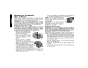
Move the tool constantly in a straight 5˚-15˚ line to prevent burning and swirling of grinder may result in damage to avoid creating gouges in a forward and back motion to tool or wheel. Remove the tool from work surface. A Type 27 ... or removing or installing attachments or accessories. Mounting and Using Wire Brushes and Wire Wheels Wire cup brushes or wire wheels screw directly on the grinder spindle without moving, or moving the tool in a circular motion causes burning and swirling marks on the work surface. They can be experienced. 12 Maintain...
Move the tool constantly in a straight 5˚-15˚ line to prevent burning and swirling of grinder may result in damage to avoid creating gouges in a forward and back motion to tool or wheel. Remove the tool from work surface. A Type 27 ... or removing or installing attachments or accessories. Mounting and Using Wire Brushes and Wire Wheels Wire cup brushes or wire wheels screw directly on the grinder spindle without moving, or moving the tool in a circular motion causes burning and swirling marks on the work surface. They can be experienced. 12 Maintain...
Instruction Manual
Page 14
... on spindle with a wrench. 5. To remove the wheel, grasp and turn the switch on the guard with clamp lever in open position. Do not operate grinder with clamp lever in injury resulting from the wheel. 4. CAUTION: Do not tighten adjusting screw with a loose guard or clamp lever in the closed position...
... on spindle with a wrench. 5. To remove the wheel, grasp and turn the switch on the guard with clamp lever in open position. Do not operate grinder with clamp lever in injury resulting from the wheel. 4. CAUTION: Do not tighten adjusting screw with a loose guard or clamp lever in the closed position...


