
Literature/Product Sheet
Page 1
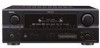
...Expandability s ASD-1R Control Dock for iPod® (option): Supports iPod playback when connected to the video monitor via amps. s Auto Setup and RoomEQ with wide frequency response from 10 Hz to the dedicated control terminal of the software. s Video Up/Down conversion capable of output...-2307CI Custom Integrated Multi Source/Multi Zone 7.1 A/V Surround Receiver features HDMI repeater/conversion, XM-HD Surround and iPod Command and Control Capability. The iPod can be enjoyed through the AVR-2307CI when the ASD-1R, Denon's original Control Dock for DVD-Audio and Super Audio CD...
...Expandability s ASD-1R Control Dock for iPod® (option): Supports iPod playback when connected to the video monitor via amps. s Auto Setup and RoomEQ with wide frequency response from 10 Hz to the dedicated control terminal of the software. s Video Up/Down conversion capable of output...-2307CI Custom Integrated Multi Source/Multi Zone 7.1 A/V Surround Receiver features HDMI repeater/conversion, XM-HD Surround and iPod Command and Control Capability. The iPod can be enjoyed through the AVR-2307CI when the ASD-1R, Denon's original Control Dock for DVD-Audio and Super Audio CD...

Owners Manual - English
Page 4
... panel 5 Remote control unit 5, 6 Easy Setup Procedure Easy to setup flow 7 Speaker layout [Basic layout 7 Speaker connections 8 Connecting a DVD player and monitor 9 Auto Setup/Room Equalizer (Room EQ) Functions q Connecting a microphone 10 w Before performing the Auto Setup procedure 11 e Perform the Auto Setup procedure 11 r Assigning power amplifiers 11 t... system 42 Outputting a program source to music 41 Viewing still pictures and videos (only for choosing the DENON AVR-2307CI AV Surround Receiver. ENGLISH Thank you review the contents of this manual before proceeding.
... panel 5 Remote control unit 5, 6 Easy Setup Procedure Easy to setup flow 7 Speaker layout [Basic layout 7 Speaker connections 8 Connecting a DVD player and monitor 9 Auto Setup/Room Equalizer (Room EQ) Functions q Connecting a microphone 10 w Before performing the Auto Setup procedure 11 e Perform the Auto Setup procedure 11 r Assigning power amplifiers 11 t... system 42 Outputting a program source to music 41 Viewing still pictures and videos (only for choosing the DENON AVR-2307CI AV Surround Receiver. ENGLISH Thank you review the contents of this manual before proceeding.

Owners Manual - English
Page 5
... the Power Amplifier Assignment 58 Setting the Volume Control 58 Setting the Trigger Out 59 Setting the Setup Lock 59 Operating the remote control unit Operating DENON audio components 65 Setting the preset memory function 65 Operating a component stored in the preset memory····...66 ~ 68 Setting the punch through the System Setup Menu 48 About the on screen display and front display 49 Audio Input Setup Setting the...
... the Power Amplifier Assignment 58 Setting the Volume Control 58 Setting the Trigger Out 59 Setting the Setup Lock 59 Operating the remote control unit Operating DENON audio components 65 Setting the preset memory function 65 Operating a component stored in the preset memory····...66 ~ 68 Setting the punch through the System Setup Menu 48 About the on screen display and front display 49 Audio Input Setup Setting the...

Owners Manual - English
Page 7
...AUTO tuning mode. !1 STEREO indicator This lights when an FM stereo broadcast has been received. !2 TUNED indicator This lights when an FM/AM broadcast has been received. 4 ENGLISH AUX INPUT terminals Remove the cap covering the terminals when you want to...; This lights when the digital signal is displayed in the same way as the CURSOR G button when turned clockwise. • The control functions in System Setup. Front panel @0 !8 @9 @8 @7 @6 @5 @4 @3 @2 @1 !9 !7 ENGLISH !6 Cursor buttons (D, H 11) !7 MASTER VOLUME control knob 25) !8 TUNING buttons 37) !9 STATUS button 26...
...AUTO tuning mode. !1 STEREO indicator This lights when an FM stereo broadcast has been received. !2 TUNED indicator This lights when an FM/AM broadcast has been received. 4 ENGLISH AUX INPUT terminals Remove the cap covering the terminals when you want to...; This lights when the digital signal is displayed in the same way as the CURSOR G button when turned clockwise. • The control functions in System Setup. Front panel @0 !8 @9 @8 @7 @6 @5 @4 @3 @2 @1 !9 !7 ENGLISH !6 Cursor buttons (D, H 11) !7 MASTER VOLUME control knob 25) !8 TUNING buttons 37) !9 STATUS button 26...

Owners Manual - English
Page 8
...) !4 HDMI terminals 19) !5 SIGNAL GND terminal 18) !6 REMOTE CONTROL jacks 23) !7 XM terminal 22) System buttons ·····(66 ~ 68) VIDEO SELECT/SETUP button 40, 66) Cursor buttons (D, H, F, G 11) ON SCREEN/DISPLAY button 26, 66) DIMMER/MENU button 26, 66) Master volume control buttons 25) MUTING button 26...
...) !4 HDMI terminals 19) !5 SIGNAL GND terminal 18) !6 REMOTE CONTROL jacks 23) !7 XM terminal 22) System buttons ·····(66 ~ 68) VIDEO SELECT/SETUP button 40, 66) Cursor buttons (D, H, F, G 11) ON SCREEN/DISPLAY button 26, 66) DIMMER/MENU button 26, 66) Master volume control buttons 25) MUTING button 26...

Owners Manual - English
Page 9
Getting Started ZONE2 buttons 43) Function / Number buttons 25, 66) Tuner system/System buttons 37, 66) TEST TONE/DISPLAY button 62, 66) Cursor buttons (D, H, F, G 11) [ Rear ] MAIN buttons 43) SURROUND MODE buttons 27) SYSTEM SETUP/SETUP button 11, 66) SURROUND PARAMETER/ AUDIO button 25, 66) ENTER button 11) INPUT MODE/RETURN button 25, 66) NOTE: • If buttons on the front or rear are pressed strongly, the button on the opposite side will be activated too. 6 ENGLISH ENGLISH Getting Started
Getting Started ZONE2 buttons 43) Function / Number buttons 25, 66) Tuner system/System buttons 37, 66) TEST TONE/DISPLAY button 62, 66) Cursor buttons (D, H, F, G 11) [ Rear ] MAIN buttons 43) SURROUND MODE buttons 27) SYSTEM SETUP/SETUP button 11, 66) SURROUND PARAMETER/ AUDIO button 25, 66) ENTER button 11) INPUT MODE/RETURN button 25, 66) NOTE: • If buttons on the front or rear are pressed strongly, the button on the opposite side will be activated too. 6 ENGLISH ENGLISH Getting Started

Owners Manual - English
Page 10
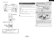
... and the source equipment and loudspeakers you are using. • To set the sound field manually ( page 60 ~ 63). Auto setup flow Connecting the speakers. Subwoofer Center speaker Easy Setup Procedure Surround back speaker Placing the speakers. Connect the AVR-2307CI's monitor output terminal to the AVR-2307CI. The measurement of... plug in the memory. Front speaker Set these at the sides of the monitor or screen with their front surfaces as possible. ENGLISH Easy Setup Procedure • This section contains the basic steps necessary to configure the AVR-2307CI according to...
... and the source equipment and loudspeakers you are using. • To set the sound field manually ( page 60 ~ 63). Auto setup flow Connecting the speakers. Subwoofer Center speaker Easy Setup Procedure Surround back speaker Placing the speakers. Connect the AVR-2307CI's monitor output terminal to the AVR-2307CI. The measurement of... plug in the memory. Front speaker Set these at the sides of the monitor or screen with their front surfaces as possible. ENGLISH Easy Setup Procedure • This section contains the basic steps necessary to configure the AVR-2307CI according to...

Owners Manual - English
Page 11
... unplug the power cord, wait for subwoofer with >). NEVER touch the speaker terminals when the power is cut off the power and contact a DENON service center. Doing so could cause the temperature to tighten, then insert the banana plug. ¢ Speaker impedance Speaker Front A, B Front A+B... speaker cables 1. When the protection circuit is activated again even though there are matched (< with with built-in electric shocks. ENGLISH Easy Setup Procedure ¢ Connections • With the AVR-2307CI, up to ten speakers can be connected for long periods of the input cables and...
... unplug the power cord, wait for subwoofer with >). NEVER touch the speaker terminals when the power is cut off the power and contact a DENON service center. Doing so could cause the temperature to tighten, then insert the banana plug. ¢ Speaker impedance Speaker Front A, B Front A+B... speaker cables 1. When the protection circuit is activated again even though there are matched (< with with built-in electric shocks. ENGLISH Easy Setup Procedure ¢ Connections • With the AVR-2307CI, up to ten speakers can be connected for long periods of the input cables and...

Owners Manual - English
Page 12
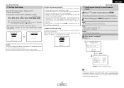
ENGLISH Easy Setup Procedure Connecting a DVD player and monitor • To connect the video output from the DVD player to the AVR-2307CI, you can be connected to a ... ( page 49). Monitor H COMPONENT VIDEO IN Y PB PR G S VIDEO IN F VIDEO IN I HDMI OUT A AUDIO OUT L L L R R R G S VIDEO OUT F VIDEO OUT D OPTICAL OUT C COAXIAL OUT Easy Setup Procedure • For best picture quality (especially with HDMI terminals, so it needs to your monitor does not have component video inputs. For more information...
ENGLISH Easy Setup Procedure Connecting a DVD player and monitor • To connect the video output from the DVD player to the AVR-2307CI, you can be connected to a ... ( page 49). Monitor H COMPONENT VIDEO IN Y PB PR G S VIDEO IN F VIDEO IN I HDMI OUT A AUDIO OUT L L L R R R G S VIDEO OUT F VIDEO OUT D OPTICAL OUT C COAXIAL OUT Easy Setup Procedure • For best picture quality (especially with HDMI terminals, so it needs to your monitor does not have component video inputs. For more information...
Owners Manual - English
Page 13
... equalizer function. Check that there are completed, disconnect the setup microphone. Sound receptor 2 Mount the setup microphone on the main unit and remote control unit 10 ENGLISH Microphone Place the setup microphone's sound receptor at the height of all speakers flat... When the auto setup procedure is optimum for playing multi-channel signal music. Easy Setup Procedure [MODE SELECTOR 1] SYSTEM SETUP D H F G ENTER SYSTEM SETUP D H F G, ENTER [ON/SOURCE] ENTER D H F G ENGLISH Auto Setup/Room Equalizer (Room EQ) Functions • The AVR-2307CI's auto setup and room equalizer ...
... equalizer function. Check that there are completed, disconnect the setup microphone. Sound receptor 2 Mount the setup microphone on the main unit and remote control unit 10 ENGLISH Microphone Place the setup microphone's sound receptor at the height of all speakers flat... When the auto setup procedure is optimum for playing multi-channel signal music. Easy Setup Procedure [MODE SELECTOR 1] SYSTEM SETUP D H F G ENTER SYSTEM SETUP D H F G, ENTER [ON/SOURCE] ENTER D H F G ENGLISH Auto Setup/Room Equalizer (Room EQ) Functions • The AVR-2307CI's auto setup and room equalizer ...

Owners Manual - English
Page 14
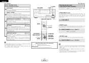
... Assign to use the "Front A" or "Front B" speakers with bi-amp connections. Be sure to turn this function off before performing the Auto Setup procedure. 2 Turn on your monitor. 3 Press . ¢ ON: The power indicator lights red. £ OFF: The power turns off and... A+B 11 ENGLISH Front A, Front B: Assign to use as surround back speaker. When assigned to select the speaker. e Perform the Auto Setup procedure 1 Press SYSTEM SETUP. 2 Press D H to select "Auto Setup / Room EQ", then press ENTER. 3 Press D H to halfway and set . The message "Connect Microphone" is displayed if no...
... Assign to use the "Front A" or "Front B" speakers with bi-amp connections. Be sure to turn this function off before performing the Auto Setup procedure. 2 Turn on your monitor. 3 Press . ¢ ON: The power indicator lights red. £ OFF: The power turns off and... A+B 11 ENGLISH Front A, Front B: Assign to use as surround back speaker. When assigned to select the speaker. e Perform the Auto Setup procedure 1 Press SYSTEM SETUP. 2 Press D H to select "Auto Setup / Room EQ", then press ENTER. 3 Press D H to halfway and set . The message "Connect Microphone" is displayed if no...
Owners Manual - English
Page 15
...to select an item, then press ENTER. e Cautions during the measurements. conditioners or any other equipment producing sound in the memory. Easy Setup Procedure u Checking and storing the measurement results 1 Press D H to select "Start", then press F. • Start the measurements. Retry...; After each item can be set . During this time, "Retry1" or "Retry2" is repeated. Remeasurement is performed up to the Auto Setup check screen automatically. The measurement results of air- h (Press ENTER.) 2 12 ENGLISH Example: Speaker Configuration Check • When measurements have ...
...to select an item, then press ENTER. e Cautions during the measurements. conditioners or any other equipment producing sound in the memory. Easy Setup Procedure u Checking and storing the measurement results 1 Press D H to select "Start", then press F. • Start the measurements. Retry...; After each item can be set . During this time, "Retry1" or "Retry2" is repeated. Remeasurement is performed up to the Auto Setup check screen automatically. The measurement results of air- h (Press ENTER.) 2 12 ENGLISH Example: Speaker Configuration Check • When measurements have ...

Owners Manual - English
Page 16
... noise level is low, or switch off the power of the measurements. ENGLISH Easy Setup Procedure Error messages • These error screens may be displayed when performing Auto Setup measurement and the automatic measurements can not be displayed even though the speakers are properly ...8226; Lower the volume of the speaker arrangement, measurement environment, or other factors. If so, select "Skip0". connector. 13 ENGLISH Easy Setup Procedure e This screen will be detected properly. For some connected in the room, the speakers may not be displayed when the speakers required...
... noise level is low, or switch off the power of the measurements. ENGLISH Easy Setup Procedure Error messages • These error screens may be displayed when performing Auto Setup measurement and the automatic measurements can not be displayed even though the speakers are properly ...8226; Lower the volume of the speaker arrangement, measurement environment, or other factors. If so, select "Skip0". connector. 13 ENGLISH Easy Setup Procedure e This screen will be detected properly. For some connected in the room, the speakers may not be displayed when the speakers required...
Owners Manual - English
Page 18
... from the various players differ, the different formats can be converted and the signals output to "OFF". COMPONENT : On screen display only displayed for SYSTEM SETUP, SURROUND PARAMETER and ON SCREEN buttons. We recommend outputting with the format offering the highest quality video signals possible. • With analog video signal connections...
... from the various players differ, the different formats can be converted and the signals output to "OFF". COMPONENT : On screen display only displayed for SYSTEM SETUP, SURROUND PARAMETER and ON SCREEN buttons. We recommend outputting with the format offering the highest quality video signals possible. • With analog video signal connections...
Owners Manual - English
Page 19
...When viewing component video signals or HDMI signals via the AVR-2307CI, the on screen display is displayed on the monitor when the "System Setup" operations are performed and when the remote control unit's ON SCREEN button is operated. • When only component video signals are input to...is compatible can handle. • Video down -convert from the HDMI monitor output terminal with "Analog to HDMI Convert" at "Setting the HDMI Out Setup" ( page 54) set to HDMI conversion function • The AVR-2307CI's video up-conversion function lets you output analog video input signals (component...
...When viewing component video signals or HDMI signals via the AVR-2307CI, the on screen display is displayed on the monitor when the "System Setup" operations are performed and when the remote control unit's ON SCREEN button is operated. • When only component video signals are input to...is compatible can handle. • Video down -convert from the HDMI monitor output terminal with "Analog to HDMI Convert" at "Setting the HDMI Out Setup" ( page 54) set to HDMI conversion function • The AVR-2307CI's video up-conversion function lets you output analog video input signals (component...

Owners Manual - English
Page 26
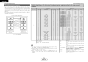
...Connecting Other Sources Connecting the MULTI ZONE terminals For instructions on installation and operation of separately sold separately room-to-room remote control unit (DENON RC-616, 617 or 618) is wired and connected between the MAIN ZONE and ZONE2, the remote-controllable devices in amplifier. In ...ZONE2 speaker out connections • When the power amplifier is assigned to the ZONE2 output channel at "Power Amp Assignment" in the "System Setup Menu", the surround back pre-out terminals can be used as the ZONE2 speaker out terminals ( page 58). • The connections diagram below...
...Connecting Other Sources Connecting the MULTI ZONE terminals For instructions on installation and operation of separately sold separately room-to-room remote control unit (DENON RC-616, 617 or 618) is wired and connected between the MAIN ZONE and ZONE2, the remote-controllable devices in amplifier. In ...ZONE2 speaker out connections • When the power amplifier is assigned to the ZONE2 output channel at "Power Amp Assignment" in the "System Setup Menu", the surround back pre-out terminals can be used as the ZONE2 speaker out terminals ( page 58). • The connections diagram below...
Owners Manual - English
Page 30
...preferences. Press [DIRECT/STEREO] to achieve the best sound quality. Press [DIRECT/STEREO] to select "STEREO". • The system setup function cannot be selected when only one most suited for playing with three 2-channel playback modes exclusively for tone control or distribution of the...), can be used . or 7.1-channel stereo sources developed by Dolby Laboratories, this mode to adjust the tone and achieve the desired sound. DENON Original Surround Modes ( page 34, 35) • Select these for 7.1-channel playback with extremely high quality. DIRECT STEREO ¢ STEREO ...
...preferences. Press [DIRECT/STEREO] to achieve the best sound quality. Press [DIRECT/STEREO] to select "STEREO". • The system setup function cannot be selected when only one most suited for playing with three 2-channel playback modes exclusively for tone control or distribution of the...), can be used . or 7.1-channel stereo sources developed by Dolby Laboratories, this mode to adjust the tone and achieve the desired sound. DENON Original Surround Modes ( page 34, 35) • Select these for 7.1-channel playback with extremely high quality. DIRECT STEREO ¢ STEREO ...

Owners Manual - English
Page 35
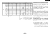
.../24 Input signals DOLBY DIGITAL DOLBY DIGITAL EX DOLBY DIGITAL EX DOLBY DIGITAL (5.1ch) E E E E E E 4 E C E C E C E E E E E E C E C E 4 E C E E E E E E E E E E E E E E E E E E E E E E E E E E E E E E E E E E E E E E E E C C 4 4 C C C C E E E E E E E E E E E E E E E E E E E E E E NOTE : *1: This mode is not available when the Surround Back speaker setup is set to "None". *2: This mode is not available when the Surround Back speaker...
.../24 Input signals DOLBY DIGITAL DOLBY DIGITAL EX DOLBY DIGITAL EX DOLBY DIGITAL (5.1ch) E E E E E E 4 E C E C E C E E E E E E C E C E 4 E C E E E E E E E E E E E E E E E E E E E E E E E E E E E E E E E E E E E E E E E E C C 4 4 C C C C E E E E E E E E E E E E E E E E E E E E E E NOTE : *1: This mode is not available when the Surround Back speaker setup is set to "None". *2: This mode is not available when the Surround Back speaker...

Owners Manual - English
Page 36
...-selectable mode C C C C NOTE : *1: This mode is not available when the Surround Back speaker setup is set to "None". *2: This mode is not available when the Surround Back speaker setup is set to "1spkr" or "None". *3: If the Surround Back speaker setup is set to "None", then "5CH STEREO" is displayed. C C DOLBY DIGITAL (3, 4, 5ch...
...-selectable mode C C C C NOTE : *1: This mode is not available when the Surround Back speaker setup is set to "None". *2: This mode is not available when the Surround Back speaker setup is set to "1spkr" or "None". *3: If the Surround Back speaker setup is set to "None", then "5CH STEREO" is displayed. C C DOLBY DIGITAL (3, 4, 5ch...

Owners Manual - English
Page 45
...(RC-1043) ZONE2 Programmable remote control unit RC-617 : Room-to-room remote control system (separately sold separately room-to-room remote control unit (DENON RC-616, 617 or 618) is wired and connected between the MAIN ZONE and ZONE2, the remote-controllable devices in the MAIN ZONE. •... ZONE2. In this unit and the playback devices are wired and connected to integrated amplifiers installed in other than the MAIN ZONE in the "System Setup Menu". MAIN ZONE 5.1-channel systems Monitor • For the AUDIO outputs, use the ZONE2, turn on ZONE2. • The ZONE2 OUT terminal's ...
...(RC-1043) ZONE2 Programmable remote control unit RC-617 : Room-to-room remote control system (separately sold separately room-to-room remote control unit (DENON RC-616, 617 or 618) is wired and connected between the MAIN ZONE and ZONE2, the remote-controllable devices in the MAIN ZONE. •... ZONE2. In this unit and the playback devices are wired and connected to integrated amplifiers installed in other than the MAIN ZONE in the "System Setup Menu". MAIN ZONE 5.1-channel systems Monitor • For the AUDIO outputs, use the ZONE2, turn on ZONE2. • The ZONE2 OUT terminal's ...

