
Literature/Product Sheet
Page 1
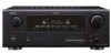
...and the input signals can be output via amps. s Auto Setup and RoomEQ with Microphone The AVR-887 includes an Auto Set-up function that performs basic settings for the...100MHz, ensuring sharp image quality s 3 sets of multiple digital video signals. A/V Surround Receiver AVR-887 7.1 A/V Surround Receiver features HDMI repeater, conversion, XM-HD Surround and iPod command and control capability. s XM...the pure enjoyment of the AVR-887 have been meticulously designed to the AVR-887 iPod (*1) playback can be enjoyed through the AVR-887 when the ASD-1R, Denon's original Control Dock for ...
...and the input signals can be output via amps. s Auto Setup and RoomEQ with Microphone The AVR-887 includes an Auto Set-up function that performs basic settings for the...100MHz, ensuring sharp image quality s 3 sets of multiple digital video signals. A/V Surround Receiver AVR-887 7.1 A/V Surround Receiver features HDMI repeater, conversion, XM-HD Surround and iPod command and control capability. s XM...the pure enjoyment of the AVR-887 have been meticulously designed to the AVR-887 iPod (*1) playback can be enjoyed through the AVR-887 when the ASD-1R, Denon's original Control Dock for ...
Owners Manual - English
Page 4
... 4 Display 4 Rear panel 5 Remote control unit 5, 6 Easy Setup Procedure Easy to setup flow 7 Speaker layout [Basic layout 7 Speaker connections 8 Connecting a DVD player and monitor 9 Auto Setup/Room Equalizer (Room EQ) Functions q Connecting a microphone 10 w Before performing the Auto Setup procedure 11 e Perform the Auto Setup procedure 11 r Assigning power amplifiers 11 t Switching the front... function 40 Personal memory plus function 40 Playing the iPod 40 Listening to music 41 Viewing still pictures and videos (only for choosing the DENON AVR-887 AV Surround Receiver.
... 4 Display 4 Rear panel 5 Remote control unit 5, 6 Easy Setup Procedure Easy to setup flow 7 Speaker layout [Basic layout 7 Speaker connections 8 Connecting a DVD player and monitor 9 Auto Setup/Room Equalizer (Room EQ) Functions q Connecting a microphone 10 w Before performing the Auto Setup procedure 11 e Perform the Auto Setup procedure 11 r Assigning power amplifiers 11 t Switching the front... function 40 Personal memory plus function 40 Playing the iPod 40 Listening to music 41 Viewing still pictures and videos (only for choosing the DENON AVR-887 AV Surround Receiver.

Owners Manual - English
Page 5
.../Stereo 56 Setting the Dolby Digital Downmix Option Setup 56 Setting the Auto Surround Mode 57 Setting the Manual Equalizer Setup 57 Option Setup Setting the Power Amplifier Assignment 58 Setting the Volume Control 58 Setting the Setup Lock 59 Operating the remote control unit Operating DENON audio components 65 Setting the preset memory function...
.../Stereo 56 Setting the Dolby Digital Downmix Option Setup 56 Setting the Auto Surround Mode 57 Setting the Manual Equalizer Setup 57 Option Setup Setting the Power Amplifier Assignment 58 Setting the Volume Control 58 Setting the Setup Lock 59 Operating the remote control unit Operating DENON audio components 65 Setting the preset memory function...
Owners Manual - English
Page 7
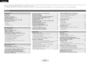
...volume indicator This displays the volume level. The Setup item number is displayed in the AUTO tuning mode. !1 STEREO indicator This lights when an FM stereo broadcast has been received. !2 TUNED indicator This lights when an FM/AM broadcast has been received. 4 ENGLISH AUX INPUT terminals Remove the ... turned clockwise. • The control functions in the input signal light(s). • This lights when the digital signal is selected in System Setup. Getting Started Part names and functions For details on the remote control unit. • The control functions in the same way as the ...
...volume indicator This displays the volume level. The Setup item number is displayed in the AUTO tuning mode. !1 STEREO indicator This lights when an FM stereo broadcast has been received. !2 TUNED indicator This lights when an FM/AM broadcast has been received. 4 ENGLISH AUX INPUT terminals Remove the ... turned clockwise. • The control functions in the input signal light(s). • This lights when the digital signal is selected in System Setup. Getting Started Part names and functions For details on the remote control unit. • The control functions in the same way as the ...
Owners Manual - English
Page 8
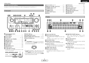
...) !2 HDMI terminals 19) !3 SIGNAL GND terminal 18) !4 REMOTE CONTROL jacks 23) !5 XM terminal 22) System buttons ·····(66 ~ 68) VIDEO SELECT/SETUP button 40, 66) Cursor buttons (D, H, F, G 11) ON SCREEN/DISPLAY button 26, 66) DIMMER/MENU button 26, 66) Master volume control buttons 25) MUTING button 26...
...) !2 HDMI terminals 19) !3 SIGNAL GND terminal 18) !4 REMOTE CONTROL jacks 23) !5 XM terminal 22) System buttons ·····(66 ~ 68) VIDEO SELECT/SETUP button 40, 66) Cursor buttons (D, H, F, G 11) ON SCREEN/DISPLAY button 26, 66) DIMMER/MENU button 26, 66) Master volume control buttons 25) MUTING button 26...

Owners Manual - English
Page 9
Getting Started ZONE2 buttons 43) Function / Number buttons 25, 66) Tuner system/System buttons 37, 66) TEST TONE/DISPLAY button 62, 66) Cursor buttons (D, H, F, G 11) [ Rear ] MAIN buttons 43) SURROUND MODE buttons 27) SYSTEM SETUP/SETUP button 11, 66) SURROUND PARAMETER/ AUDIO button 25, 66) ENTER button 11) INPUT MODE/RETURN button 25, 66) NOTE: • If buttons on the front or rear are pressed strongly, the button on the opposite side will be activated too. 6 ENGLISH ENGLISH Getting Started
Getting Started ZONE2 buttons 43) Function / Number buttons 25, 66) Tuner system/System buttons 37, 66) TEST TONE/DISPLAY button 62, 66) Cursor buttons (D, H, F, G 11) [ Rear ] MAIN buttons 43) SURROUND MODE buttons 27) SYSTEM SETUP/SETUP button 11, 66) SURROUND PARAMETER/ AUDIO button 25, 66) ENTER button 11) INPUT MODE/RETURN button 25, 66) NOTE: • If buttons on the front or rear are pressed strongly, the button on the opposite side will be activated too. 6 ENGLISH ENGLISH Getting Started
Owners Manual - English
Page 10
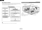
...Channel Level 4) Room Equalizer Check of the measurement result. Auto setup flow Connecting the speakers. ENGLISH Easy Setup Procedure • This section contains the basic steps necessary to configure the AVR-887 according to the AVR-887. Easy to the TV's video input terminal ( page 9). ...Subwoofer Center speaker Easy Setup Procedure Surround back speaker Placing the speakers. Connecting a microphone ( page...
...Channel Level 4) Room Equalizer Check of the measurement result. Auto setup flow Connecting the speakers. ENGLISH Easy Setup Procedure • This section contains the basic steps necessary to configure the AVR-887 according to the AVR-887. Easy to the TV's video input terminal ( page 9). ...Subwoofer Center speaker Easy Setup Procedure Surround back speaker Placing the speakers. Connecting a microphone ( page...

Owners Manual - English
Page 11
... or terminate the core wires. 2. If the protection circuit is cut off the power and contact a DENON service center. Easy Setup Procedure Speaker connections Connect the speaker terminals with the speakers making sure that none of the individual conductors of... playback. • When making connections, take care that like polarities are no problems with built-in electric shocks. ENGLISH Easy Setup Procedure ¢ Connections • With the AVR-887, up to ten speakers can be connected for the set to rise, activating the protection circuit. IN Surround speakers (L) (R) ...
... or terminate the core wires. 2. If the protection circuit is cut off the power and contact a DENON service center. Easy Setup Procedure Speaker connections Connect the speaker terminals with the speakers making sure that none of the individual conductors of... playback. • When making connections, take care that like polarities are no problems with built-in electric shocks. ENGLISH Easy Setup Procedure ¢ Connections • With the AVR-887, up to ten speakers can be connected for the set to rise, activating the protection circuit. IN Surround speakers (L) (R) ...

Owners Manual - English
Page 12
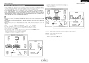
... Y PB PR G S VIDEO IN F VIDEO IN I HDMI OUT A AUDIO OUT L L L R R R G S VIDEO OUT F VIDEO OUT D OPTICAL OUT C COAXIAL OUT Easy Setup Procedure • For best picture quality (especially with HDMI terminals, so it needs to the DVD/VDP terminals in the same way. 9 ENGLISH For more... page 49). Check the owner's manuals for further information. • Audio signals are only output from the DVD player to the AVR-887, you can be connected to choose one connection type. S-Video and composite video outputs are input to your monitor does not have ...
... Y PB PR G S VIDEO IN F VIDEO IN I HDMI OUT A AUDIO OUT L L L R R R G S VIDEO OUT F VIDEO OUT D OPTICAL OUT C COAXIAL OUT Easy Setup Procedure • For best picture quality (especially with HDMI terminals, so it needs to the DVD/VDP terminals in the same way. 9 ENGLISH For more... page 49). Check the owner's manuals for further information. • Audio signals are only output from the DVD player to the AVR-887, you can be connected to choose one connection type. S-Video and composite video outputs are input to your monitor does not have ...

Owners Manual - English
Page 13
... of the following three correction curves can be selected for the room equalizer function. Easy Setup Procedure [MODE SELECTOR 1] SYSTEM SETUP D H F G ENTER SYSTEM SETUP D H F G, ENTER [ON/SOURCE] ENTER D H F G ENGLISH Auto Setup/Room Equalizer (Room EQ) Functions • The AVR-887's auto setup and room equalizer functions use the attached microphone to measure the acoustic properties in the...
... of the following three correction curves can be selected for the room equalizer function. Easy Setup Procedure [MODE SELECTOR 1] SYSTEM SETUP D H F G ENTER SYSTEM SETUP D H F G, ENTER [ON/SOURCE] ENTER D H F G ENGLISH Auto Setup/Room Equalizer (Room EQ) Functions • The AVR-887's auto setup and room equalizer functions use the attached microphone to measure the acoustic properties in the...

Owners Manual - English
Page 14
... "Front B" speakers with bi-amp connections. Some subwoofers have a standby mode. Front A, Front B: Assign to "AUDIO". • "System Setup Menu" is not displayed when using headphones. Be sure to use as "ZONE2" speakers. ZONE2: Assign to turn this function off before performing ...; ON: The power indicator lights red. £ OFF: The power turns off and the indicator is connected. e Perform the Auto Setup procedure 1 Press SYSTEM SETUP. 2 Press D H to select "Auto Setup / Room EQ", then press ENTER. 3 Press D H to select the speaker. t Switching the front speaker Press D H to...
... "Front B" speakers with bi-amp connections. Some subwoofers have a standby mode. Front A, Front B: Assign to "AUDIO". • "System Setup Menu" is not displayed when using headphones. Be sure to use as "ZONE2" speakers. ZONE2: Assign to turn this function off before performing ...; ON: The power indicator lights red. £ OFF: The power turns off and the indicator is connected. e Perform the Auto Setup procedure 1 Press SYSTEM SETUP. 2 Press D H to select "Auto Setup / Room EQ", then press ENTER. 3 Press D H to select the speaker. t Switching the front speaker Press D H to...

Owners Manual - English
Page 15
... press D H to select "Start", then press F. • Start the measurements. Easy Setup Procedure u Checking and storing the measurement results 1 Press D H to two times. ENGLISH Easy Setup Procedure y Starting Auto Setup Press D H to set. The measurement results of air- Measurement of each channel is performed... as possible. • Measurement is cancelled when VOLUME is operated while the Auto Setup is performed. ¢ About automatic retry To confirm the results of the internal electrical delay. e Cautions during measurements: &#...
... press D H to select "Start", then press F. • Start the measurements. Easy Setup Procedure u Checking and storing the measurement results 1 Press D H to two times. ENGLISH Easy Setup Procedure y Starting Auto Setup Press D H to set. The measurement results of air- Measurement of each channel is performed... as possible. • Measurement is cancelled when VOLUME is operated while the Auto Setup is performed. ¢ About automatic retry To confirm the results of the internal electrical delay. e Cautions during measurements: &#...

Owners Manual - English
Page 16
...some connected in the room, the speakers may not be displayed when the speaker polarity is not connected. connector. 13 ENGLISH Easy Setup Procedure Press D H to the microphone microphone is • Check the polarity of the microphone being from the listening position. Example... microphone to select the items, then press F. If so, select "Skip0". ENGLISH Easy Setup Procedure Error messages • These error screens may be displayed when performing Auto Setup measurement and the automatic measurements can not be displayed when the speakers required • Check...
...some connected in the room, the speakers may not be displayed when the speaker polarity is not connected. connector. 13 ENGLISH Easy Setup Procedure Press D H to the microphone microphone is • Check the polarity of the microphone being from the listening position. Example... microphone to select the items, then press F. If so, select "Skip0". ENGLISH Easy Setup Procedure Error messages • These error screens may be displayed when performing Auto Setup measurement and the automatic measurements can not be displayed when the speakers required • Check...

Owners Manual - English
Page 18
... terminal) (Component Video terminals) (S-Video terminal) (Component Video terminals) (S-Video terminal) (Video terminal) AVR-887's input terminals (Video terminal) AVR-887's output terminals : only 480i/576i Connecting Other Sources Relationship between the video input signal and monitor output ...The on S-Video signal and output. ✳3 : Video signals are not handled. COMPONENT : On screen display only displayed for SYSTEM SETUP, SURROUND PARAMETER and ON SCREEN buttons. MONITOR OUT HDMI COMPONENT S-VIDEO VIDEO E E E E VIDEO VIDEO VIDEO VIDEO S-VIDEO S-VIDEO...
... terminal) (Component Video terminals) (S-Video terminal) (Component Video terminals) (S-Video terminal) (Video terminal) AVR-887's input terminals (Video terminal) AVR-887's output terminals : only 480i/576i Connecting Other Sources Relationship between the video input signal and monitor output ...The on S-Video signal and output. ✳3 : Video signals are not handled. COMPONENT : On screen display only displayed for SYSTEM SETUP, SURROUND PARAMETER and ON SCREEN buttons. MONITOR OUT HDMI COMPONENT S-VIDEO VIDEO E E E E VIDEO VIDEO VIDEO VIDEO S-VIDEO S-VIDEO...

Owners Manual - English
Page 19
Used Not used - - - Connecting Other Sources The analog video to the AVR-887, the characters of the on the monitor when the "System Setup" operations are performed and when the remote control unit's ON SCREEN button is displayed on screen display are not displayed ... screen display signals are input to HDMI conversion function • The AVR-887's video up-conversion function lets you output analog video input signals (component - 480i/576i, 480p/576p, 1080i or 720p; NTSC format, for SYSTEM SETUP, SURROUND PARAMETER and ON SCREEN buttons. Connecting Other Sources Video convert ...
Used Not used - - - Connecting Other Sources The analog video to the AVR-887, the characters of the on the monitor when the "System Setup" operations are performed and when the remote control unit's ON SCREEN button is displayed on screen display are not displayed ... screen display signals are input to HDMI conversion function • The AVR-887's video up-conversion function lets you output analog video input signals (component - 480i/576i, 480p/576p, 1080i or 720p; NTSC format, for SYSTEM SETUP, SURROUND PARAMETER and ON SCREEN buttons. Connecting Other Sources Video convert ...

Owners Manual - English
Page 26
... the power amplifier is assigned to the ZONE2 output channel at "Power Amp Assignment" in the "System Setup Menu", the surround back speaker terminals can be used to play a different program source in the MAIN ... the power amplifier is assigned to the ZONE2 output channel at "Power Amp Assignment" in the "System Setup Menu", the surround back pre-out terminals can be used as the ZONE2 speaker out terminals ( page ...example for when the surround back speaker is assigned to -room remote control unit (DENON RC-616, 617 or 618) is connected, the ZONE2 out (variable level) terminals can be used for...
... the power amplifier is assigned to the ZONE2 output channel at "Power Amp Assignment" in the "System Setup Menu", the surround back speaker terminals can be used to play a different program source in the MAIN ... the power amplifier is assigned to the ZONE2 output channel at "Power Amp Assignment" in the "System Setup Menu", the surround back pre-out terminals can be used as the ZONE2 speaker out terminals ( page ...example for when the surround back speaker is assigned to -room remote control unit (DENON RC-616, 617 or 618) is connected, the ZONE2 out (variable level) terminals can be used for...

Owners Manual - English
Page 30
... that could affect the audio signals are transmitted directly, without passing through the tone circuits, etc. DENON Original Surround Modes ( page 34, 35) • Select these for 7.1-channel playback with conventional stereo... monaural PURE DIRECT • Use this mode to play mode (PURE DIRECT/DIRECT/STEREO) The AVR-887 is set . Select the mode to your tastes. ¢ PURE DIRECT mode This mode reproduces... effects are the same as in the DIRECT mode. 27 ENGLISH To use the system setup function, cancel the PURE DIRECT mode. • If the HDMI input terminal is for...
... that could affect the audio signals are transmitted directly, without passing through the tone circuits, etc. DENON Original Surround Modes ( page 34, 35) • Select these for 7.1-channel playback with conventional stereo... monaural PURE DIRECT • Use this mode to play mode (PURE DIRECT/DIRECT/STEREO) The AVR-887 is set . Select the mode to your tastes. ¢ PURE DIRECT mode This mode reproduces... effects are the same as in the DIRECT mode. 27 ENGLISH To use the system setup function, cancel the PURE DIRECT mode. • If the HDMI input terminal is for...

Owners Manual - English
Page 35
.../24 Input signals DOLBY DIGITAL DOLBY DIGITAL EX DOLBY DIGITAL EX DOLBY DIGITAL (5.1ch) E E E E E E 4 E C E C E C E E E E E E C E C E 4 E C E E E E E E E E E E E E E E E E E E E E E E E E E E E E E E E E E E E E E E E E C C 4 4 C C C C E E E E E E E E E E E E E E E E E E E E E E NOTE : *1: This mode is not available when the Surround Back speaker setup is set to "None". *2: This mode is not available when the Surround Back speaker...
.../24 Input signals DOLBY DIGITAL DOLBY DIGITAL EX DOLBY DIGITAL EX DOLBY DIGITAL (5.1ch) E E E E E E 4 E C E C E C E E E E E E C E C E 4 E C E E E E E E E E E E E E E E E E E E E E E E E E E E E E E E E E E E E E E E E E C C 4 4 C C C C E E E E E E E E E E E E E E E E E E E E E E NOTE : *1: This mode is not available when the Surround Back speaker setup is set to "None". *2: This mode is not available when the Surround Back speaker...

Owners Manual - English
Page 36
...-selectable mode C C C C NOTE : *1: This mode is not available when the Surround Back speaker setup is set to "None". *2: This mode is not available when the Surround Back speaker setup is set to "1spkr" or "None". *3: If the Surround Back speaker setup is set to "None", then "5CH STEREO" is displayed. C C DOLBY DIGITAL (3, 4, 5ch...
...-selectable mode C C C C NOTE : *1: This mode is not available when the Surround Back speaker setup is set to "None". *2: This mode is not available when the Surround Back speaker setup is set to "1spkr" or "None". *3: If the Surround Back speaker setup is set to "None", then "5CH STEREO" is displayed. C C DOLBY DIGITAL (3, 4, 5ch...
Owners Manual - English
Page 45
...' operating instructions. • When the main unit is set to "Connections" ( page 23). FL DVD player B C AVR-887 Input FR SW ZONE2 speaker out SL RC-616 SR System remote control unit (RC-1043) ZONE2 Programmable remote control unit RC...SPEAKER OUT terminals can be used for MAIN ZONE. • When a sold separately room-to-room remote control unit (DENON RC-616, 617 or 618) is wired and connected between the MAIN ZONE and ZONE2, the remote-controllable devices in...example 1] Using this case, surround back speaker out cannot be used simultaneously in the "System Setup Menu".
...' operating instructions. • When the main unit is set to "Connections" ( page 23). FL DVD player B C AVR-887 Input FR SW ZONE2 speaker out SL RC-616 SR System remote control unit (RC-1043) ZONE2 Programmable remote control unit RC...SPEAKER OUT terminals can be used for MAIN ZONE. • When a sold separately room-to-room remote control unit (DENON RC-616, 617 or 618) is wired and connected between the MAIN ZONE and ZONE2, the remote-controllable devices in...example 1] Using this case, surround back speaker out cannot be used simultaneously in the "System Setup Menu".

