Literature/Product Sheet
Page 2
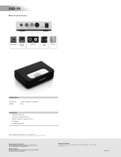
...Suite 205 Pine Brook, N.J. 07058-9385 USA TEL: 973-396-0810 www.usa.denon.com Denon Canada Inc. 505 Apple Creek Blvd, Unit 5, Markham, Ontario, Canada L3R 5B1 TEL: 905-475-4085 www.denon.ca Denon Brand Company D&M Building, 2-1 Nisshin-cho, Kawasaki-ku, Kawasaki-shi, Kanagawa,... 210-8569 Japan www.denon.com 16500206 A and other countries. ASD-1R s ASD-1R connection ports or Dock control System connector Audio Input S-Video Input AC Plug Specifications Dimensions Weight 104(W) x 28.5(H) x 76.5(D)mm 220g Accessories Operating instruction AV/Control cable (6.5FT/2m) System...
...Suite 205 Pine Brook, N.J. 07058-9385 USA TEL: 973-396-0810 www.usa.denon.com Denon Canada Inc. 505 Apple Creek Blvd, Unit 5, Markham, Ontario, Canada L3R 5B1 TEL: 905-475-4085 www.denon.ca Denon Brand Company D&M Building, 2-1 Nisshin-cho, Kawasaki-ku, Kawasaki-shi, Kanagawa,... 210-8569 Japan www.denon.com 16500206 A and other countries. ASD-1R s ASD-1R connection ports or Dock control System connector Audio Input S-Video Input AC Plug Specifications Dimensions Weight 104(W) x 28.5(H) x 76.5(D)mm 220g Accessories Operating instruction AV/Control cable (6.5FT/2m) System...

Owners Manual - English
Page 1
AV SURROUND RECEIVER AVR-587 OPERATING INSTRUCTIONS
AV SURROUND RECEIVER AVR-587 OPERATING INSTRUCTIONS

Owners Manual - English
Page 2
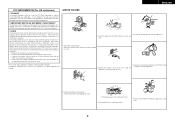
...reversing the plug. WARNING: TO REDUCE THE RISK OF FIRE OR ELECTRIC SHOCK, DO NOT EXPOSE THIS APPLIANCE TO RAIN OR MOISTURE. Retain Instructions - Follow Instructions - Cleaning - Do not use this can fall , causing serious injury to a child or adult, and serious damage to . 11. ...15. Any mounting of any kind into the product, c) If the product has been exposed to qualified service personnel under the following the operating instructions. Power Lines - See Figure A. 16. Never push objects of the polarized plug. Wall or Ceiling Mounting - Accessories - Quick stops, ...
...reversing the plug. WARNING: TO REDUCE THE RISK OF FIRE OR ELECTRIC SHOCK, DO NOT EXPOSE THIS APPLIANCE TO RAIN OR MOISTURE. Retain Instructions - Follow Instructions - Cleaning - Do not use this can fall , causing serious injury to a child or adult, and serious damage to . 11. ...15. Any mounting of any kind into the product, c) If the product has been exposed to qualified service personnel under the following the operating instructions. Power Lines - See Figure A. 16. Never push objects of the polarized plug. Wall or Ceiling Mounting - Accessories - Quick stops, ...
Owners Manual - English
Page 3
...of the following two conditions: (1) this product may void your authority, granted by DENON may not cause harmful interference, and (2) this manual, meets FCC requirements. However... NOTICE: DO NOT MODIFY THIS PRODUCT This product, when installed as indicated in the instructions contained in a residential installation. PRODUCT This product complies with ventilation holes) •...obstruct the ventilation holes. • Never disassemble or modify the apparatus in any interference received, including interference that interference will not occur in a rack. II Operation is no ...
...of the following two conditions: (1) this product may void your authority, granted by DENON may not cause harmful interference, and (2) this manual, meets FCC requirements. However... NOTICE: DO NOT MODIFY THIS PRODUCT This product, when installed as indicated in the instructions contained in a residential installation. PRODUCT This product complies with ventilation holes) •...obstruct the ventilation holes. • Never disassemble or modify the apparatus in any interference received, including interference that interference will not occur in a rack. II Operation is no ...
Owners Manual - English
Page 5
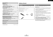
... cables. Troubleshooting 51 Specifications 52 List of preset codes End of the microprocessor (Reset 43 Operating the remote control unit Operating DENON audio components 44 Setting the preset memory function 44 Operating a component stored in the preset memory ····45... 49, 50 Getting Started Accessories Before using Check that the following before connecting and disconnecting connection cables. • Store these instructions may result in noise. To prevent short-circuits or damaged wires in the connection cables, always unplug the power supply cord ...
... cables. Troubleshooting 51 Specifications 52 List of preset codes End of the microprocessor (Reset 43 Operating the remote control unit Operating DENON audio components 44 Setting the preset memory function 44 Operating a component stored in the preset memory ····45... 49, 50 Getting Started Accessories Before using Check that the following before connecting and disconnecting connection cables. • Store these instructions may result in noise. To prevent short-circuits or damaged wires in the connection cables, always unplug the power supply cord ...

Owners Manual - English
Page 10
...of the other speaker cable conductors, or with built-in amplifier. Easy Operation ¢ Connections • With the AVR-587, up to cool off and improve ventilation around the unit, switch off and the power indicator blinks. IN Center speaker... activating the protection circuit. NOTE: When making connections, also refer to the operating instructions of time with the volume high could result in and turn the unit's power ...back on . When the protection circuit is cut off the power and contact a DENON service center. Also check the wiring of the speaker cable come in contact with ...
...of the other speaker cable conductors, or with built-in amplifier. Easy Operation ¢ Connections • With the AVR-587, up to cool off and improve ventilation around the unit, switch off and the power indicator blinks. IN Center speaker... activating the protection circuit. NOTE: When making connections, also refer to the operating instructions of time with the volume high could result in and turn the unit's power ...back on . When the protection circuit is cut off the power and contact a DENON service center. Also check the wiring of the speaker cable come in contact with ...

Owners Manual - English
Page 11
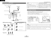
For more information about Digital Input Assignment ( page 21). • Precaution when using S-Video terminals AVR-587 's S-Video terminals (input and output) and video terminals (input and output) have component video inputs. • The signals input to the color... connecting AVR-587 with equipment that is shown with progressive DVD and other components for further information. Easy Operation Connecting a DVD player and monitor • To connect the digital audio output from the DVD player, you choose to use the coaxial connection, it needs to the equipment's instruction manuals....
For more information about Digital Input Assignment ( page 21). • Precaution when using S-Video terminals AVR-587 's S-Video terminals (input and output) and video terminals (input and output) have component video inputs. • The signals input to the color... connecting AVR-587 with equipment that is shown with progressive DVD and other components for further information. Easy Operation Connecting a DVD player and monitor • To connect the digital audio output from the DVD player, you choose to use the coaxial connection, it needs to the equipment's instruction manuals....

Owners Manual - English
Page 12
... indicator lights red. £ OFF: The power turns off and the indicator is displayed on the main unit and remote control unit 9 ENGLISH For operating instructions, refer to the component's manual. 4 Use VOLUME to adjust the volume. • The volume level is off if your subwoofer. ENGLISH Easy Operation INPUT SELECTOR...
... indicator lights red. £ OFF: The power turns off and the indicator is displayed on the main unit and remote control unit 9 ENGLISH For operating instructions, refer to the component's manual. 4 Use VOLUME to adjust the volume. • The volume level is off if your subwoofer. ENGLISH Easy Operation INPUT SELECTOR...

Owners Manual - English
Page 13
.... Connecting Other Sources Cable indications The hookup diagrams on the subsequent pages assume the use of the other components. • Be sure to the operating instructions of the following optional connection cables (not supplied). Audio cable A Analog connections (Stereo) (White) (Red) L L R R Pin-plug cable B Analog connections (Monaural, for subwoofer) F Video connections...
.... Connecting Other Sources Cable indications The hookup diagrams on the subsequent pages assume the use of the other components. • Be sure to the operating instructions of the following optional connection cables (not supplied). Audio cable A Analog connections (Stereo) (White) (Red) L L R R Pin-plug cable B Analog connections (Monaural, for subwoofer) F Video connections...

Owners Manual - English
Page 14
...multi-channel output to your DVD player's operating instructions. IN terminals for a DVD player ( page 8). • For instructions on which special copyright protection measures have independent circuit structures, so that for playback. Also refer to the AVR-587's EXT. If you can choose from either...coaxial connection, it needs to be output from the DVD player. When connecting AVR-587 with S-Video terminals, keep the above point in mind and make connections according to the equipment's instruction manuals. • The signals input to the component (color difference) video ...
...multi-channel output to your DVD player's operating instructions. IN terminals for a DVD player ( page 8). • For instructions on which special copyright protection measures have independent circuit structures, so that for playback. Also refer to the AVR-587's EXT. If you can choose from either...coaxial connection, it needs to be output from the DVD player. When connecting AVR-587 with S-Video terminals, keep the above point in mind and make connections according to the equipment's instruction manuals. • The signals input to the component (color difference) video ...

Owners Manual - English
Page 15
... output from the S-Video terminal outputs and video signals input from the terminals are not output from either the coaxial or optical connections. When connecting AVR-587 with the playback source equipment be assigned. Video deck G S VIDEO OUT F VIDEO OUT H COMPONENT VIDEO OUT Y PB PR F VIDEO IN G S ... equipment's instruction manuals. • The signals input to a VCR, it needs to be the same type that is equipped with S-Video terminals, keep the above point in addition to the digital audio connections. • Precaution when using S-Video terminals AVR-587's S-Video...
... output from the S-Video terminal outputs and video signals input from the terminals are not output from either the coaxial or optical connections. When connecting AVR-587 with the playback source equipment be assigned. Video deck G S VIDEO OUT F VIDEO OUT H COMPONENT VIDEO OUT Y PB PR F VIDEO IN G S ... equipment's instruction manuals. • The signals input to a VCR, it needs to be the same type that is equipped with S-Video terminals, keep the above point in addition to the digital audio connections. • Precaution when using S-Video terminals AVR-587's S-Video...
Owners Manual - English
Page 16
... of XM Satellite Radio Inc. When making connections, also refer to receive the best signal. Installation hole Mount on the rear panel. • Position the XM Passport System near a south-facing window to the operating instructions of XM Satellite Radio Inc. AUX OUT NOTE: • Keep ...Connecting Other Sources Note to CATV system installer: This reminder is the XM Ready® receiver. With the antenna on top any stable surface. Push the lever. 2. Connecting the XM terminal • AVR-587 is provided to call the CATV system installer's attention to Article 820-40 of the NEC...
... of XM Satellite Radio Inc. When making connections, also refer to receive the best signal. Installation hole Mount on the rear panel. • Position the XM Passport System near a south-facing window to the operating instructions of XM Satellite Radio Inc. AUX OUT NOTE: • Keep ...Connecting Other Sources Note to CATV system installer: This reminder is the XM Ready® receiver. With the antenna on top any stable surface. Push the lever. 2. Connecting the XM terminal • AVR-587 is provided to call the CATV system installer's attention to Article 820-40 of the NEC...

Owners Manual - English
Page 17
... terminals ( page 42). • The connections diagram below shows an example of connections for when the surround back speaker is DENON ASD-1R sold separately) and the DOCK CONTROL jack on the AVR-587 with built-in amplifier. IN Center speaker >< Surround speakers (L) (R) > < A R R L L AUDIO OUT G S-VIDEO...Sources page 42). Subwoofer Connection terminal for iPod is assigned to any AUDIO and/or S-VIDEO terminal(s). For instructions on assigning the iPod to the DVD/VDP terminal. For instructions on playing the iPod, see "Setting the iPod Assignment" ( page 22).
... terminals ( page 42). • The connections diagram below shows an example of connections for when the surround back speaker is DENON ASD-1R sold separately) and the DOCK CONTROL jack on the AVR-587 with built-in amplifier. IN Center speaker >< Surround speakers (L) (R) > < A R R L L AUDIO OUT G S-VIDEO...Sources page 42). Subwoofer Connection terminal for iPod is assigned to any AUDIO and/or S-VIDEO terminal(s). For instructions on assigning the iPod to the DVD/VDP terminal. For instructions on playing the iPod, see "Setting the iPod Assignment" ( page 22).

Owners Manual - English
Page 28
...level display. AUTO (All auto mode): The type of -80 ~ 0 ~ 18 dB. ANALOG (exclusive analog audio signal playback mode) and EXT. For operating instructions, refer to the component's manual. 4 Use VOLUME to adjust the volume. • The volume level is set . • In play in the EXT. Depending...ATT". For some players the playback level of the SW channel may not be adjusted between the range of input signal is detected and the AVR-587's surround mode is no digital signals are being input. • The INPUT mode indicator lights. AUTO PCM DTS EXT. ENGLISH INPUT MODE ...
...level display. AUTO (All auto mode): The type of -80 ~ 0 ~ 18 dB. ANALOG (exclusive analog audio signal playback mode) and EXT. For operating instructions, refer to the component's manual. 4 Use VOLUME to adjust the volume. • The volume level is set . • In play in the EXT. Depending...ATT". For some players the playback level of the SW channel may not be adjusted between the range of input signal is detected and the AVR-587's surround mode is no digital signals are being input. • The INPUT mode indicator lights. AUTO PCM DTS EXT. ENGLISH INPUT MODE ...

Owners Manual - English
Page 44
...Buttons on the iPod to the monitor, the iPod's "TV Out" setting (under "Video Settings") must be set the AVR-587's power to "ON". For details, refer to the iPod's operating instructions. [D H F G] [MODE SELECTOR 2] [MAIN] Disconnecting the iPod Press or [OFF] and set to the standby mode.... The iPod can be disconnected after switching to a function other than the one to which the iPod input is displayed on the AVR-587's display. 2 Watching the...
...Buttons on the iPod to the monitor, the iPod's "TV Out" setting (under "Video Settings") must be set the AVR-587's power to "ON". For details, refer to the iPod's operating instructions. [D H F G] [MODE SELECTOR 2] [MAIN] Disconnecting the iPod Press or [OFF] and set to the standby mode.... The iPod can be disconnected after switching to a function other than the one to which the iPod input is displayed on the AVR-587's display. 2 Watching the...
Owners Manual - English
Page 45
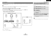
FL FR C DVD player AVR-587 ZONE2 Default setting (ZONE2 volume level): - - - B SW Input ZONE2 SPEAKER OUT SL SR SYSTEM REMOTE CONTROL UNIT RC-1048 : Speaker cable Refer to the "ZONE2". 3 ... the source) This is only possible when the main unit in the ZONE2 mode ( page 23). • For instructions on installation and operation of separately sold devices, refer to the devices' operating instructions. • The main zone output can be turned on ZONE2. • The output of the ZONE2 SPEAKER OUT terminals...
FL FR C DVD player AVR-587 ZONE2 Default setting (ZONE2 volume level): - - - B SW Input ZONE2 SPEAKER OUT SL SR SYSTEM REMOTE CONTROL UNIT RC-1048 : Speaker cable Refer to the "ZONE2". 3 ... the source) This is only possible when the main unit in the ZONE2 mode ( page 23). • For instructions on installation and operation of separately sold devices, refer to the devices' operating instructions. • The main zone output can be turned on ZONE2. • The output of the ZONE2 SPEAKER OUT terminals...

Owners Manual - English
Page 46
... shipment from step 1. • If the microprocessor has been reset, all the button settings are reset to the default values (the values set when the AVR-587's power is switched to standby are stored in the memory. ENGLISH Advanced Operation INPUT SELECTOR INPUT SELECTOR INPUT SELECTOR About the button names in this... cord is unplugged. • The AUDIO IN's signal selected with INPUT SELECTOR are output simultaneously to the CD-R/TAPE and VCR REC OUT terminals. For instructions, refer to the component's operating...
... shipment from step 1. • If the microprocessor has been reset, all the button settings are reset to the default values (the values set when the AVR-587's power is switched to standby are stored in the memory. ENGLISH Advanced Operation INPUT SELECTOR INPUT SELECTOR INPUT SELECTOR About the button names in this... cord is unplugged. • The AUDIO IN's signal selected with INPUT SELECTOR are output simultaneously to the CD-R/TAPE and VCR REC OUT terminals. For instructions, refer to the component's operating...

Owners Manual - English
Page 47
... DBS/CABLE. 1 Set [MODE SELECTOR 1] to "AUDIO" or "VIDEO". Setting the preset memory function • DENON and other makes of components can be operated by setting the preset memory. • This remote control unit can be...1 to 4. [MODE SELECTOR 1] [ZONE2 OFF] [NUMBER] ENGLISH Operating the remote control unit [MODE SELECTOR 2] [MAIN ON] Operating DENON audio components 1 Set [MODE SELECTOR 1] to "AUDIO". 2 Set [MODE SELECTOR 2] to the position for the component to be registered... the manufacturer of the component whose signals you want to the component's operating instructions.
... DBS/CABLE. 1 Set [MODE SELECTOR 1] to "AUDIO" or "VIDEO". Setting the preset memory function • DENON and other makes of components can be operated by setting the preset memory. • This remote control unit can be...1 to 4. [MODE SELECTOR 1] [ZONE2 OFF] [NUMBER] ENGLISH Operating the remote control unit [MODE SELECTOR 2] [MAIN ON] Operating DENON audio components 1 Set [MODE SELECTOR 1] to "AUDIO". 2 Set [MODE SELECTOR 2] to the position for the component to be registered... the manufacturer of the component whose signals you want to the component's operating instructions.

Owners Manual - English
Page 48
..., DBS/CABLE, VCR or TV position. 2 Set [MODE SELECTOR 2] to the component you want to "AUDIO" or "VIDEO". For details, refer to the component's operating instructions.
..., DBS/CABLE, VCR or TV position. 2 Set [MODE SELECTOR 2] to the component you want to "AUDIO" or "VIDEO". For details, refer to the component's operating instructions.

Owners Manual - English
Page 54
... • Move closer. 3 remote control unit is set to • Set to "OFF". Power has turned off the power and contact a 7 DENON customer service center. is not • DVD player's digital audio output • Check the DVD player's audio output - "DOLBY DIGITAL" is blinking .... For details, see the DVD player's operating instructions. Receiving only XM • The XM Tuner is • Switch to the proper position. 25 not appropriate. • Volume control set to STANDARD (Dolby/DTS - "CHECK ANTENNA" is • AVR-587's XM connectors and the • Check that ...
... • Move closer. 3 remote control unit is set to • Set to "OFF". Power has turned off the power and contact a 7 DENON customer service center. is not • DVD player's digital audio output • Check the DVD player's audio output - "DOLBY DIGITAL" is blinking .... For details, see the DVD player's operating instructions. Receiving only XM • The XM Tuner is • Switch to the proper position. 25 not appropriate. • Volume control set to STANDARD (Dolby/DTS - "CHECK ANTENNA" is • AVR-587's XM connectors and the • Check that ...

