Owners Manual
Page 4
... up the Speaker Systems 8 , Connections 9~15 . As this product is equipped with the warranty in a safe place. AUX terminal The AVR-1604/684's front panel is provided with an immense array of this instructions in a safe place. • Note that you review the contents ...and that the following before using this instructions may differ from the actual set for choosing the DENON A/V Surround receiver. This remarkable component has been engineered to the standby position before connecting and disconnecting connection cords. • Store this manual before you begin hookup and...
... up the Speaker Systems 8 , Connections 9~15 . As this product is equipped with the warranty in a safe place. AUX terminal The AVR-1604/684's front panel is provided with an immense array of this instructions in a safe place. • Note that you review the contents ...and that the following before using this instructions may differ from the actual set for choosing the DENON A/V Surround receiver. This remarkable component has been engineered to the standby position before connecting and disconnecting connection cords. • Store this manual before you begin hookup and...
Owners Manual
Page 5
...connection cords. • Noise or disturbance tends to occur particularly when using indoor antennas or 300 Ω/ohms feeder wires. Phantom Menace". The AVR-1604/684 is also compatible with stereo sources not in their homes the "DOLBY DIGITAL SURROUND EX" audio format jointly developed by Dolby Laboratories and ... cord when you can be used near a tuner or TV. We recommend using microprocessors is used to decode not only sources recorded in the STANDBY state, the apparatus is connected to 5.1 channels of this unit as far as possible from the tuner or TV. • Set the antenna...
...connection cords. • Noise or disturbance tends to occur particularly when using indoor antennas or 300 Ω/ohms feeder wires. Phantom Menace". The AVR-1604/684 is also compatible with stereo sources not in their homes the "DOLBY DIGITAL SURROUND EX" audio format jointly developed by Dolby Laboratories and ... cord when you can be used near a tuner or TV. We recommend using microprocessors is used to decode not only sources recorded in the STANDBY state, the apparatus is connected to 5.1 channels of this unit as far as possible from the tuner or TV. • Set the antenna...
Owners Manual
Page 6
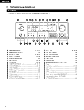
... station select buttons 51, 53) @5 BAND button 52) @6 SIGNAL indicators 34) @7 INPUT mode indicators 34) @8 Remote control sensor (REMOTE SENSOR 16) @9 Power operation indicator (ON/STANDBY) #0 INPUT SELECTOR knob 33) 6 ENGLISH 5 PART NAMES AND FUNCTIONS Front Panel • For details on the functions of these parts, refer to the pages given...
... station select buttons 51, 53) @5 BAND button 52) @6 SIGNAL indicators 34) @7 INPUT mode indicators 34) @8 Remote control sensor (REMOTE SENSOR 16) @9 Power operation indicator (ON/STANDBY) #0 INPUT SELECTOR knob 33) 6 ENGLISH 5 PART NAMES AND FUNCTIONS Front Panel • For details on the functions of these parts, refer to the pages given...
Owners Manual
Page 9
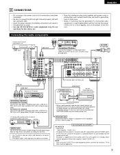
...Infrared retransmitter + + OUTPUT INPUT • When a sold separately) for connections to -room remote control unit (DENON RC-616, 617 or 618) is wired and connected between on and standby from the remote control unit. Subwoofer jack Connect the internal amplifier's subwoofer to the subwoofer terminal. (Refer to ...main room can be generated if a connected audio equipment is used independently without turning the power of the this unit's power is at standby. LINE OUT LINE OUT RL OUTPUT RL CD player RL DIGITAL AUDIO Connecting a CD player Connect the CD player's analog output jacks...
...Infrared retransmitter + + OUTPUT INPUT • When a sold separately) for connections to -room remote control unit (DENON RC-616, 617 or 618) is wired and connected between on and standby from the remote control unit. Subwoofer jack Connect the internal amplifier's subwoofer to the subwoofer terminal. (Refer to ...main room can be generated if a connected audio equipment is used independently without turning the power of the this unit's power is at standby. LINE OUT LINE OUT RL OUTPUT RL CD player RL DIGITAL AUDIO Connecting a CD player Connect the CD player's analog output jacks...
Owners Manual
Page 29
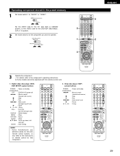
...Set mode switch 2 to the component you want to operate. 1 3 ENGLISH 3 2 3 Operate the component. • For details, refer to the instructions on /standby (ON/SOURCE) 6,7 : Manual search (forward and reverse) 2 : Stop 1 : Play 8,9 : Auto search (cue) 3 : Pause 0~9, +10 : 10... key 29 Digital video disc player (DVD, DVD SETUP) system buttons POWER : Power on/standby (ON/SOURCE) OFF : DENON DVD power off 6,7 : Manual search (forward and reverse) 2 : Stop 1 : Play 8,9 : Auto search (to beginning of track) 3 : Pause 0 ~ 9,...
...Set mode switch 2 to the component you want to operate. 1 3 ENGLISH 3 2 3 Operate the component. • For details, refer to the instructions on /standby (ON/SOURCE) 6,7 : Manual search (forward and reverse) 2 : Stop 1 : Play 8,9 : Auto search (cue) 3 : Pause 0~9, +10 : 10... key 29 Digital video disc player (DVD, DVD SETUP) system buttons POWER : Power on/standby (ON/SOURCE) OFF : DENON DVD power off 6,7 : Manual search (forward and reverse) 2 : Stop 1 : Play 8,9 : Auto search (to beginning of track) 3 : Pause 0 ~ 9,...
Owners Manual
Page 30
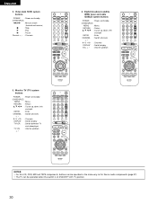
NOTES: • For this CD, CDR, MD and TAPE components, buttons can be operated in the same way as for Denon audio components (page 27). • The TV can be operated when the switch is at DVD/VDP, VCR, TV position. 30 Digital broadcast satellite (...DBS) tuner and cable (CABLE) system buttons POWER : Power on/standby (ON/SOURCE) MENU : Menu RETURN : Return •, ª, 0, 1 : Cursor up, down, left and right ENTER : Enter CHANNEL : Switch channels +, - 0~9, +10 : Channels DISPLAY : Switch ...
NOTES: • For this CD, CDR, MD and TAPE components, buttons can be operated in the same way as for Denon audio components (page 27). • The TV can be operated when the switch is at DVD/VDP, VCR, TV position. 30 Digital broadcast satellite (...DBS) tuner and cable (CABLE) system buttons POWER : Power on/standby (ON/SOURCE) MENU : Menu RETURN : Return •, ª, 0, 1 : Cursor up, down, left and right ENTER : Enter CHANNEL : Switch channels +, - 0~9, +10 : Channels DISPLAY : Switch ...
Owners Manual
Page 32
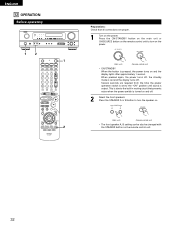
... is set to the "ON" position until sound is output. Press the ON/STANDBY button on the main unit or ON/SOURCE button on the remote control unit to turn the speaker on. (Main unit) (Remote control unit) • ... the display turns off . 2 Select the front speakers. Press the SPEAKER A or B button to turn on the power. (Main unit) (Remote control unit) • ON/STANDBY When the button is pressed, the power turns on and off . Several seconds are proper. 1 Turn on the remote control unit. 32 ENGLISH 12 OPERATION...
... is set to the "ON" position until sound is output. Press the ON/STANDBY button on the main unit or ON/SOURCE button on the remote control unit to turn the speaker on. (Main unit) (Remote control unit) • ... the display turns off . 2 Select the front speakers. Press the SPEAKER A or B button to turn on the power. (Main unit) (Remote control unit) • ON/STANDBY When the button is pressed, the power turns on and off . Several seconds are proper. 1 Turn on the remote control unit. 32 ENGLISH 12 OPERATION...
Owners Manual
Page 61
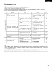
Have you operated the receiver according to the CD, records, tapes, and FM broadcasts, etc. Disconnect the power immediately and contact your store of left and right speakers or left ... with the remote control unit after turning the POWER operation switch on . • Turn off the set is "NORM"). DISPLAY not displayed and the "ON/STANDBY" LED flashes at continuous high power conditions and/or inadequate ventilation. • Switch power off MUTING. • Input digital signals or select input jacks to...
Have you operated the receiver according to the CD, records, tapes, and FM broadcasts, etc. Disconnect the power immediately and contact your store of left and right speakers or left ... with the remote control unit after turning the POWER operation switch on . • Turn off the set is "NORM"). DISPLAY not displayed and the "ON/STANDBY" LED flashes at continuous high power conditions and/or inadequate ventilation. • Switch power off MUTING. • Input digital signals or select input jacks to...

