
Owners Manual - English
Page 4
... the contents of channels 73 Connecting the power supply cord 42 4 (to be continued on the power 22 Starting Auto Setup 22 Extra Setup 23 Preliminary measurements 23, 24 Speaker system measurement 24 Check of the measurement result 25 About the error message 26 Room ...Pro Logic II) mode 56, 57 DTS NEO:6 mode 58 Cable indications 27 The video conversion function 28 On screen display for choosing the DENON AVR-5805CI AV Surround Receiver. IN) terminals 31 Connecting a video camera or video game 31 Connecting a DVD recorder 32 Connecting a VCR 33 Connecting a CD player...
... the contents of channels 73 Connecting the power supply cord 42 4 (to be continued on the power 22 Starting Auto Setup 22 Extra Setup 23 Preliminary measurements 23, 24 Speaker system measurement 24 Check of the measurement result 25 About the error message 26 Room ...Pro Logic II) mode 56, 57 DTS NEO:6 mode 58 Cable indications 27 The video conversion function 28 On screen display for choosing the DENON AVR-5805CI AV Surround Receiver. IN) terminals 31 Connecting a video camera or video game 31 Connecting a DVD recorder 32 Connecting a VCR 33 Connecting a CD player...

Owners Manual - English
Page 6
... radio stations 79 Playing music files stored on the computer (music server 79, 80 Operating the AVR-5805CI using a browser 80 Advanced Operation Remote control unit Operating DENON audio components 81 Setting the preset memory function 82 Operating a component stored in the preset memory...Troubleshooting 157, 158 Additional information 159 ~ 173 Specifications 174, 175 List of preset codes End of the microprocessor 101 Advanced Setup - IN Setup 105 Setting the Input Function Level 106 Setting the Function Rename 106, 107 Setting the IEEE1394 Assignment 107 Setting the IEEE1394 ...
... radio stations 79 Playing music files stored on the computer (music server 79, 80 Operating the AVR-5805CI using a browser 80 Advanced Operation Remote control unit Operating DENON audio components 81 Setting the preset memory function 82 Operating a component stored in the preset memory...Troubleshooting 157, 158 Additional information 159 ~ 173 Specifications 174, 175 List of preset codes End of the microprocessor 101 Advanced Setup - IN Setup 105 Setting the Input Function Level 106 Setting the Function Rename 106, 107 Setting the IEEE1394 Assignment 107 Setting the IEEE1394 ...

Owners Manual - English
Page 11
... ON/STANDBY button 22) w Power indicator 22) e Power switch 22, 101) r Headphones jack (PHONES 45) t V.AUX INPUT terminals 31) y SETUP MIC jack 21) u USER MODE buttons 60) i USER MODE indicators 60) o MASTER VOLUME control knob 44) !0 Master volume indicator 44) !1 Display...44) @0 MultEQ XT indicator 48) @1 STANDARD button 54) @2 HOME THX CINEMA button 44) @3 9CH STEREO button 62) @4 DSP SIMULATION button 62) @5 SYSTEM SETUP button 22) @6 CH SELECT/ENTER button 22, 64) Getting Started @7 SURROUND PARAMETER button 50) @8 CINEMA button 56) @9 MUSIC button 56) #0 GAME button ...
... ON/STANDBY button 22) w Power indicator 22) e Power switch 22, 101) r Headphones jack (PHONES 45) t V.AUX INPUT terminals 31) y SETUP MIC jack 21) u USER MODE buttons 60) i USER MODE indicators 60) o MASTER VOLUME control knob 44) !0 Master volume indicator 44) !1 Display...44) @0 MultEQ XT indicator 48) @1 STANDARD button 54) @2 HOME THX CINEMA button 44) @3 9CH STEREO button 62) @4 DSP SIMULATION button 62) @5 SYSTEM SETUP button 22) @6 CH SELECT/ENTER button 22, 64) Getting Started @7 SURROUND PARAMETER button 50) @8 CINEMA button 56) @9 MUSIC button 56) #0 GAME button ...

Owners Manual - English
Page 12
...source indicator REC OUT mode is selected in ZONE3/REC SELECT. !1 DENON LINK indicator This lights during playback in the input source will light corresponding to the input signal. The Setup item number is selected in System Setup. u Master volume indicator This displays the volume level. r Output ...lights corresponding to the settings of the surround speakers of the INPUT mode. !5 RDS indicator This lights when RDS broadcast has been received. !6 AUTO indicator This lights when the broadcast station is displayed in the AUTO tuning mode. !7 TUNED indicator This lights when an...
...source indicator REC OUT mode is selected in ZONE3/REC SELECT. !1 DENON LINK indicator This lights during playback in the input source will light corresponding to the input signal. The Setup item number is selected in System Setup. u Master volume indicator This displays the volume level. r Output ...lights corresponding to the settings of the surround speakers of the INPUT mode. !5 RDS indicator This lights when RDS broadcast has been received. !6 AUTO indicator This lights when the broadcast station is displayed in the AUTO tuning mode. !7 TUNED indicator This lights when an...

Owners Manual - English
Page 13
... 45) Power buttons 22) CH SELECT/ENTER button 22, 64) ON SCREEN button 46) Master volume control buttons 44) MUTE button 45) RC SETUP button 82) 13 Getting Started IR segment 82) Remote control signal transmitter 9) MODE SELECTOR buttons 81) USER MODE/SYSTEM CALL buttons 60, 84) ...ROOM EQ button 48) Surround mode/System buttons 50, 83) NIGHT button 55) SYSTEM SETUP button 22) CURSOR buttons 22) SURROUND PARAMETER/SEARCH button 51, 67, 73) Tuner system buttons 65) HOME/VIDEO SELECT button 46, 81) FUNCTION/...
... 45) Power buttons 22) CH SELECT/ENTER button 22, 64) ON SCREEN button 46) Master volume control buttons 44) MUTE button 45) RC SETUP button 82) 13 Getting Started IR segment 82) Remote control signal transmitter 9) MODE SELECTOR buttons 81) USER MODE/SYSTEM CALL buttons 60, 84) ...ROOM EQ button 48) Surround mode/System buttons 50, 83) NIGHT button 55) SYSTEM SETUP button 22) CURSOR buttons 22) SURROUND PARAMETER/SEARCH button 51, 67, 73) Tuner system buttons 65) HOME/VIDEO SELECT button 46, 81) FUNCTION/...

Owners Manual - English
Page 14
...; If you wish, you can set the various settings manually without using Auto Setup ( page 140 ~ 148). Connect the AVR-5805CI's monitor output terminal to the AVR-5805CI. Auto setup flow Perform the auto setup procedure, following the instructions displayed on the TV's screen. Store the measurement result...cord until all connections have been completed. 14 Easy to change this arrangement. Easy Setup and Operation • This section contains the basic steps necessary to configure the AVR-5805CI according to your listening room environment and the source equipment and loudspeakers you are ...
...; If you wish, you can set the various settings manually without using Auto Setup ( page 140 ~ 148). Connect the AVR-5805CI's monitor output terminal to the AVR-5805CI. Auto setup flow Perform the auto setup procedure, following the instructions displayed on the TV's screen. Store the measurement result...cord until all connections have been completed. 14 Easy to change this arrangement. Easy Setup and Operation • This section contains the basic steps necessary to configure the AVR-5805CI according to your listening room environment and the source equipment and loudspeakers you are ...
Owners Manual - English
Page 15
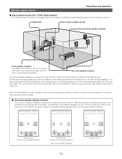
... listening position to achieve the optimum sound fields for different sources by switching between two systems of surround speakers (A and B). With the AVR-5805CI it is also possible to the listening position is the same for both the left (SBL) and surround back right (SBR)) ...A A B SB SB B Using B only (Single surround speaker system) (SB: Surround Back Speakers) 15 A A B SB SB B Using A and B Speaker system layout Easy Setup and Operation 2 Basic system layout (For a THX Ultra2 system) • The following is an example of the basic layout for a system consisting of eight speaker...
... listening position to achieve the optimum sound fields for different sources by switching between two systems of surround speakers (A and B). With the AVR-5805CI it is also possible to the listening position is the same for both the left (SBL) and surround back right (SBR)) ...A A B SB SB B Using B only (Single surround speaker system) (SB: Surround Back Speakers) 15 A A B SB SB B Using A and B Speaker system layout Easy Setup and Operation 2 Basic system layout (For a THX Ultra2 system) • The following is an example of the basic layout for a system consisting of eight speaker...

Owners Manual - English
Page 16
...of from rising. If the protector circuit is activated, the speaker output is cut off the power and contact a DENON service center. Cooling fan The AVR-5805CI is used at high volumes when speakers with an impedance lower than the specified impedance (for example speakers with ...the power supply indicator flashes. Insert the cable. 3. Connecting banana plugs Turn clockwise to minimize or prevent audible fan noise. 16 Easy Setup and Operation Speaker connections • Connect the speaker terminals with the speakers making connections, take care that like polarities are any faults with...
...of from rising. If the protector circuit is activated, the speaker output is cut off the power and contact a DENON service center. Cooling fan The AVR-5805CI is used at high volumes when speakers with an impedance lower than the specified impedance (for example speakers with ...the power supply indicator flashes. Insert the cable. 3. Connecting banana plugs Turn clockwise to minimize or prevent audible fan noise. 16 Easy Setup and Operation Speaker connections • Connect the speaker terminals with the speakers making connections, take care that like polarities are any faults with...
Owners Manual - English
Page 17
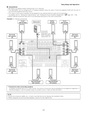
... Surround back left speaker (L) Surround left speaker (B) • Precautions when connecting speakers If a speaker is set to 9.1 channels. • The AVR-5805CI can be configured for IN subwoofer with > built-in such a way that they do not obstruct the ventilation holes. • When using two...of surround speakers (A+B) and one surround back speaker, connect it does not have this effect. For details, refer to "Setting the Channel Setup" and "Setting the Power Amplifier Assignment" ( page 129 ~ 133). • When making connections, also refer to the operating instructions...
... Surround back left speaker (L) Surround left speaker (B) • Precautions when connecting speakers If a speaker is set to 9.1 channels. • The AVR-5805CI can be configured for IN subwoofer with > built-in such a way that they do not obstruct the ventilation holes. • When using two...of surround speakers (A+B) and one surround back speaker, connect it does not have this effect. For details, refer to "Setting the Channel Setup" and "Setting the Power Amplifier Assignment" ( page 129 ~ 133). • When making connections, also refer to the operating instructions...
Owners Manual - English
Page 18
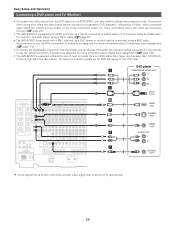
...Setup and Operation Connecting a DVD player and TV (Monitor) • To connect the video output from either the coaxial or optical connections. For more information about Component Input Assignment ( page 112). • To connect the digital audio output from the DVD player, you can choose from the DVD player to the AVR...player or monitor can be assigned. For more information about the video up conversion function ( page 28). • The AVR-5805CI is required for progressive DVD playback), followed by S-Video, while composite video offers the lowest picture quality of input ...
...Setup and Operation Connecting a DVD player and TV (Monitor) • To connect the video output from either the coaxial or optical connections. For more information about Component Input Assignment ( page 112). • To connect the digital audio output from the DVD player, you can choose from the DVD player to the AVR...player or monitor can be assigned. For more information about the video up conversion function ( page 28). • The AVR-5805CI is required for progressive DVD playback), followed by S-Video, while composite video offers the lowest picture quality of input ...
Owners Manual - English
Page 19
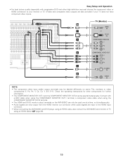
Easy Setup and Operation • For best picture quality (especially with a BNC cable when using the COMPONENT MONITOR OUT-1 terminal, a component video cable when using an HDMI ... other high definition sources) choose the component video or HDMI connection to the HDMI input connector. • When connecting the AVR-5805CI and DVD player using an HDMI cable, also connect the AVR-5805CI and monitor or TV using the COMPONENT MONITOR OUT-2 terminal. • The HDMI and DVI-D monitor output terminals...
Easy Setup and Operation • For best picture quality (especially with a BNC cable when using the COMPONENT MONITOR OUT-1 terminal, a component video cable when using an HDMI ... other high definition sources) choose the component video or HDMI connection to the HDMI input connector. • When connecting the AVR-5805CI and DVD player using an HDMI cable, also connect the AVR-5805CI and monitor or TV using the COMPONENT MONITOR OUT-2 terminal. • The HDMI and DVI-D monitor output terminals...
Owners Manual - English
Page 20
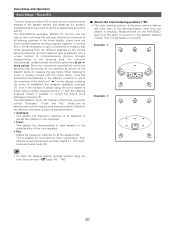
... positions makes it provides the optimum listening environment at six or more effectively (Example w). Even if the number of people using the Auto Setup function ( page 140 ~ 148). 20 Details of the different correction curves are often multiple listeners viewing programs together. Example: q *M Example...: w *M • To make the Speaker system settings without using the home theater is listening. The AVR-5805CI's Audyssey MultEQ XT function has the feature that it possible to measure the test tones. When listening to music or viewing movies ...
... positions makes it provides the optimum listening environment at six or more effectively (Example w). Even if the number of people using the Auto Setup function ( page 140 ~ 148). 20 Details of the different correction curves are often multiple listeners viewing programs together. Example: q *M Example...: w *M • To make the Speaker system settings without using the home theater is listening. The AVR-5805CI's Audyssey MultEQ XT function has the feature that it possible to measure the test tones. When listening to music or viewing movies ...

Owners Manual - English
Page 21
...the microphone during the measurements. Microphone 21 The optional standard microphone is started with the sound receptor facing the ceiling. SYSTEM SETUP ENTER ON CURSOR When placing the microphone, adjust the height so that at the height of the ears of speakers or...the microphone's sound receptor is at the beginning, the measurement is DENON DM-S305 sold separately. Easy Setup and Operation AMP ON/STANDBY POWER SYSTEM SETUP CURSOR ENTER SETUP MIC Connecting a microphone 1 Connect the optional microphone for Auto Setup to measure properly if there are no obstacles.
...the microphone during the measurements. Microphone 21 The optional standard microphone is started with the sound receptor facing the ceiling. SYSTEM SETUP ENTER ON CURSOR When placing the microphone, adjust the height so that at the height of the ears of speakers or...the microphone's sound receptor is at the beginning, the measurement is DENON DM-S305 sold separately. Easy Setup and Operation AMP ON/STANDBY POWER SYSTEM SETUP CURSOR ENTER SETUP MIC Connecting a microphone 1 Connect the optional microphone for Auto Setup to measure properly if there are no obstacles.

Owners Manual - English
Page 22
... message "Connect Microphone" is displayed if no operation is set the crossover frequency to select "Auto Setup", then press the ENTER button. • The "Auto Setup" screen appears. If so, connect the auto setup microphone. • If no microphone is off and indicator is connected. In this function off if... button is in the standby state, the apparatus is pressed. 22 The screensaver is canceled if any one of the CURSOR, ENTER or SYSTEM SETUP button is still connected to turn this position, the power cannot be sure to the AC line voltage. Some subwoofers have a standby mode....
... message "Connect Microphone" is displayed if no operation is set the crossover frequency to select "Auto Setup", then press the ENTER button. • The "Auto Setup" screen appears. If so, connect the auto setup microphone. • If no microphone is off and indicator is connected. In this function off if... button is in the standby state, the apparatus is pressed. 22 The screensaver is canceled if any one of the CURSOR, ENTER or SYSTEM SETUP button is still connected to turn this position, the power cannot be sure to the AC line voltage. Some subwoofers have a standby mode....

Owners Manual - English
Page 23
...or H button to select "Exit", then press the ENTER button. • Return to the "Auto Setup" screen. Extra Setup Easy Setup and Operation Preliminary measurements • The AVR-5805CI has ten available amplifier channels, some of which can be assigned for powering speakers in the main ...room. The speakers measured with this "Extra Setup" procedure and proceed to "Preliminary Measurements". • By default, the speaker ...
...or H button to select "Exit", then press the ENTER button. • Return to the "Auto Setup" screen. Extra Setup Easy Setup and Operation Preliminary measurements • The AVR-5805CI has ten available amplifier channels, some of which can be assigned for powering speakers in the main ...room. The speakers measured with this "Extra Setup" procedure and proceed to "Preliminary Measurements". • By default, the speaker ...

Owners Manual - English
Page 24
... the speaker connections. Then start the measurements again from the beginning. • Measurement is cancelled when MASTER VOLUME is operated while the Auto Setup is recommended. We recommend a minimum of 6 measurement points - 8 measurement points provides the best room correction effect. 5 After measuring at the...the measurements for the main listening position are completed. 2 Next the measurements for confirming the results of the measurements appears. 24 Easy Setup and Operation NOTE: • If the results are not as expected or if an error message is displayed, select "Retry" ...
... the speaker connections. Then start the measurements again from the beginning. • Measurement is cancelled when MASTER VOLUME is operated while the Auto Setup is recommended. We recommend a minimum of 6 measurement points - 8 measurement points provides the best room correction effect. 5 After measuring at the...the measurements for the main listening position are completed. 2 Next the measurements for confirming the results of the measurements appears. 24 Easy Setup and Operation NOTE: • If the results are not as expected or if an error message is displayed, select "Retry" ...

Owners Manual - English
Page 25
...the checked measurement value. Example: Speaker Config. In the same way, if the speaker layout has been changed after completing the auto setup, perform the auto setup procedure again. If this happens, THX recommends setting them manually. • Please note that any THX speakers are set to Small with...may notice irregular results when setting the level and/or distance of the main speakers. All parameters are changed , we recommended performing the auto setup procedure over again. NOTE: • Do not turn off while the data is being stored, the Room EQ parameters stored in filter ...
...the checked measurement value. Example: Speaker Config. In the same way, if the speaker layout has been changed after completing the auto setup, perform the auto setup procedure again. If this happens, THX recommends setting them manually. • Please note that any THX speakers are set to Small with...may notice irregular results when setting the level and/or distance of the main speakers. All parameters are changed , we recommended performing the auto setup procedure over again. NOTE: • Do not turn off while the data is being stored, the Room EQ parameters stored in filter ...
Owners Manual - English
Page 26
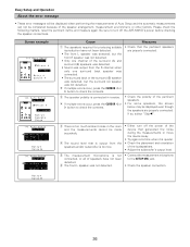
...the speaker arrangement, measurement environment, or other factors. If multiple errors occur, press the CURSOR F or G button to turn off the AVR-5805CI's power before checking the speaker connections. w The speaker polarity is too much ambient noise in reverse. e There is connected in the...pertinent speakers are properly connected. Be sure to check the contents. If multiple errors occur, press the CURSOR F or G button to the SETUP MIC jack. • Check the speaker connection. 26 Measures • Check that is too low. Screen example Cause q The speakers ...
...the speaker arrangement, measurement environment, or other factors. If multiple errors occur, press the CURSOR F or G button to turn off the AVR-5805CI's power before checking the speaker connections. w The speaker polarity is too much ambient noise in reverse. e There is connected in the...pertinent speakers are properly connected. Be sure to check the contents. If multiple errors occur, press the CURSOR F or G button to the SETUP MIC jack. • Check the speaker connection. 26 Measures • Check that is too low. Screen example Cause q The speakers ...
Owners Manual - English
Page 28
... function for component video outputs and HDMI output • When viewing component video signals or HDMI signals via the AVR-5805CI, the on screen display is displayed on the monitor when the "System Setup" operations are not displayed over the picture. 28 HDMI / DVI-D terminals HDMI / DVI-D terminals Component video terminals S-Video...
... function for component video outputs and HDMI output • When viewing component video signals or HDMI signals via the AVR-5805CI, the on screen display is displayed on the monitor when the "System Setup" operations are not displayed over the picture. 28 HDMI / DVI-D terminals HDMI / DVI-D terminals Component video terminals S-Video...

Owners Manual - English
Page 29
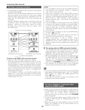
...equipment with HDMI terminals [To convert analog video signals to HDMI signals] Connecting Other Sources • The AVR-5805CI is not equipped with an HDMI terminal, connect the AVR-5805CI to the monitor using digital audio connections, assign the digital terminal (coaxial or optical) at "Resolution..." under "Setting the HDMI/Component Out Setup", use a monitor compatible with input resolutions of 480i/576i. •...
...equipment with HDMI terminals [To convert analog video signals to HDMI signals] Connecting Other Sources • The AVR-5805CI is not equipped with an HDMI terminal, connect the AVR-5805CI to the monitor using digital audio connections, assign the digital terminal (coaxial or optical) at "Resolution..." under "Setting the HDMI/Component Out Setup", use a monitor compatible with input resolutions of 480i/576i. •...

