
Owner's Manual
Page 7
Front Panel 96 Removing the Front Panel 96 Replacing the Front Panel 97 Drive Door 98 Removing the Drive Door 98 Replacing the Drive Door 99 Battery 101 Closing the Computer Cover 102 6 Appendix Specifications 105 Standard Settings 109 Viewing Settings 109 System Setup Screens 109 Boot Sequence 109 Clearing Forgotten Passwords 110 Dell Technical Support Policy...
Front Panel 96 Removing the Front Panel 96 Replacing the Front Panel 97 Drive Door 98 Removing the Drive Door 98 Replacing the Drive Door 99 Battery 101 Closing the Computer Cover 102 6 Appendix Specifications 105 Standard Settings 109 Viewing Settings 109 System Setup Screens 109 Boot Sequence 109 Clearing Forgotten Passwords 110 Dell Technical Support Policy...
Owner's Manual
Page 10
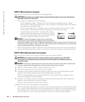
...Japan is 100 V. As you are disconnecting this type of the following safe-handling guidelines. Also, before disconnecting the cable. www.dell.com | support.dell.com SAFETY: When Using Your Computer As you use your computer, observe the following : - Computers with a manual voltage selection... anything inside the computer, unplug the computer to dissipate any cover(s) (including computer covers, bezels, filler brackets, front-panel inserts, and so on) removed. • Your computer is connected to the position that most closely matches the AC power available in on the cable...
...Japan is 100 V. As you are disconnecting this type of the following safe-handling guidelines. Also, before disconnecting the cable. www.dell.com | support.dell.com SAFETY: When Using Your Computer As you use your computer, observe the following : - Computers with a manual voltage selection... anything inside the computer, unplug the computer to dissipate any cover(s) (including computer covers, bezels, filler brackets, front-panel inserts, and so on) removed. • Your computer is connected to the position that most closely matches the AC power available in on the cable...
Owner's Manual
Page 20
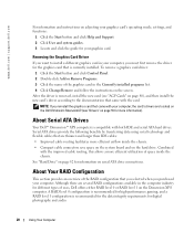
...and Support. 2 Click User and system guides. 3 Locate and click the guide for more information). About Serial ATA Drives Your Dell™ Dimension™ XPS computer is removed, install the new card (see "Drivers" on the screen. A RAID level 0 configuration is recommended for high-performance gaming, and...of the graphics card in the computer industry for information on the hard drive. To remove a graphics card driver: 1 Click the Start button and click Control Panel. 2 Double-click Add or Remove Programs. 3 Click the name of space inside the chassis. • Compact cable ...
...and Support. 2 Click User and system guides. 3 Locate and click the guide for more information). About Serial ATA Drives Your Dell™ Dimension™ XPS computer is removed, install the new card (see "Drivers" on the screen. A RAID level 0 configuration is recommended for high-performance gaming, and...of the graphics card in the computer industry for information on the hard drive. To remove a graphics card driver: 1 Click the Start button and click Control Panel. 2 Double-click Add or Remove Programs. 3 Click the name of space inside the chassis. • Compact cable ...
Owner's Manual
Page 35
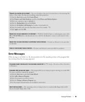
... CALL WAITING (CATCH-PHONE) - A REQUIRED .DLL FILE WAS NOT FOUND - To remove and then reinstall the program: 1 Click the Start button and click Control Panel. 2 Click Add or Remove Programs. 3 Select the program you are trying to remove. 4 Click the Change or Remove Program icon. 5 See the program documentation for instructions on deactivating this feature...
... CALL WAITING (CATCH-PHONE) - A REQUIRED .DLL FILE WAS NOT FOUND - To remove and then reinstall the program: 1 Click the Start button and click Control Panel. 2 Click Add or Remove Programs. 3 Select the program you are trying to remove. 4 Click the Change or Remove Program icon. 5 See the program documentation for instructions on deactivating this feature...
Owner's Manual
Page 39
... THE IEEE 1394 DEVICE IS RECOGNIZED BY WINDOWS® - 1 Click the Start button and click Control Panel. 2 Click Printers and Other Hardware. IF YOU HAVE PROBLEMS WITH AN IEEE 1394 DEVICE NOT PROVIDED BY DELL - REMOVE ANY RECENTLY ADDED HARDWARE TO SEE IF IT RESOLVES THE CONFLICT - See page 59. CHECK THE IEEE...
... THE IEEE 1394 DEVICE IS RECOGNIZED BY WINDOWS® - 1 Click the Start button and click Control Panel. 2 Click Printers and Other Hardware. IF YOU HAVE PROBLEMS WITH AN IEEE 1394 DEVICE NOT PROVIDED BY DELL - REMOVE ANY RECENTLY ADDED HARDWARE TO SEE IF IT RESOLVES THE CONFLICT - See page 59. CHECK THE IEEE...

Owner's Manual
Page 47
...computer. If another monitor is defective. See the monitor documentation for interference. ADJUST THE WINDOWS® DISPLAY SETTINGS - 1 Click the Start button and click Control Panel. 2 Click Appearance and Themes. 3 Click Display and click the Settings tab. 4 Try different settings for Screen resolution and Color quality. Swap the computer and... power cables to determine if the power cable is available, connect it to appear "shaky." If you are using a video extension cable and removing the cable solves the problem, the cable is defective. Solving Problems 47 SWAP THE POWER CABLES -
...computer. If another monitor is defective. See the monitor documentation for interference. ADJUST THE WINDOWS® DISPLAY SETTINGS - 1 Click the Start button and click Control Panel. 2 Click Appearance and Themes. 3 Click Display and click the Settings tab. 4 Try different settings for Screen resolution and Color quality. Swap the computer and... power cables to determine if the power cable is available, connect it to appear "shaky." If you are using a video extension cable and removing the cable solves the problem, the cable is defective. Solving Problems 47 SWAP THE POWER CABLES -
Owner's Manual
Page 59
Conflicts are indicated by reconfiguring the devices or removing the devices from the Device Manager. To see if System Restore is enabled: 1 Click the Start button and click Control Panel. 2 Click Performance and Maintenance. 3 Click System. 4 Click the System Restore tab. 5 Ensure that share the device... if the device has been disabled. 5 Double-click any conflict to resolve a hardware conflict on a computer running Windows XP: 1 Click the Start button and click Control Panel. 2 Click Performance and Maintenance and click System. 3 Click the Hardware tab and click Device Manager. 4 In the ...
Conflicts are indicated by reconfiguring the devices or removing the devices from the Device Manager. To see if System Restore is enabled: 1 Click the Start button and click Control Panel. 2 Click Performance and Maintenance. 3 Click System. 4 Click the System Restore tab. 5 Ensure that share the device... if the device has been disabled. 5 Double-click any conflict to resolve a hardware conflict on a computer running Windows XP: 1 Click the Start button and click Control Panel. 2 Click Performance and Maintenance and click System. 3 Click the Hardware tab and click Device Manager. 4 In the ...
Owner's Manual
Page 63
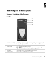
... be on when the computer reads data from or writes data to the hard drive. NOTICE: To avoid losing data, do not use the front-panel connectors. Open the drive door to use the power button to turn off the computer. Open the door to access the floppy and CD/DVD... drives. Removing and Installing Parts Front and Back View of the Computer Front View 1 2 3 4 1 hard-drive activity light 2 power button 3 drive door 4 front-panel door The hard-drive light is on when a device such as your CD player...
... be on when the computer reads data from or writes data to the hard drive. NOTICE: To avoid losing data, do not use the front-panel connectors. Open the drive door to use the power button to turn off the computer. Open the door to access the floppy and CD/DVD... drives. Removing and Installing Parts Front and Back View of the Computer Front View 1 2 3 4 1 hard-drive activity light 2 power button 3 drive door 4 front-panel door The hard-drive light is on when a device such as your CD player...

Owner's Manual
Page 66
www.dell.com | support.dell.com 9 PCI sound card with a network connector card, use the connector on the back panel of a network cable to either a network jack or to attach a record/playback device such as a digital video camera. Use the green line-out connector to.... Use the black surround connector to ensure reliable operation. It is recommended that the network cable has been securely attached. network or broadband jack 66 Removing and Installing Parts If your subwoofer. • IEEE 1394 connector - If you use Category 3 wiring, force the network speed to 10 Mbps to attach ...
www.dell.com | support.dell.com 9 PCI sound card with a network connector card, use the connector on the back panel of a network cable to either a network jack or to attach a record/playback device such as a digital video camera. Use the green line-out connector to.... Use the black surround connector to ensure reliable operation. It is recommended that the network cable has been securely attached. network or broadband jack 66 Removing and Installing Parts If your subwoofer. • IEEE 1394 connector - If you use Category 3 wiring, force the network speed to 10 Mbps to attach ...

Owner's Manual
Page 68
...procedure assumes that the following steps in this section, follow installation and service instructions closely. www.dell.com | support.dell.com Before You Begin This section provides procedures for removing and replacing the components. CAUTION: Before you use of the procedures in the sequence listed:... personal safety. Before you by Dell. NOTICE: To disconnect a network cable, first unplug the cable from the network wall jack. 3 Disconnect any of one , but certain procedures (such as removing the heat-sink blower or the control panel) require the use a wrist grounding...
...procedure assumes that the following steps in this section, follow installation and service instructions closely. www.dell.com | support.dell.com Before You Begin This section provides procedures for removing and replacing the components. CAUTION: Before you use of the procedures in the sequence listed:... personal safety. Before you by Dell. NOTICE: To disconnect a network cable, first unplug the cable from the network wall jack. 3 Disconnect any of one , but certain procedures (such as removing the heat-sink blower or the control panel) require the use a wrist grounding...
Owner's Manual
Page 70
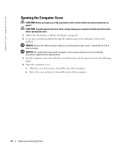
b Raise the cover, and pivot it toward the top of the computer. 70 Removing and Installing Parts CAUTION: To guard against electrical shock, always unplug your computer from the system board. 3 Lay the computer on its side with the ... cover-at least 30 cm (1 ft) of the procedures in "Before You Begin" on page 68. 2 If you begin any of desk top space. www.dell.com | support.dell.com Opening the Computer Cover CAUTION: Before you have installed a padlock through the padlock ring on the back...
b Raise the cover, and pivot it toward the top of the computer. 70 Removing and Installing Parts CAUTION: To guard against electrical shock, always unplug your computer from the system board. 3 Lay the computer on its side with the ... cover-at least 30 cm (1 ft) of the procedures in "Before You Begin" on page 68. 2 If you begin any of desk top space. www.dell.com | support.dell.com Opening the Computer Cover CAUTION: Before you have installed a padlock through the padlock ring on the back...

Owner's Manual
Page 73
Removing and Installing Parts 73 System Board Components password jumper (PASS) hard-drive connector (PRI_IDE) secondary drive connector (SEC_IDE) floppy-drive connector (FDD) battery socket (... (2, 4) power connector (PWR) memory module connectors (1, 3) processor and heatsink connector (CPU_PIN_#_A1) rear fan connector (REAR_FAN2) rear fan connector (REAR_FAN1) SCSI_LED header (SCSI_LED) front-panel connector (FRONT_PANEL) standby power light (PWR_LED) serial ATA connector (SATA_1) internal speaker (SPKR) clear CMOS jumper (CMOS) front fan (FRONT_FAN) serial ATA connector (SATA_0) AGP...
Removing and Installing Parts 73 System Board Components password jumper (PASS) hard-drive connector (PRI_IDE) secondary drive connector (SEC_IDE) floppy-drive connector (FDD) battery socket (... (2, 4) power connector (PWR) memory module connectors (1, 3) processor and heatsink connector (CPU_PIN_#_A1) rear fan connector (REAR_FAN2) rear fan connector (REAR_FAN1) SCSI_LED header (SCSI_LED) front-panel connector (FRONT_PANEL) standby power light (PWR_LED) serial ATA connector (SATA_1) internal speaker (SPKR) clear CMOS jumper (CMOS) front fan (FRONT_FAN) serial ATA connector (SATA_0) AGP...
Owner's Manual
Page 87
... that came with the drive for instructions on installing any software required for the fan and cooling vents. 8 Close the computer cover (see page 102). Removing and Installing Parts 87 NOTICE: To connect a network cable, first plug the cable into the network wall jack and then plug it pops out. 7 Check... until it into the computer. 9 Connect your computer and devices to the floppy drive. 6 If you are installing a new floppy drive rather than replacing a drive, remove the front-panel inserts.
... that came with the drive for instructions on installing any software required for the fan and cooling vents. 8 Close the computer cover (see page 102). Removing and Installing Parts 87 NOTICE: To connect a network cable, first plug the cable into the network wall jack and then plug it pops out. 7 Check... until it into the computer. 9 Connect your computer and devices to the floppy drive. 6 If you are installing a new floppy drive rather than replacing a drive, remove the front-panel inserts.

Owner's Manual
Page 96
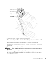
...Installing the Processor" on page 81). 4 Release the front panel by pressing each of the procedures in this section, follow the safety instructions on . Front Panel CAUTION: Before you are seven release tabs. 96 Removing and Installing Parts There are replacing the processor, leave the ...the computer cover (see page 102). If you begin any of the front-panel release tabs. www.dell.com | support.dell.com release lever processor socket 6 Remove the processor from the socket. Removing the Front Panel 1 Follow the instructions in the release position so that the socket is ready ...
...Installing the Processor" on page 81). 4 Release the front panel by pressing each of the procedures in this section, follow the safety instructions on . Front Panel CAUTION: Before you are seven release tabs. 96 Removing and Installing Parts There are replacing the processor, leave the ...the computer cover (see page 102). If you begin any of the front-panel release tabs. www.dell.com | support.dell.com release lever processor socket 6 Remove the processor from the socket. Removing the Front Panel 1 Follow the instructions in the release position so that the socket is ready ...
Owner's Manual
Page 97
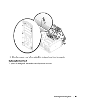
Removing and Installing Parts 97 Replacing the Front Panel To replace the front panel, perform the removal procedure in reverse. 5 Close the computer cover halfway and pull the front panel away from the computer.
Removing and Installing Parts 97 Replacing the Front Panel To replace the front panel, perform the removal procedure in reverse. 5 Close the computer cover halfway and pull the front panel away from the computer.
Owner's Manual
Page 139
..., 13 Owner's Manual, 14 setup diagram, 14 doors drive door, removing, 98 drive door, replacing, 99 front panel, 64 opening , 70 D Dell contacting, 112 Dell (continued) support policy, 111 support website, 13, 38 Dell Diagnostics, 52 Dell Dimension Help file accessing, 30 diagnostic lights, 49 diagnostics Dell, 52 lights, 49 display. Index A AGP cards, 80 installing, 81...
..., 13 Owner's Manual, 14 setup diagram, 14 doors drive door, removing, 98 drive door, replacing, 99 front panel, 64 opening , 70 D Dell contacting, 112 Dell (continued) support policy, 111 support website, 13, 38 Dell Diagnostics, 52 Dell Dimension Help file accessing, 30 diagnostic lights, 49 diagnostics Dell, 52 lights, 49 display. Index A AGP cards, 80 installing, 81...
Owner's Manual
Page 140
... supply, 66 processor, 66 Files and Settings Transfer Wizard, 22 floppy drive installing, 86 problems, 31 removing, 85 front panel removing, 96 replacing, 97 H hard drive activity light, 64 installing, 83 problems, 33 removing, 82 hardware conflicts, 59 Dell Diagnostics, 52 problems, 38 Hardware Troubleshooter, 59 headphone connector, 65 Help and Support Center, 14 help...
... supply, 66 processor, 66 Files and Settings Transfer Wizard, 22 floppy drive installing, 86 problems, 31 removing, 85 front panel removing, 96 replacing, 97 H hard drive activity light, 64 installing, 83 problems, 33 removing, 82 hardware conflicts, 59 Dell Diagnostics, 52 problems, 38 Hardware Troubleshooter, 59 headphone connector, 65 Help and Support Center, 14 help...


