
Specifications
Page 2
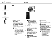
Specifications Front Front Back Views 1 2 3 5 4 Top 1 Media-card reader light Turns on when the media‑card reader is in use. 2 Media-card reader Reads from and writes to media cards. 3 Optical-drive bays (2) Allows to open or close the optical drive tray. Provides data transfer speeds up to 5 Gbps. 5 Optical-drive eject buttons (2) Press to install optical drives if not already installed. 4 USB 3.0 ports (2) Connect peripherals such as storage devices, printers, and so on.
Specifications Front Front Back Views 1 2 3 5 4 Top 1 Media-card reader light Turns on when the media‑card reader is in use. 2 Media-card reader Reads from and writes to media cards. 3 Optical-drive bays (2) Allows to open or close the optical drive tray. Provides data transfer speeds up to 5 Gbps. 5 Optical-drive eject buttons (2) Press to install optical drives if not already installed. 4 USB 3.0 ports (2) Connect peripherals such as storage devices, printers, and so on.

Specifications
Page 3
... audio output. 5 HDMI port Connect a TV or another HDMI‑in enabled device. Specifications Back Front Back Views 1 2 3 4 5 6 10 7 9 8 Top 1 Power port Connect a power cable to provide power to your computer. The two lights next to the connector indicate the connectivity status and network activity. 3 USB 2.0 ports (2) Connect peripherals such as storage devices, printers, and so on . Provides data transfer speeds up to 5 Gbps. 7 Audio ports (6) Connect speakers. 8 Expansion-card slots (4) Provide access to the interior of your computer. 2 Network port Connect an Ethernet...
... audio output. 5 HDMI port Connect a TV or another HDMI‑in enabled device. Specifications Back Front Back Views 1 2 3 4 5 6 10 7 9 8 Top 1 Power port Connect a power cable to provide power to your computer. The two lights next to the connector indicate the connectivity status and network activity. 3 USB 2.0 ports (2) Connect peripherals such as storage devices, printers, and so on . Provides data transfer speeds up to 5 Gbps. 7 Audio ports (6) Connect speakers. 8 Expansion-card slots (4) Provide access to the interior of your computer. 2 Network port Connect an Ethernet...
Specifications
Page 4
... hold for recording sound, making audio calls, making video calls, and so on. 4 Headphone port Connect a pair of headphones or speakers. 5 Accessory tray Place accesories such as headphones, USB devices, and so on. 6 Power button Press to turn on the computer to charge your USB devices even when your devices using the PowerShare port. NOTE: Certain USB devices may not charge when the computer is turned off or in BIOS setup program. For...
... hold for recording sound, making audio calls, making video calls, and so on. 4 Headphone port Connect a pair of headphones or speakers. 5 Accessory tray Place accesories such as headphones, USB devices, and so on. 6 Power button Press to turn on the computer to charge your USB devices even when your devices using the PowerShare port. NOTE: Certain USB devices may not charge when the computer is turned off or in BIOS setup program. For...
Specifications
Page 6
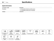
Views System information Computer model Processor Chipset Specifications XPS 8900 • 6th Generation Intel Core i5 Processor • 6th Generation Intel Core i7 Processor Intel Z170 Dimensions and weight System information Memory Ports and connectors Communications Video Media-card reader Power ratings Computer environment Audio Storage
Views System information Computer model Processor Chipset Specifications XPS 8900 • 6th Generation Intel Core i5 Processor • 6th Generation Intel Core i7 Processor Intel Z170 Dimensions and weight System information Memory Ports and connectors Communications Video Media-card reader Power ratings Computer environment Audio Storage

Specifications
Page 7
Views Memory Slot Type Speed Configurations supported Specifications Four DIMM slots DDR4 2133 MHz 8 GB, 16 GB, 24 GB, and 32 GB Dimensions and weight System information Memory Ports and connectors Communications Video Media-card reader Power ratings Computer environment Audio Storage
Views Memory Slot Type Speed Configurations supported Specifications Four DIMM slots DDR4 2133 MHz 8 GB, 16 GB, 24 GB, and 32 GB Dimensions and weight System information Memory Ports and connectors Communications Video Media-card reader Power ratings Computer environment Audio Storage

Specifications
Page 12
Views Storage Interface Hard drives Solid-state drive (SSD) Optical drive (optional) Specifications • SATA 3 Gbps for optical drive • SATA 6 Gbps for hard drive • M.2 for SSD Three 3.5-inch hard drives One M.2 slot Two 5.25-inch DVD+/-RW and Blu-ray disc writer Dimensions and weight System information Memory Ports and connectors Communications Video Media-card reader Power ratings Computer environment Audio Storage
Views Storage Interface Hard drives Solid-state drive (SSD) Optical drive (optional) Specifications • SATA 3 Gbps for optical drive • SATA 6 Gbps for hard drive • M.2 for SSD Three 3.5-inch hard drives One M.2 slot Two 5.25-inch DVD+/-RW and Blu-ray disc writer Dimensions and weight System information Memory Ports and connectors Communications Video Media-card reader Power ratings Computer environment Audio Storage

Specifications
Page 15
...Memory Ports and connectors Communications Video Media-card reader Power ratings Computer environment Audio Storage Views Specifications Computer environment Airborne contaminant level Relative humidity (maximum) Temperature range Vibration (maximum)* Shock (maximum) Altitude (maximum) G2 or lower as defined by ISA-S71.04-1985 20% to 80% (noncondensing) Operating... using a random vibration spectrum that simulates user environment. † Measured using a 2 ms half-sine pulse when the hard drive is in use. ‡ Measured using a 2 ms half-sine pulse when the hard-drive head...
...Memory Ports and connectors Communications Video Media-card reader Power ratings Computer environment Audio Storage Views Specifications Computer environment Airborne contaminant level Relative humidity (maximum) Temperature range Vibration (maximum)* Shock (maximum) Altitude (maximum) G2 or lower as defined by ISA-S71.04-1985 20% to 80% (noncondensing) Operating... using a random vibration spectrum that simulates user environment. † Measured using a 2 ms half-sine pulse when the hard drive is in use. ‡ Measured using a 2 ms half-sine pulse when the hard-drive head...
Service Manual
Page 3
Contents Before working inside your computer 11 Before you begin 11 Safety instructions 11 Recommended tools 12 After working inside your computer 14 Technical overview 15 Inside view of your computer 15 System-board components 16 Removing the computer cover 18 Procedure...18 Replacing the computer cover 19 Procedure...19 Post-requisites 19 Removing the memory modules 20 Prerequisites...20 Procedure...20 Replacing the memory modules 22 Procedure...22 Post-requisites 23 Removing the chassis fan 24 Prerequisites...24 Procedure...24 3
Contents Before working inside your computer 11 Before you begin 11 Safety instructions 11 Recommended tools 12 After working inside your computer 14 Technical overview 15 Inside view of your computer 15 System-board components 16 Removing the computer cover 18 Procedure...18 Replacing the computer cover 19 Procedure...19 Post-requisites 19 Removing the memory modules 20 Prerequisites...20 Procedure...20 Replacing the memory modules 22 Procedure...22 Post-requisites 23 Removing the chassis fan 24 Prerequisites...24 Procedure...24 3
Service Manual
Page 9
... power-supply unit 94 Prerequisites...94 Procedure...94 Replacing the power-supply unit 96 Procedure...96 Post-requisites 96 Removing the system board 97 Prerequisites...97 Procedure...97 Replacing the system board 99 Procedure...99 Post-requisites 99 Entering the Service Tag in the BIOS setup program 100 BIOS setup program 101 Overview...101 Entering BIOS setup program 101 Clearing forgotten passwords 101 Prerequisites 102 Procedure 102 Post-requisites 102 Clearing CMOS settings...
... power-supply unit 94 Prerequisites...94 Procedure...94 Replacing the power-supply unit 96 Procedure...96 Post-requisites 96 Removing the system board 97 Prerequisites...97 Procedure...97 Replacing the system board 99 Procedure...99 Post-requisites 99 Entering the Service Tag in the BIOS setup program 100 BIOS setup program 101 Overview...101 Entering BIOS setup program 101 Clearing forgotten passwords 101 Prerequisites 102 Procedure 102 Post-requisites 102 Clearing CMOS settings...
Service Manual
Page 11
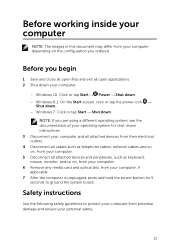
... computer. 6 Remove any media card and optical disc from your computer. - Windows 10: Click or tap Start → Power → Shut down instructions. 3 Disconnect your computer and all attached devices from their electrical outlets. 4 Disconnect all cables such as telephone cables, network cables and so on, from your computer. 5 Disconnect all attached devices and peripherals, such as keyboard, mouse, monitor, and so on the configuration you ordered. Before working inside your...
... computer. 6 Remove any media card and optical disc from your computer. - Windows 10: Click or tap Start → Power → Shut down instructions. 3 Disconnect your computer and all attached devices from their electrical outlets. 4 Disconnect all cables such as telephone cables, network cables and so on, from your computer. 5 Disconnect all attached devices and peripherals, such as keyboard, mouse, monitor, and so on the configuration you ordered. Before working inside your...
Service Manual
Page 12
... any installed card from the media-card reader. CAUTION: You should only perform troubleshooting and repairs as the metal at the back of the computer. While you must disengage before opening the computer cover or panels. When connecting cables, ensure that you work surface is not covered by touching an unpainted metal surface, such as authorized or directed by their edges and avoid touching pins...
... any installed card from the media-card reader. CAUTION: You should only perform troubleshooting and repairs as the metal at the back of the computer. While you must disengage before opening the computer cover or panels. When connecting cables, ensure that you work surface is not covered by touching an unpainted metal surface, such as authorized or directed by their edges and avoid touching pins...
Service Manual
Page 14
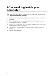
After working inside your computer CAUTION: Leaving stray or loose screws inside your computer may severely damage your computer. 1 Replace all screws and ensure that no stray screws remain inside your computer. 2 Connect any external devices, peripherals, and cables you removed before working on your computer. 3 Replace any media cards, discs, and any other parts that you removed before working on your computer. 4 Connect your computer and all attached devices to their electrical outlets. 5 Turn on your computer. 14
After working inside your computer CAUTION: Leaving stray or loose screws inside your computer may severely damage your computer. 1 Replace all screws and ensure that no stray screws remain inside your computer. 2 Connect any external devices, peripherals, and cables you removed before working on your computer. 3 Replace any media cards, discs, and any other parts that you removed before working on your computer. 4 Connect your computer and all attached devices to their electrical outlets. 5 Turn on your computer. 14

Service Manual
Page 47
... at www.dell.com/regulatory_compliance. Removing the primary harddrive WARNING: Before working inside your computer, read the safety information that secure the primary hard-drive to the chassis. 47 CAUTION: Hard drives are fragile. Procedure 1 Disconnect the power and data cables from the primary hard-drive. 2 Remove the screws that shipped with your computer and follow the instructions in After working inside your computer. After working inside your computer...
... at www.dell.com/regulatory_compliance. Removing the primary harddrive WARNING: Before working inside your computer, read the safety information that secure the primary hard-drive to the chassis. 47 CAUTION: Hard drives are fragile. Procedure 1 Disconnect the power and data cables from the primary hard-drive. 2 Remove the screws that shipped with your computer and follow the instructions in After working inside your computer. After working inside your computer...

Service Manual
Page 49
....dell.com/regulatory_compliance. Post-requisites Replace the computer cover. 49 After working inside your computer, follow the steps in After working inside your computer. Replacing the primary harddrive WARNING: Before working inside your computer, read the safety information that secure the primary hard-drive to the chassis. 3 Connect the power and data cables to the primary hard-drive. CAUTION: Hard drives are fragile. Procedure 1 Slide the primary hard-drive into the chassis. 2 Replace...
....dell.com/regulatory_compliance. Post-requisites Replace the computer cover. 49 After working inside your computer, follow the steps in After working inside your computer. Replacing the primary harddrive WARNING: Before working inside your computer, read the safety information that secure the primary hard-drive to the chassis. 3 Connect the power and data cables to the primary hard-drive. CAUTION: Hard drives are fragile. Procedure 1 Slide the primary hard-drive into the chassis. 2 Replace...

Service Manual
Page 60
... the front of the computer. 2 Replace the screws that shipped with your computer and follow the instructions in Before working inside your computer. Post-requisites 1 Replace the front bezel. 2 Replace the computer cover. 60 Replacing the tertiary harddrive WARNING: Before working inside your computer, read the safety information that secure the tertiary hard-drive to the chassis. 3 Connect the power and data cables to the tertiary hard-drive.
... the front of the computer. 2 Replace the screws that shipped with your computer and follow the instructions in Before working inside your computer. Post-requisites 1 Replace the front bezel. 2 Replace the computer cover. 60 Replacing the tertiary harddrive WARNING: Before working inside your computer, read the safety information that secure the tertiary hard-drive to the chassis. 3 Connect the power and data cables to the tertiary hard-drive.
Service Manual
Page 94
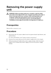
... that shipped with your computer and follow the instructions in Before working inside your computer. Removing the power-supply unit WARNING: Before working inside your computer, read the safety information that secure the power-supply unit to release the power-supply unit from the system board, hard drives, and optical drives. Prerequisites Remove the computer cover. Procedure 1 Disconnect the DC power cables from the power-supply clamps. 94 For more information, see the...
... that shipped with your computer and follow the instructions in Before working inside your computer. Removing the power-supply unit WARNING: Before working inside your computer, read the safety information that secure the power-supply unit to release the power-supply unit from the system board, hard drives, and optical drives. Prerequisites Remove the computer cover. Procedure 1 Disconnect the DC power cables from the power-supply clamps. 94 For more information, see the...
Service Manual
Page 96
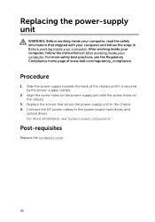
... with the screw holes on the power-supply unit with your computer and follow the instructions in Before working inside your computer. Post-requisites Replace the computer cover. 96 Replacing the power-supply unit WARNING: Before working inside your computer, read the safety information that secure the power-supply unit to the chassis. 4 Connect the DC power cables to the system board, hard drives, and optical drives. For more safety best practices...
... with the screw holes on the power-supply unit with your computer and follow the instructions in Before working inside your computer. Post-requisites Replace the computer cover. 96 Replacing the power-supply unit WARNING: Before working inside your computer, read the safety information that secure the power-supply unit to the chassis. 4 Connect the DC power cables to the system board, hard drives, and optical drives. For more safety best practices...
Service Manual
Page 97
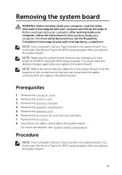
... replace the system board. Removing the system board WARNING: Before working inside your computer, read the safety information that you can reconnect the cables correctly after you replace the system board. 97 Prerequisites 1 Remove the computer cover. 2 Remove the wireless card. 3 Remove the memory modules. 4 Remove the graphics-card bracket. 5 Remove the graphics card. 6 Remove the processor fan and heat sink assembly. 7 Remove the processor. 8 Disconnect all cables connected to the BIOS using the BIOS setup program. You must enter the Service Tag in the BIOS setup...
... replace the system board. Removing the system board WARNING: Before working inside your computer, read the safety information that you can reconnect the cables correctly after you replace the system board. 97 Prerequisites 1 Remove the computer cover. 2 Remove the wireless card. 3 Remove the memory modules. 4 Remove the graphics-card bracket. 5 Remove the graphics card. 6 Remove the processor fan and heat sink assembly. 7 Remove the processor. 8 Disconnect all cables connected to the BIOS using the BIOS setup program. You must enter the Service Tag in the BIOS setup...

Service Manual
Page 99
Procedure 1 Slide the ports on the system board into the slots on the chassis and align the screw holes on the system board with your computer and follow the instructions in After working inside your computer. Post-requisites 1 Replacing the processor. 2 Replacing the processor fan and heat sink assembly. 3 Remove the graphics card. 4 Replacing the memory modules. 5 Replacing the wireless card. 6 Replacing the computer cover. 99 For more information, see the Regulatory Compliance...
Procedure 1 Slide the ports on the system board into the slots on the chassis and align the screw holes on the system board with your computer and follow the instructions in After working inside your computer. Post-requisites 1 Replacing the processor. 2 Replacing the processor fan and heat sink assembly. 3 Remove the graphics card. 4 Replacing the memory modules. 5 Replacing the wireless card. 6 Replacing the computer cover. 99 For more information, see the Regulatory Compliance...
Service Manual
Page 101
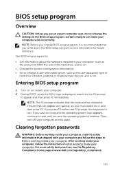
... system configuration information. • Set or change a user-selectable option, such as the user password, type of hard drive installed, enabling or disabling base devices, and so on. NOTE: The F2 prompt indicates that you must watch for future reference. Certain changes can appear very quickly, so you write down the BIOS setup program screen information for the F2 prompt to : • Get information about the hardware installed in Before working inside...
... system configuration information. • Set or change a user-selectable option, such as the user password, type of hard drive installed, enabling or disabling base devices, and so on. NOTE: The F2 prompt indicates that you must watch for future reference. Certain changes can appear very quickly, so you write down the BIOS setup program screen information for the F2 prompt to : • Get information about the hardware installed in Before working inside...


