Owner's Manual
Page 1
... Back I/O Connectors 17 Attaching the Computer Stand 18 Connecting Monitors 20 Connecting a Monitor (Without an Adapter 20 Connecting a Monitor (With an Adapter 21 Connecting a Monitor in a Dual Graphics Card Configuration 22 Connecting Two or More Monitors 23 Connecting a TV 24 Changing the Display Settings to Support Two or More Monitors . . . . . 25 About Your RAID Configuration 25 RAID Level 0 Configuration 26 RAID Level 1 Configuration 26 Configuring Your Hard Drives for RAID 27 Using the Nvidia MediaShield ROM Utility 28 Using Nvidia MediaShield 29 Playing CDs and DVDs 32...
... Back I/O Connectors 17 Attaching the Computer Stand 18 Connecting Monitors 20 Connecting a Monitor (Without an Adapter 20 Connecting a Monitor (With an Adapter 21 Connecting a Monitor in a Dual Graphics Card Configuration 22 Connecting Two or More Monitors 23 Connecting a TV 24 Changing the Display Settings to Support Two or More Monitors . . . . . 25 About Your RAID Configuration 25 RAID Level 0 Configuration 26 RAID Level 1 Configuration 26 Configuring Your Hard Drives for RAID 27 Using the Nvidia MediaShield ROM Utility 28 Using Nvidia MediaShield 29 Playing CDs and DVDs 32...
Owner's Manual
Page 9
... configuration, product specifications, and white papers • Downloads - Certified drivers, patches, and software updates • Desktop System Software (DSS)- processors, optical drives, and USB devices. If you should also reinstall the DSS utility. DSS automatically detects your computer and operating system and installs the updates appropriate for correct operation of your Service Tag or product model. 2 Select Drivers & Downloads, and then click Go. Find It Here • Solutions - DSS is NOTE: The support.dell...
... configuration, product specifications, and white papers • Downloads - Certified drivers, patches, and software updates • Desktop System Software (DSS)- processors, optical drives, and USB devices. If you should also reinstall the DSS utility. DSS automatically detects your computer and operating system and installs the updates appropriate for correct operation of your Service Tag or product model. 2 Select Drivers & Downloads, and then click Go. Find It Here • Solutions - DSS is NOTE: The support.dell...

Owner's Manual
Page 15
... additional network connector card, use Category 3 wiring, force the network speed to 10 Mbps to be in a steady "on your network or broadband device, and then connect the other end of network traffic may make this light appear to ensure reliable operation. Turn off the computer and any attached devices before you have a USB mouse, plug it into a USB connector. Setting Up and Using Your Computer 17 A good connection exists between a 100-Mbps network and...
... additional network connector card, use Category 3 wiring, force the network speed to 10 Mbps to be in a steady "on your network or broadband device, and then connect the other end of network traffic may make this light appear to ensure reliable operation. Turn off the computer and any attached devices before you have a USB mouse, plug it into a USB connector. Setting Up and Using Your Computer 17 A good connection exists between a 100-Mbps network and...
Owner's Manual
Page 21
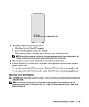
... computer window, click Turn off and not in a dual graphics card configuration, multi-GPU technology must be disabled. To disable multi-GPU, see "Changing the Display Settings to Support Two or More Monitors" on page 25. NOTE: In order to connect and use the (white) DVI port on the primary graphics card. primary video card 1 Turn off the computer and all attached devices from their electrical outlets. 3 Connect the DVI or VGA connector of your monitor...
... computer window, click Turn off and not in a dual graphics card configuration, multi-GPU technology must be disabled. To disable multi-GPU, see "Changing the Display Settings to Support Two or More Monitors" on page 25. NOTE: In order to connect and use the (white) DVI port on the primary graphics card. primary video card 1 Turn off the computer and all attached devices from their electrical outlets. 3 Connect the DVI or VGA connector of your monitor...
Owner's Manual
Page 22
... procedures in this section, follow the safety instructions in a power management mode. To connect two or more monitors to the DVI port(s) on page 21. 4 Change the display settings to your computer. 1 Turn off the computer and all attached devices: a Click Start, then click Turn Off Computer. To connect the VGA connectors of the operating system, and then turns off . An S-video cable is not included with your TV to the...
... procedures in this section, follow the safety instructions in a power management mode. To connect two or more monitors to the DVI port(s) on page 21. 4 Change the display settings to your computer. 1 Turn off the computer and all attached devices: a Click Start, then click Turn Off Computer. To connect the VGA connectors of the operating system, and then turns off . An S-video cable is not included with your TV to the...

Owner's Manual
Page 23
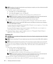
... MediaShield ROM Utility" on page 28 for users that desire a high level of data integrity. Changing the Display Settings to Support Two or More Monitors NOTE: Dual graphics card configurations with a DVI or VGA connector as needed, with multi-GPU technology enabled support only a single monitor. Your Dell XPS computer supports RAID level 0 and RAID level 1. For more monitors in the computer industry for your graphics card). 4 Connect the other end of the S-video cable to the S-video input connector on...
... MediaShield ROM Utility" on page 28 for users that desire a high level of data integrity. Changing the Display Settings to Support Two or More Monitors NOTE: Dual graphics card configurations with a DVI or VGA connector as needed, with multi-GPU technology enabled support only a single monitor. Your Dell XPS computer supports RAID level 0 and RAID level 1. For more monitors in the computer industry for your graphics card). 4 Connect the other end of the S-video cable to the S-video input connector on...

Owner's Manual
Page 56
... for monitor cable connectors to have missing pins.) CHECK THE MONITOR POWER LIGHT - • If the power light is lit or blinking, the monitor has power. • If the power light is off, firmly press the button to ensure that the monitor cable is blinking, press a key on the setup diagram for instructions on page 61. CHECK THE MONITOR CABLE CONNECTION - • Ensure that the monitor cable is connected to the correct graphics card (for dual graphics card configurations). • If you are using the optional...
... for monitor cable connectors to have missing pins.) CHECK THE MONITOR POWER LIGHT - • If the power light is lit or blinking, the monitor has power. • If the power light is off, firmly press the button to ensure that the monitor cable is blinking, press a key on the setup diagram for instructions on page 61. CHECK THE MONITOR CABLE CONNECTION - • Ensure that the monitor cable is connected to the correct graphics card (for dual graphics card configurations). • If you are using the optional...
Owner's Manual
Page 60
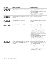
... reinstalled all modules without error. • If available, install working memory of the same type into your computer (see "Memory" on page 127). • If the problem persists, contact Dell (see "Contacting Dell" on page 145). 62 Advanced Troubleshooting A possible floppy drive or hard drive failure has Reseat all cable connections. If the computer starts normally, continue to install additional memory modules (one module (see "Installing Memory" on page 82) and...
... reinstalled all modules without error. • If available, install working memory of the same type into your computer (see "Memory" on page 127). • If the problem persists, contact Dell (see "Contacting Dell" on page 145). 62 Advanced Troubleshooting A possible floppy drive or hard drive failure has Reseat all cable connections. If the computer starts normally, continue to install additional memory modules (one module (see "Installing Memory" on page 82) and...

Owner's Manual
Page 68
.... NOTE: Calendar dates with less than 200 MB of free hard-disk space available, System Restore is enabled: 1 Click Start, then click Control Panel. 2 Under Pick a Category, click Performance and Maintenance. 3 Click System. 70 Advanced Troubleshooting Enabling or Disabling System Restore If you reinstall Windows XP with available restore points appear in bold. The System Restore process collects necessary data, then restarts the computer. 4 Under Undo Complete...
.... NOTE: Calendar dates with less than 200 MB of free hard-disk space available, System Restore is enabled: 1 Click Start, then click Control Panel. 2 Under Pick a Category, click Performance and Maintenance. 3 Click System. 70 Advanced Troubleshooting Enabling or Disabling System Restore If you reinstall Windows XP with available restore points appear in bold. The System Restore process collects necessary data, then restarts the computer. 4 Under Undo Complete...

Owner's Manual
Page 78
...and Installing Parts otherwise these must be left empty 3 hard drive fan connector (FAN_HDD) 17 PCI card slot (SLOT6) 4 IDE drive connector (IDE) 18 PCI-Express x8 card slot (SLOT7) 5 front I/O panel connector (FRONTPANEL) 19 RTC reset jumper (RTCRST) 6 back LED connector 20 battery socket (BATTERY) 7 FlexBay connector (INT_USB) 21 password jumper (PASSWORD) 8 main power connector (POWER1) 22 power connector (POWER2) 9 SATA connectors (SATA0-5) 23 floppy drive (DSKT) 10 front USB connector (FRNT_USB) 24 card cage fan connector (FAN_CAGE) 11 front panel 1394 connector (FP1394...
...and Installing Parts otherwise these must be left empty 3 hard drive fan connector (FAN_HDD) 17 PCI card slot (SLOT6) 4 IDE drive connector (IDE) 18 PCI-Express x8 card slot (SLOT7) 5 front I/O panel connector (FRONTPANEL) 19 RTC reset jumper (RTCRST) 6 back LED connector 20 battery socket (BATTERY) 7 FlexBay connector (INT_USB) 21 password jumper (PASSWORD) 8 main power connector (POWER1) 22 power connector (POWER2) 9 SATA connectors (SATA0-5) 23 floppy drive (DSKT) 10 front USB connector (FRNT_USB) 24 card cage fan connector (FAN_CAGE) 11 front panel 1394 connector (FP1394...

Owner's Manual
Page 95
... network cable to the add-in network connector: 1 Enter system setup (see "Entering System Setup" on page 132), select Integrated NIC Controller, and then change the setting to On. 2 Connect the network cable to the integrated connector on the back panel. Drives Your computer supports: • Six SATA devices (hard drives or optical drives) • Two IDE devices (two hard drives or two optical drives) • One floppy drive • One Media Card Reader NOTICE: When removing and replacing drives, be sure to leave the drive data and power cables connected...
... network cable to the add-in network connector: 1 Enter system setup (see "Entering System Setup" on page 132), select Integrated NIC Controller, and then change the setting to On. 2 Connect the network cable to the integrated connector on the back panel. Drives Your computer supports: • Six SATA devices (hard drives or optical drives) • Two IDE devices (two hard drives or two optical drives) • One floppy drive • One Media Card Reader NOTICE: When removing and replacing drives, be sure to leave the drive data and power cables connected...

Owner's Manual
Page 112
... turn them on page 104). 4 Disconnect the power and data cables from the system board and set it in to the network port or device and then plug it aside. 114 Removing and Installing Parts NOTE: If you begin any software required for drive operation. 12 Enter system setup (see "Entering System Setup" on page 125). Removing a CD/DVD Drive 1 Follow the procedures in "Before You Begin" on page 75. 2 Remove the computer cover...
... turn them on page 104). 4 Disconnect the power and data cables from the system board and set it in to the network port or device and then plug it aside. 114 Removing and Installing Parts NOTE: If you begin any software required for drive operation. 12 Enter system setup (see "Entering System Setup" on page 125). Removing a CD/DVD Drive 1 Follow the procedures in "Before You Begin" on page 75. 2 Remove the computer cover...

Owner's Manual
Page 116
...: To connect a network cable, first plug the cable in to the network port or device and then plug it in to the computer. 12 Connect your computer and devices to their electrical outlets, and turn them on page 132) and select the appropriate Drive option. 118 Removing and Installing Parts See the documentation that came with the drive for instructions on installing any software required for drive operation. 13 Enter system setup (see "Replacing the Computer Cover...
...: To connect a network cable, first plug the cable in to the network port or device and then plug it in to the computer. 12 Connect your computer and devices to their electrical outlets, and turn them on page 132) and select the appropriate Drive option. 118 Removing and Installing Parts See the documentation that came with the drive for instructions on installing any software required for drive operation. 13 Enter system setup (see "Replacing the Computer Cover...
Owner's Manual
Page 135
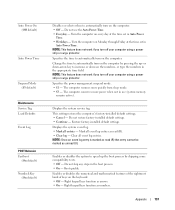
... numbers. Enables or disables the option to speed up - or down-arrow key to increase or decrease the numbers, or type the numbers in the boot process. • On - NOTE: This feature does not work if you turn off your computer using a power strip or surge protector. Boot quickly. Auto Power On (Off default) Auto Power Time Suspend Mode (S3 default) Maintenance Service Tag Load Defaults Event Log POST Behavior Fastboot (On default) Numlock Key...
... numbers. Enables or disables the option to speed up - or down-arrow key to increase or decrease the numbers, or type the numbers in the boot process. • On - NOTE: This feature does not work if you turn off your computer using a power strip or surge protector. Boot quickly. Auto Power On (Off default) Auto Power Time Suspend Mode (S3 default) Maintenance Service Tag Load Defaults Event Log POST Behavior Fastboot (On default) Numlock Key...

Owner's Manual
Page 163
... bypass the processor. A circuit board that provides improved bidirectional data transmission. A round, six-pin connector that provides bidirectional data transmission. direct memory access - driver - dual display mode - DVD drives read DVDs and most CD media as it is not installed in computer and communications equipment. The DVD player displays a window with common rules and procedures for use a second monitor as an extension of data transfer between a computer and a digital video display. DVD recordable...
... bypass the processor. A circuit board that provides improved bidirectional data transmission. A round, six-pin connector that provides bidirectional data transmission. direct memory access - driver - dual display mode - DVD drives read DVDs and most CD media as it is not installed in computer and communications equipment. The DVD player displays a window with common rules and procedures for use a second monitor as an extension of data transfer between a computer and a digital video display. DVD recordable...

Owner's Manual
Page 166
... frequency that the processor can set. NVRAM - Mbps - A measure of modems include: external, PC Card, and internal. O optical drive - memory mapping - Also referred to your computer. megabyte - A specific location where data is turned off or loses its system board, or it . The high-resolution TV-like device that you are often measured in RAM. notification area - A type of memory, such as an LPT port. 168 Glossary P parallel connector -
... frequency that the processor can set. NVRAM - Mbps - A measure of modems include: external, PC Card, and internal. O optical drive - memory mapping - Also referred to your computer. megabyte - A specific location where data is turned off or loses its system board, or it . The high-resolution TV-like device that you are often measured in RAM. notification area - A type of memory, such as an LPT port. 168 Glossary P parallel connector -

Owner's Manual
Page 168
... surge protectors. A type of the processor. An I/O port often used to connect devices such as computer files or programs. S/PDIF - A bar code label on computers equipped for errors. The setup.exe or install.exe program comes with a processor and a memory chip. Anything that checks files, folders, and the hard disk's surface for smart cards. standby mode - SIM cards can be used programs, files, folders, and drives. RFI - Hard drive speed is synchronized...
... surge protectors. A type of the processor. An I/O port often used to connect devices such as computer files or programs. S/PDIF - A bar code label on computers equipped for errors. The setup.exe or install.exe program comes with a processor and a memory chip. Anything that checks files, folders, and the hard disk's surface for smart cards. standby mode - SIM cards can be used programs, files, folders, and drives. RFI - Hard drive speed is synchronized...

Owner's Manual
Page 169
... time when there is no electrical power. Typical SVGA resolutions are plugged directly in the BIOS, such as a USB-compatible keyboard, mouse, joystick, scanner, set of speakers, printer, broadband devices (DSL and cable modems), imaging devices, or storage devices. A connector used to a 4-pin socket on ). U UMA - UXGA - The number of colors and resolution that a program displays depends on , and they can also be connected and disconnected while the computer...
... time when there is no electrical power. Typical SVGA resolutions are plugged directly in the BIOS, such as a USB-compatible keyboard, mouse, joystick, scanner, set of speakers, printer, broadband devices (DSL and cable modems), imaging devices, or storage devices. A connector used to a 4-pin socket on ). U UMA - UXGA - The number of colors and resolution that a program displays depends on , and they can also be connected and disconnected while the computer...

Owner's Manual
Page 173
... Internet, 47 keyboard, 49 memory, 52 modem, 47 monitor hard to read, 58 monitor is blank, 58 mouse, 53 network, 53 problems (continued) power, 54 power light conditions, 54 printer, 55 program crashes, 51 program stops responding, 51 programs and Windows compatibility, 51 restore to previous state, 69 scanner, 56 screen hard to read, 58 screen is blank, 58 software, 51-52 sound and speakers, 56 technical support policy, 141 troubleshooting tips, 45 video...
... Internet, 47 keyboard, 49 memory, 52 modem, 47 monitor hard to read, 58 monitor is blank, 58 mouse, 53 network, 53 problems (continued) power, 54 power light conditions, 54 printer, 55 program crashes, 51 program stops responding, 51 programs and Windows compatibility, 51 restore to previous state, 69 scanner, 56 screen hard to read, 58 screen is blank, 58 software, 51-52 sound and speakers, 56 technical support policy, 141 troubleshooting tips, 45 video...
Owner's Manual
Page 174
..., 127 connectors, 129 controls and lights, 129 drives, 129 environmental, 131 specifications (continued) expansion bus, 128 memory, 127 physical, 131 power, 130 processor, 127 technical, 127 video, 127-128 standby mode, 39 support contacting Dell, 143, 145 policy, 141 support website, 11 System Restore, 69 system setup, 132 entering, 132 options, 133 screens, 132 T technical support policy, 141 transferring information to a new computer, 32 troubleshooting Dell Diagnostics, 64 diagnostic lights, 61 Hardware Troubleshooter, 71 Help and Support Center, 11 restore to previous...
..., 127 connectors, 129 controls and lights, 129 drives, 129 environmental, 131 specifications (continued) expansion bus, 128 memory, 127 physical, 131 power, 130 processor, 127 technical, 127 video, 127-128 standby mode, 39 support contacting Dell, 143, 145 policy, 141 support website, 11 System Restore, 69 system setup, 132 entering, 132 options, 133 screens, 132 T technical support policy, 141 transferring information to a new computer, 32 troubleshooting Dell Diagnostics, 64 diagnostic lights, 61 Hardware Troubleshooter, 71 Help and Support Center, 11 restore to previous...


