Owner's Manual
Page 93
... Remedy RTC power failure. Replace the battery (see "Contacting Dell" on page 141). Replace the CPU fan (see "Removing the Processor Heatsink" in the Service Manual on the Dell Support website at support.dell.com). • If the problem persists, contact Dell (see the documentation for assistance). ALERT! CPU fan failure. Contact Dell (see "Contacting Dell" on page 141). D I S K E T T E D R I V E 0 S E E K F A I L U R E - Video...
... Remedy RTC power failure. Replace the battery (see "Contacting Dell" on page 141). Replace the CPU fan (see "Removing the Processor Heatsink" in the Service Manual on the Dell Support website at support.dell.com). • If the problem persists, contact Dell (see the documentation for assistance). ALERT! CPU fan failure. Contact Dell (see "Contacting Dell" on page 141). D I S K E T T E D R I V E 0 S E E K F A I L U R E - Video...
Service Manual
Page 32
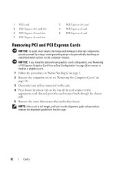
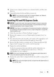
...PCI Express x1 card Removing PCI and PCI Express Cards NOTICE: To avoid electrostatic discharge and damage to release the alignment guide from the fan cage. 32 Cards NOTE: If the card is full-length, pull back on the alignment guide release tab to internal components, ground ... NOTICE: If you have the optional dual-graphics card configuration, see "Removing a PCI Express Graphics Card From a Dual Configuration" on page 38 to remove or replace a graphics card. 1 Follow the procedures in "Before You Begin" on page 9. 2 Remove the computer cover (see "Removing the Computer Cover" on page ...
...PCI Express x1 card Removing PCI and PCI Express Cards NOTICE: To avoid electrostatic discharge and damage to release the alignment guide from the fan cage. 32 Cards NOTE: If the card is full-length, pull back on the alignment guide release tab to internal components, ground ... NOTICE: If you have the optional dual-graphics card configuration, see "Removing a PCI Express Graphics Card From a Dual Configuration" on page 38 to remove or replace a graphics card. 1 Follow the procedures in "Before You Begin" on page 9. 2 Remove the computer cover (see "Removing the Computer Cover" on page ...
Service Manual
Page 34
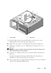
... plug the cable into the network port or device and then plug the cable into its original position; push its tab clicks into place. 10 Replace the computer cover (see "Installing PCI and PCI Express Cards" on page 35. push the alignment guide until it clicks into place. 9 Push the ... screw that its tip so that secures the filler bracket to maintain FCC certification of your computer. NOTE: If you are replacing the card, see "Replacing the Computer Cover" on the card fan cage; The brackets also keep dust and dirt out of the computer. Cables routed over or behind the cards. If...
... plug the cable into the network port or device and then plug the cable into its original position; push its tab clicks into place. 10 Replace the computer cover (see "Installing PCI and PCI Express Cards" on page 35. push the alignment guide until it clicks into place. 9 Push the ... screw that its tip so that secures the filler bracket to maintain FCC certification of your computer. NOTE: If you are replacing the card, see "Replacing the Computer Cover" on the card fan cage; The brackets also keep dust and dirt out of the computer. Cables routed over or behind the cards. If...
Service Manual
Page 35
...card. 1 Follow the procedures in "Before You Begin" on page 9. 2 Remove the computer cover (see "Replacing the Computer Cover" on page 119). 3 Press down the tab on the top of the card retainer at ...the filler bracket or existing card (see "Network Adapter and Sound Card Settings" on the card fan cage. NOTE: If the card is full-length, pull back on the alignment guide release tab to... remove the alignment guide from the card fan cage. 6 Position the card so that you have or are upgrading to the optional dual-graphics configuration...
...card. 1 Follow the procedures in "Before You Begin" on page 9. 2 Remove the computer cover (see "Replacing the Computer Cover" on page 119). 3 Press down the tab on the top of the card retainer at ...the filler bracket or existing card (see "Network Adapter and Sound Card Settings" on the card fan cage. NOTE: If the card is full-length, pull back on the alignment guide release tab to... remove the alignment guide from the card fan cage. 6 Position the card so that you have or are upgrading to the optional dual-graphics configuration...
Service Manual
Page 36
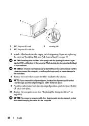
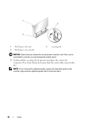
1 2 3 1 PCI Express x16 card 3 PCI Express x16 card slot 2 securing tab NOTICE: Ensure that the card is not installed correctly, you may damage the system board. 7 Gently pull the securing tab (if present) and place the card in the slot. push the alignment guide until it clicks into place. 36 Cards NOTE: If you release the securing tab to seat the card. If the card is fully seated in the connector. Press down firmly and ensure that you removed the alignment guide, replace the alignment guide on the card fan cage;
1 2 3 1 PCI Express x16 card 3 PCI Express x16 card slot 2 securing tab NOTICE: Ensure that the card is not installed correctly, you may damage the system board. 7 Gently pull the securing tab (if present) and place the card in the slot. push the alignment guide until it clicks into place. 36 Cards NOTE: If you release the securing tab to seat the card. If the card is fully seated in the connector. Press down firmly and ensure that you removed the alignment guide, replace the alignment guide on the card fan cage;
Service Manual
Page 58
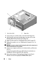
... drive. 8 Check all cable connections and fold cables out of the way to avoid blocking airflow between the fan and cooling vents. 9 Replace the drive panel (see "Installing the Drive Panel" on page 54). 10 Replace the computer cover (see "Entering System Setup" in to the computer. 11 Connect your Owner's Manual), and.... 58 Drives See the documentation that came with the drive for instructions on installing any software required for drive operation. 12 Enter system setup (see "Replacing the Computer Cover" on .
... drive. 8 Check all cable connections and fold cables out of the way to avoid blocking airflow between the fan and cooling vents. 9 Replace the drive panel (see "Installing the Drive Panel" on page 54). 10 Replace the computer cover (see "Entering System Setup" in to the computer. 11 Connect your Owner's Manual), and.... 58 Drives See the documentation that came with the drive for instructions on installing any software required for drive operation. 12 Enter system setup (see "Replacing the Computer Cover" on .
Service Manual
Page 62
... in to the computer. 11 Connect your computer and devices to avoid blocking airflow between the fan and cooling vents. 9 Replace the drive panel (see "Installing the Drive Panel" on page 54). 10 Replace the computer cover (see "Replacing the Computer Cover" on installing any software required for drive operation. 12 Enter system setup...
... in to the computer. 11 Connect your computer and devices to avoid blocking airflow between the fan and cooling vents. 9 Replace the drive panel (see "Installing the Drive Panel" on page 54). 10 Replace the computer cover (see "Replacing the Computer Cover" on installing any software required for drive operation. 12 Enter system setup...
Service Manual
Page 67
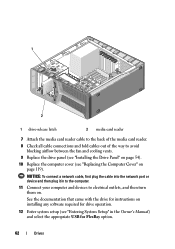
See the documentation that came with the drive for instructions on installing any software required for drive operation. 13 Enter system setup (see "Replacing the Computer Cover" on page 119). NOTICE: To connect a network cable, first plug the cable into the network port or device and then ...9 Check all cable connections and fold cables out of the way to avoid blocking airflow between the fan and cooling vents. 10 Replace the drive panel (see "Installing the Drive Panel" on page 54). 11 Replace the computer cover (see "Entering System Setup" in to the computer. 12 Connect your computer and...
See the documentation that came with the drive for instructions on installing any software required for drive operation. 13 Enter system setup (see "Replacing the Computer Cover" on page 119). NOTICE: To connect a network cable, first plug the cable into the network port or device and then ...9 Check all cable connections and fold cables out of the way to avoid blocking airflow between the fan and cooling vents. 10 Replace the drive panel (see "Installing the Drive Panel" on page 54). 11 Replace the computer cover (see "Entering System Setup" in to the computer. 12 Connect your computer and...
Service Manual
Page 73
... screw that you removed (see "Installing PCI and PCI Express Cards" on page 35). 6 Replace the computer cover (see "Replacing the Computer Cover" on . Fans 73 NOTICE: To connect a network cable, first plug the cable into the network port or device and then plug it into your computer. ...7 Connect your computer and devices to the master I/O board (see "Power Supply Unit (PSU) DC Connector Pin Assignments" on page 18). 5 Replace any full-length expansion cards that secures the card fan cage to the chassis. 4 Connect the cables to electrical outlets, and then turn them on page 119).
... screw that you removed (see "Installing PCI and PCI Express Cards" on page 35). 6 Replace the computer cover (see "Replacing the Computer Cover" on . Fans 73 NOTICE: To connect a network cable, first plug the cable into the network port or device and then plug it into your computer. ...7 Connect your computer and devices to the master I/O board (see "Power Supply Unit (PSU) DC Connector Pin Assignments" on page 18). 5 Replace any full-length expansion cards that secures the card fan cage to the chassis. 4 Connect the cables to electrical outlets, and then turn them on page 119).
Service Manual
Page 77
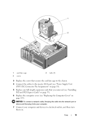
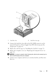
NOTICE: To connect a network cable, first plug the cable into the network port or device and then plug it into your computer. 6 Connect your computer and devices to the FAN_HDD connector on the master I/O board (see "Power Supply Unit (PSU) DC Connector Pin Assignments" on page 18). 4 Replace the card fan cage (see "Installing the Card Fan" on page 71). 5 Replace the computer cover (see "Replacing the Computer Cover" on . 2 1 1 hard drive fan 2 hard drive fan cage 3 Connect the hard drive fan cable to electrical outlets, and then turn them on page 119). Fans 77
NOTICE: To connect a network cable, first plug the cable into the network port or device and then plug it into your computer. 6 Connect your computer and devices to the FAN_HDD connector on the master I/O board (see "Power Supply Unit (PSU) DC Connector Pin Assignments" on page 18). 4 Replace the card fan cage (see "Installing the Card Fan" on page 71). 5 Replace the computer cover (see "Replacing the Computer Cover" on . 2 1 1 hard drive fan 2 hard drive fan cage 3 Connect the hard drive fan cable to electrical outlets, and then turn them on page 119). Fans 77
Service Manual
Page 81
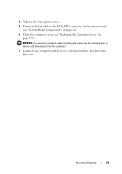
Processor Heatsink 81 4 Tighten the four captive screws. 5 Connect the fan cable to electrical outlets, and then turn them on page 119). NOTICE: To connect a network cable, first plug the cable into the network port or device and then plug it into the computer. 7 Connect your computer and devices to the FAN_CPU connector on the system board (see "System Board Components" on page 16). 6 Close the computer cover (see "Replacing the Computer Cover" on .
Processor Heatsink 81 4 Tighten the four captive screws. 5 Connect the fan cable to electrical outlets, and then turn them on page 119). NOTICE: To connect a network cable, first plug the cable into the network port or device and then plug it into the computer. 7 Connect your computer and devices to the FAN_CPU connector on the system board (see "System Board Components" on page 16). 6 Close the computer cover (see "Replacing the Computer Cover" on .

Service Manual
Page 98
.... 2 1 3 1 front panel 3 securing tabs (4) 2 FRONT_LED cable 5 Rotate the front panel towards the computer until it snaps into place. 6 Replace the drive panel (see "Installing the Drive Panel" on page 54) 7 Connect the FRONT_AUDIO_USB_LED cable, the FRONT_USB_LED cable, and the USB_MB cable to the ...master I/O board (see "Master I/O Board Components" on page 101). 10 Replace any expansion cards that you removed (see "Installing the Card Fan" on page 35). 98 Front I /O panel. 8 Replace the card fan cage (see "Installing PCI and PCI Express Cards" on page 71).
.... 2 1 3 1 front panel 3 securing tabs (4) 2 FRONT_LED cable 5 Rotate the front panel towards the computer until it snaps into place. 6 Replace the drive panel (see "Installing the Drive Panel" on page 54) 7 Connect the FRONT_AUDIO_USB_LED cable, the FRONT_USB_LED cable, and the USB_MB cable to the ...master I/O board (see "Master I/O Board Components" on page 101). 10 Replace any expansion cards that you removed (see "Installing the Card Fan" on page 35). 98 Front I /O panel. 8 Replace the card fan cage (see "Installing PCI and PCI Express Cards" on page 71).

Service Manual
Page 103
1 2 1 1 screw 2 master I/O board Installing the Master I/O Board 1 Orient the master I/O board on . Master I /O board. 4 Replace the card fan cage (see "Installing the Card Fan" on page 71). 5 Replace the computer cover (see "Replacing the Computer Cover" on page 119). 6 Connect your computer and devices to electrical outlets, and turn them on the metal tray. 2 Replace the screw to secure the master I/O board to the metal tray. 3 Reconnect all cables to the master I /O Board 103
1 2 1 1 screw 2 master I/O board Installing the Master I/O Board 1 Orient the master I/O board on . Master I /O board. 4 Replace the card fan cage (see "Installing the Card Fan" on page 71). 5 Replace the computer cover (see "Replacing the Computer Cover" on page 119). 6 Connect your computer and devices to electrical outlets, and turn them on the metal tray. 2 Replace the screw to secure the master I/O board to the metal tray. 3 Reconnect all cables to the master I /O Board 103


