Owner's Manual
Page 15
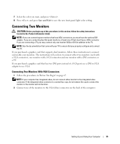
... integrated video connector. The instructions tell you purchased a graphics card that supports dual monitors, follow the safety instructions located in "Before You Begin" on the back of the computer. Setting Up and Using Your Computer 15 Connecting Two Monitors With VGA Connectors 1 Follow the procedures in the Product Information Guide. If you are connecting two flat-panel monitors, at least one monitor (VGA or DVI) in this section, follow these instructions to connect and enable...
... integrated video connector. The instructions tell you purchased a graphics card that supports dual monitors, follow the safety instructions located in "Before You Begin" on the back of the computer. Setting Up and Using Your Computer 15 Connecting Two Monitors With VGA Connectors 1 Follow the procedures in the Product Information Guide. If you are connecting two flat-panel monitors, at least one monitor (VGA or DVI) in this section, follow these instructions to connect and enable...
Owner's Manual
Page 17
... monitors display the same image. • In extended desktop mode, you connect the monitor(s) or TV, turn on the hard drive. See "Hard Drive" on page 90 for its Dimension computers. For information on page 24). A RAID level 0 configuration is recommended for the data integrity requirements of space inside the chassis. • Compact cable connectors save space on the system board and on the computer. The Intel RAID controller on serial ATA drive connections. A RAID...
... monitors display the same image. • In extended desktop mode, you connect the monitor(s) or TV, turn on the hard drive. See "Hard Drive" on page 90 for its Dimension computers. For information on page 24). A RAID level 0 configuration is recommended for the data integrity requirements of space inside the chassis. • Compact cable connectors save space on the system board and on the computer. The Intel RAID controller on serial ATA drive connections. A RAID...
Owner's Manual
Page 50
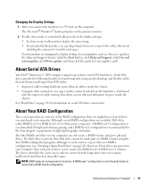
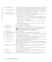
... Solving Problems C H E C K T H E D I A G N O S T I C L I T O R - Fans, fluorescent lights, halogen lamps, and other electrical devices can cause the screen image to appear "shaky." CHECK THE MONITOR CABLE CONNECTION - • Ensure that the graphics cable is connected as a lamp. Ensure that the monitor is turned on the setup diagram for your speaker system includes a subwoofer, ensure that the subwoofer is at least 60 cm (2 ft) away from the monitor. If the power light is blinking, press a key...
... Solving Problems C H E C K T H E D I A G N O S T I C L I T O R - Fans, fluorescent lights, halogen lamps, and other electrical devices can cause the screen image to appear "shaky." CHECK THE MONITOR CABLE CONNECTION - • Ensure that the graphics cable is connected as a lamp. Ensure that the monitor is turned on the setup diagram for your speaker system includes a subwoofer, ensure that the subwoofer is at least 60 cm (2 ft) away from the monitor. If the power light is blinking, press a key...
Owner's Manual
Page 55
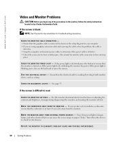
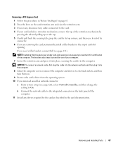
... all modules without error. • If available, install properly working memory of the same type into your computer (see page 76). • If the problem persists, contact Dell (see page 131). If the computer starts normally, troubleshoot the last card removed from the computer for each card. Advanced Troubleshooting 55 A possible expansion card failure has occurred. 1 Determine if a conflict exists by removing a card (not a graphics card) and restarting the...
... all modules without error. • If available, install properly working memory of the same type into your computer (see page 76). • If the problem persists, contact Dell (see page 131). If the computer starts normally, troubleshoot the last card removed from the computer for each card. Advanced Troubleshooting 55 A possible expansion card failure has occurred. 1 Determine if a conflict exists by removing a card (not a graphics card) and restarting the...

Owner's Manual
Page 60
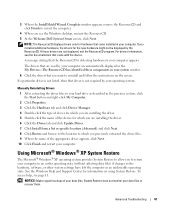
... with the previously installed version. 1 Click the Start button and click Control Panel. 2 Under Pick a Category, click Performance and Maintenance. 3 Click System. 4 In the System Properties window, click the Hardware tab. 5 Click Device Manager. 6 Right-click the device for Dell™ computers. If you install or update a driver, use Windows XP Device Driver Rollback to replace the driver with a [!]) on the screen. 60 Advanced Troubleshooting If Device Driver Rollback does not resolve the problem, then use the ResourceCD...
... with the previously installed version. 1 Click the Start button and click Control Panel. 2 Under Pick a Category, click Performance and Maintenance. 3 Click System. 4 In the System Properties window, click the Hardware tab. 5 Click Device Manager. 6 Right-click the device for Dell™ computers. If you install or update a driver, use Windows XP Device Driver Rollback to replace the driver with a [!]) on the screen. 60 Advanced Troubleshooting If Device Driver Rollback does not resolve the problem, then use the ResourceCD...
Owner's Manual
Page 61
... the screen. Using Microsoft® Windows® XP System Restore The Microsoft® Windows® XP operating system provides System Restore to allow you want to return your data files. For drivers information, see the documentation that came with the device. To access help, see the Windows desktop, reinsert the ResourceCD. 5 At the Welcome Dell System Owner screen, click Next. See the Windows Help and Support Center for hardware that came installed...
... the screen. Using Microsoft® Windows® XP System Restore The Microsoft® Windows® XP operating system provides System Restore to allow you want to return your data files. For drivers information, see the documentation that came with the device. To access help, see the Windows desktop, reinsert the ResourceCD. 5 At the Welcome Dell System Owner screen, click Next. See the Windows Help and Support Center for hardware that came installed...

Owner's Manual
Page 62
... Advanced Troubleshooting The Restoration Complete screen appears after you to resolve the problem. If a calendar date has only one restore point, then that is automatically selected. If two or more restore points are available, click the restore point that allows you install a device driver, use System Restore. www.dell.com | support.dell.com Creating a Restore Point 1 Click the Start button and click Help and Support. 2 Click System Restore. 3 Follow the instructions...
... Advanced Troubleshooting The Restoration Complete screen appears after you to resolve the problem. If a calendar date has only one restore point, then that is automatically selected. If two or more restore points are available, click the restore point that allows you install a device driver, use System Restore. www.dell.com | support.dell.com Creating a Restore Point 1 Click the Start button and click Help and Support. 2 Click System Restore. 3 Follow the instructions...
Owner's Manual
Page 72
... Surround connector - Turn off the computer and any installed PCI cards (four slots) and PCI Express cards (one x16 slot and one x1 slot). 19 power supply fans For optimal cooling, two power supply fans are provided. If your monitor has a VGA connector, plug it into the VGA connector on the computer. 6 VGA video connector If your monitor has a DVI connector, plug it into the network connector. 11 power connector Insert the power cable. 12 serial connector (COM 1) Connect a serial device, such as a handheld device, to the serial port. 13 parallel connector Connect a parallel device...
... Surround connector - Turn off the computer and any installed PCI cards (four slots) and PCI Express cards (one x16 slot and one x1 slot). 19 power supply fans For optimal cooling, two power supply fans are provided. If your monitor has a VGA connector, plug it into the VGA connector on the computer. 6 VGA video connector If your monitor has a DVI connector, plug it into the network connector. 11 power connector Insert the power cable. 12 serial connector (COM 1) Connect a serial device, such as a handheld device, to the serial port. 13 parallel connector Connect a parallel device...
Owner's Manual
Page 87
... connect a network cable, first plug the cable into the network wall jack and then plug it into the computer. 8 Close the computer cover, reconnect the computer and devices to electrical outlets, and then turn them on. 9 Remove the card's driver from the operating system. 10 If you removed an add-in network connector: a Enter system setup (see page 131). If you are removing the card permanently, install a filler bracket in the empty card-slot opening. Removing and Installing Parts...
... connect a network cable, first plug the cable into the network wall jack and then plug it into the computer. 8 Close the computer cover, reconnect the computer and devices to electrical outlets, and then turn them on. 9 Remove the card's driver from the operating system. 10 If you removed an add-in network connector: a Enter system setup (see page 131). If you are removing the card permanently, install a filler bracket in the empty card-slot opening. Removing and Installing Parts...
Owner's Manual
Page 95
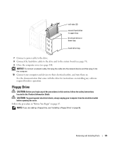
... the safety instructions located in the Product Information Guide. Removing and Installing Parts 95 See the documentation that came with the drive for drive operation. rail tabs (2) second hard drive in upper bay first hard drive in lower bay hard drive bay 7 Connect a power cable to the drive. 8 Connect the hard-drive cable to the drive and to their electrical outlets, and turn them on. NOTICE: To connect a network cable, first plug the cable into the network device and then plug it into...
... the safety instructions located in the Product Information Guide. Removing and Installing Parts 95 See the documentation that came with the drive for drive operation. rail tabs (2) second hard drive in upper bay first hard drive in lower bay hard drive bay 7 Connect a power cable to the drive. 8 Connect the hard-drive cable to the drive and to their electrical outlets, and turn them on. NOTICE: To connect a network cable, first plug the cable into the network device and then plug it into...
Owner's Manual
Page 124
... hard drive when the diagnostic tests are booting to a USB device, connect the USB device to a USB connector (see page 119). 1 If you to specify the function keys to boot from the floppy drive. To make sure that you must be bootable. Insert the memory device into a USB port and restart the computer. You can run the Dell Diagnostics on the Dell Dimension ResourceCD, but you want the computer to On (default), this option activates the cursor-control...
... hard drive when the diagnostic tests are booting to a USB device, connect the USB device to a USB connector (see page 119). 1 If you to specify the function keys to boot from the floppy drive. To make sure that you must be bootable. Insert the memory device into a USB port and restart the computer. You can run the Dell Diagnostics on the Dell Dimension ResourceCD, but you want the computer to On (default), this option activates the cursor-control...

Owner's Manual
Page 150
...95 drives (continued) removing hard drive, 90 second hard drive, 94 serial ATA, 90 DVD drive problems, 38 DVDs copying, 28 playing, 26 DVI connector, 72 E e-mail problems, 39 End User License Agreement, 10 ergonomics information, 10 error messages, 40 diagnostic lights, 53 F fans power supply, 72 processor, 71 Files and Settings Transfer Wizard, 26 Finding Information, 9 floppy drive installing, 96 removing, 95 H hard drive activity light, 69 installing, 91 installing second, 94 problems, 39 removing, 90 hardware Dell Diagnostics, 56 drives, RAID configuration, 17 Hardware Troubleshooter, 64...
...95 drives (continued) removing hard drive, 90 second hard drive, 94 serial ATA, 90 DVD drive problems, 38 DVDs copying, 28 playing, 26 DVI connector, 72 E e-mail problems, 39 End User License Agreement, 10 ergonomics information, 10 error messages, 40 diagnostic lights, 53 F fans power supply, 72 processor, 71 Files and Settings Transfer Wizard, 26 Finding Information, 9 floppy drive installing, 96 removing, 95 H hard drive activity light, 69 installing, 91 installing second, 94 problems, 39 removing, 90 hardware Dell Diagnostics, 56 drives, RAID configuration, 17 Hardware Troubleshooter, 64...
Owner's Manual
Page 151
... connect two, 15-16 connect VGA, 15-16 display settings, 17 extended desktop mode, 17 hard to read, 50 problems, 50 motherboard. See system board mouse connector, 72 problems, 44 N network connector, 71 Network Setup Wizard, 30 problems, 45 Network Setup Wizard, 30 O operating system CD, 11 reinstalling, 11 reinstalling Windows XP, 64 Operating System CD, 11 overclocking, 35 P password clearing, 126 jumper, 126 PCI cards installing, 80 removing, 82 PCI Express cards installing, 84 removing, 87 performance overclocking, 35 playing CDs, 26 playing DVDs, 26 power button, 69 connector...
... connect two, 15-16 connect VGA, 15-16 display settings, 17 extended desktop mode, 17 hard to read, 50 problems, 50 motherboard. See system board mouse connector, 72 problems, 44 N network connector, 71 Network Setup Wizard, 30 problems, 45 Network Setup Wizard, 30 O operating system CD, 11 reinstalling, 11 reinstalling Windows XP, 64 Operating System CD, 11 overclocking, 35 P password clearing, 126 jumper, 126 PCI cards installing, 80 removing, 82 PCI Express cards installing, 84 removing, 87 performance overclocking, 35 playing CDs, 26 playing DVDs, 26 power button, 69 connector...

Owner's Manual
Page 152
... monitor serial connectors, 72 serial ATA, 90 Service Tag, 10 settings system setup, 119 Setup Diagram, 10 software Hyper-Threading, 35 problems, 42-43 sound problems, 48 volume, 48 sound connectors, 72 speaker problems, 48 volume, 48 specifications computer information, 115 connectors, 117 controls and lights, 117 drives, 116 environmental, 119 expansion bus, 116 memory, 115 physical, 118 power, 118 processor, 115 technical, 115 video, 115 standby mode, 31 support contacting Dell, 129 policy, 127 support website, 11 system board, 75 system board...
... monitor serial connectors, 72 serial ATA, 90 Service Tag, 10 settings system setup, 119 Setup Diagram, 10 software Hyper-Threading, 35 problems, 42-43 sound problems, 48 volume, 48 sound connectors, 72 speaker problems, 48 volume, 48 specifications computer information, 115 connectors, 117 controls and lights, 117 drives, 116 environmental, 119 expansion bus, 116 memory, 115 physical, 118 power, 118 processor, 115 technical, 115 video, 115 standby mode, 31 support contacting Dell, 129 policy, 127 support website, 11 system board, 75 system board...

Service Manual
Page 11
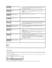
... responding, see "Diagnostic Lights." l If the power light is blinking green, the computer is securely connected to the system board. Back to Contents Page Advanced Troubleshooting Dell™ Dimension™ XPS Service Manual Power Lights Diagnostic Lights Beep Codes System Messages Power Lights CAUTION: Before you begin any of the procedures in this section, follow the safety instructions located in a normal off or is not receiving power. ¡ Reseat the power cable into both the power connector on .
... responding, see "Diagnostic Lights." l If the power light is blinking green, the computer is securely connected to the system board. Back to Contents Page Advanced Troubleshooting Dell™ Dimension™ XPS Service Manual Power Lights Diagnostic Lights Beep Codes System Messages Power Lights CAUTION: Before you begin any of the procedures in this section, follow the safety instructions located in a normal off or is not receiving power. ¡ Reseat the power cable into both the power connector on .
Service Manual
Page 12
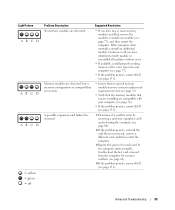
... for instructions on your screen identifying a problem with your Owner's Manual for the devices installed on obtaining technical assistance. Reseating the memory modules may fix the beep code errors in a normal operating condition after POST. l If the problem still exists, install a graphics card that no special memory module/memory connector placement requirements exist. l If available, install properly working memory of the same type into your computer. If the problem persists, contact Dell. Memory modules are detected, but a memory configuration...
... for instructions on your screen identifying a problem with your Owner's Manual for the devices installed on obtaining technical assistance. Reseating the memory modules may fix the beep code errors in a normal operating condition after POST. l If the problem still exists, install a graphics card that no special memory module/memory connector placement requirements exist. l If available, install properly working memory of the same type into your computer. If the problem persists, contact Dell. Memory modules are detected, but a memory configuration...

Service Manual
Page 15
Back to Contents Page System Setup Program Dell™ Dimension™ XPS Service Manual Overview Entering the System Setup Program System Setup Program Screens System Setup Program Options Boot Sequence Clearing Forgotten Passwords Clearing CMOS Settings Overview Use the system setup program as follows: l To change the system configuration information after you add, change, or remove any hardware in this list. Certain changes can view your current settings and make changes to your settings. System Setup Program Screens The system setup program screen displays current or changeable ...
Back to Contents Page System Setup Program Dell™ Dimension™ XPS Service Manual Overview Entering the System Setup Program System Setup Program Screens System Setup Program Options Boot Sequence Clearing Forgotten Passwords Clearing CMOS Settings Overview Use the system setup program as follows: l To change the system configuration information after you add, change, or remove any hardware in this list. Certain changes can view your current settings and make changes to your settings. System Setup Program Screens The system setup program screen displays current or changeable ...
Service Manual
Page 16
... Options List. USB Set to On (default) so that access to the system can set the NIC to the computer's system setup program in the same way that USB devices will appear in the operating system. 1394 Controller Enable or disable the internal 1394 controller. Auto, the default setting, automatically configures a connector to clear the intrusion message. Performance HyperThreading If your computer's processor supports Hyper-Threading, this option will be Admin Password restricted with the setup password...
... Options List. USB Set to On (default) so that access to the system can set the NIC to the computer's system setup program in the same way that USB devices will appear in the operating system. 1394 Controller Enable or disable the internal 1394 controller. Auto, the default setting, automatically configures a connector to clear the intrusion message. Performance HyperThreading If your computer's processor supports Hyper-Threading, this option will be Admin Password restricted with the setup password...
Service Manual
Page 17
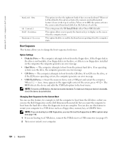
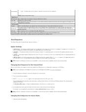
... the screen when the computer starts. Changing Boot Sequence for most components NOTE: System memory remains active. Maintenance CMOS Defaults This setting restores the computer's factory-installed default settings. The options are booting to a USB device, connect the USB device to On (default), your keyboard. POST Hotkeys This option allows you are booting to display on the drive, the computer generates an error message. l Hard Drive - l CD Drive - If you must first set to change the boot sequence for the current boot only. The Boot Device Menu appears, listing...
... the screen when the computer starts. Changing Boot Sequence for most components NOTE: System memory remains active. Maintenance CMOS Defaults This setting restores the computer's factory-installed default settings. The options are booting to a USB device, connect the USB device to On (default), your keyboard. POST Hotkeys This option allows you are booting to display on the drive, the computer generates an error message. l Hard Drive - l CD Drive - If you must first set to change the boot sequence for the current boot only. The Boot Device Menu appears, listing...

Setup Diagram
Page 2
... 1394 connector USB 2.0 connectors (2) sound-card connectors Help and Support To view your Owner's Manual: Double-click the owner's manual icon on your computer: • Click the Start button and click Help and Support. • For help with the Windows operating system, click Microsoft Windows XP Tips. All rights reserved. Printed in the marks and names of Dell Inc.; Microsoft and Windows are trademarks of others. For other devices according to change...
... 1394 connector USB 2.0 connectors (2) sound-card connectors Help and Support To view your Owner's Manual: Double-click the owner's manual icon on your computer: • Click the Start button and click Help and Support. • For help with the Windows operating system, click Microsoft Windows XP Tips. All rights reserved. Printed in the marks and names of Dell Inc.; Microsoft and Windows are trademarks of others. For other devices according to change...


