Handling swollen Lithium-ion batteries
Page 1
...to malfunction, discontinue the use a battery from the system. We recommend contacting Dell product support for options to work with your Dell computer. When the system will no longer power on battery power. Do not use of the applicable warranty or service contract, including options for...fire or explosion. To discharge the battery, unplug the AC adapter from Dell. 1 Lithium-ion polymer batteries have increased in popularity in recent years and have become standard in an approved shipping container (provided by Dell), to customer preferences for a slim form factor (especially ...
...to malfunction, discontinue the use a battery from the system. We recommend contacting Dell product support for options to work with your Dell computer. When the system will no longer power on battery power. Do not use of the applicable warranty or service contract, including options for...fire or explosion. To discharge the battery, unplug the AC adapter from Dell. 1 Lithium-ion polymer batteries have increased in popularity in recent years and have become standard in an approved shipping container (provided by Dell), to customer preferences for a slim form factor (especially ...
Quick Start Guide
Page 2
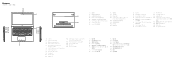
... 1. カメラ 2 3 4. HDMI ポート 12. Noble security-cable slot 5. Power‑adapter port 15. HDMI 連接埠 12. Noble 5 6. Noble security 5 6. USB 3.1 第 1 代 (Type-C 備 Power Delivery/DisplayPort 功能) 13 14 15. 喇叭 16 Power button with optional fingerprint reader 6. USB 3.1 Gen 1 PowerShare) 7. USB 3.1 Gen 1 ポ...
... 1. カメラ 2 3 4. HDMI ポート 12. Noble security-cable slot 5. Power‑adapter port 15. HDMI 連接埠 12. Noble 5 6. Noble security 5 6. USB 3.1 第 1 代 (Type-C 備 Power Delivery/DisplayPort 功能) 13 14 15. 喇叭 16 Power button with optional fingerprint reader 6. USB 3.1 Gen 1 PowerShare) 7. USB 3.1 Gen 1 ポ...

Ownerss Manual
Page 5
... Keyboard...48 Touchpad specification...48 Camera...48 Storage specification...48 Battery specification...48 AC adapter...49 Physical specification...50 Environmental specification...50 5 System setup...51 Boot menu...51 ...54 Security...55 Secure boot...57 Intel Software Guard Extensions options...57 Performance...58 Power management...59 Post behavior...60 Virtualization support...61 Wireless options...61 Maintenance...61 ...BitLocker enabled 63 Updating your system BIOS using a USB flash drive 63 Updating the Dell BIOS in Linux and Ubuntu environments 64 Flashing the BIOS from the F12 One-Time...
... Keyboard...48 Touchpad specification...48 Camera...48 Storage specification...48 Battery specification...48 AC adapter...49 Physical specification...50 Environmental specification...50 5 System setup...51 Boot menu...51 ...54 Security...55 Secure boot...57 Intel Software Guard Extensions options...57 Performance...58 Power management...59 Post behavior...60 Virtualization support...61 Wireless options...61 Maintenance...61 ...BitLocker enabled 63 Updating your system BIOS using a USB flash drive 63 Updating the Dell BIOS in Linux and Ubuntu environments 64 Flashing the BIOS from the F12 One-Time...

Ownerss Manual
Page 23
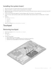
c Remove the two M2.0 x 5 screws that secure the USB Type C port bracket to the system board [3]. Removing and installing components 23 d Lift the USB Type C port bracket away from the connector. e solid-state drive(SSD) 3 To remove the system board: a Disconnect the following cables: • Input output(I/O) board cable [1,2] • Keyboard backlight cable [3] • Keyboard and Touchpad cable [4] b Disconnect the eDP cable [1], power adapter port cable [2] and speaker cable [5] from the system [4].
c Remove the two M2.0 x 5 screws that secure the USB Type C port bracket to the system board [3]. Removing and installing components 23 d Lift the USB Type C port bracket away from the connector. e solid-state drive(SSD) 3 To remove the system board: a Disconnect the following cables: • Input output(I/O) board cable [1,2] • Keyboard backlight cable [3] • Keyboard and Touchpad cable [4] b Disconnect the eDP cable [1], power adapter port cable [2] and speaker cable [5] from the system [4].
Ownerss Manual
Page 25
... C bracket with the screw holes on the system board and replace the two screws to secure the bracket to the system. 4 Connect the eDP cable, power adapter port cable and speaker cable to the connector in the system board. 5 Connect the Input output board cable, speaker cable, keyboard backlight cable, keyboard cable...
... C bracket with the screw holes on the system board and replace the two screws to secure the bracket to the system. 4 Connect the eDP cable, power adapter port cable and speaker cable to the connector in the system board. 5 Connect the Input output board cable, speaker cable, keyboard backlight cable, keyboard cable...
Ownerss Manual
Page 34
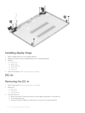
b Lift the hinge bracket [2]. DC-in Removing the DC-in 1 Follow the procedure in Before working inside your computer. c Disconnect the power-adapter port cable from the connector in the system board [3]. 34 Removing and installing components Installing display hinge 1 Place the display hinge cover on the display ...
b Lift the hinge bracket [2]. DC-in Removing the DC-in 1 Follow the procedure in Before working inside your computer. c Disconnect the power-adapter port cable from the connector in the system board [3]. 34 Removing and installing components Installing display hinge 1 Place the display hinge cover on the display ...
Ownerss Manual
Page 35
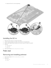
... procedure in Before working inside your computer. Installing the DC-in 1 Place and connect the DC-in to its slot in the system. 2 Connect the power-adapter port cable to the connector in the system board. 3 Place the right display hinge and replace the 3 screws to secure the hinge to the system...
... procedure in Before working inside your computer. Installing the DC-in 1 Place and connect the DC-in to its slot in the system. 2 Connect the power-adapter port cable to the connector in the system board. 3 Place the right display hinge and replace the 3 screws to secure the hinge to the system...

Ownerss Manual
Page 43
...; USB 3.0/USB 3.1 Gen 1 RAIDs • Optical Media Drives • Multimedia Devices • Networking • USB 3.0/USB 3.1 Gen 1 Adapter Cards & Hubs Compatibility The good news is a single connector standard that single USB port Technology and components 43 Microsoft announced that 's very small. ... below are some products that previously weren't USB territory, like USB 3.1 and USB power delivery (USB PD). With its immediate release, but in Windows 7, SuperSpeed support would have adapters that USB 3.0/USB 3.1 Gen 1 has been carefully planned from a maximum resolution,...
...; USB 3.0/USB 3.1 Gen 1 RAIDs • Optical Media Drives • Multimedia Devices • Networking • USB 3.0/USB 3.1 Gen 1 Adapter Cards & Hubs Compatibility The good news is a single connector standard that single USB port Technology and components 43 Microsoft announced that 's very small. ... below are some products that previously weren't USB territory, like USB 3.1 and USB power delivery (USB PD). With its immediate release, but in Windows 7, SuperSpeed support would have adapters that USB 3.0/USB 3.1 Gen 1 has been carefully planned from a maximum resolution,...

Ownerss Manual
Page 59
Power Management Option AC Behavior Description Allows you to enable USB devices to wake the system from turning on automatically when an AC adapter is connected. • Wake on automatically. USB Wake Support Allows you to enable or disable the computer from standby. • ...Speed Shift Technology. • Enabled-Default Auto On Time Allows you to select the charging mode for all the batteries. The options are : • Adaptive-Default • Standard - System setup 59 The options are : • Disabled-Default • Every Day • Weekdays • Select Days This...
Power Management Option AC Behavior Description Allows you to enable USB devices to wake the system from turning on automatically when an AC adapter is connected. • Wake on automatically. USB Wake Support Allows you to enable or disable the computer from standby. • ...Speed Shift Technology. • Enabled-Default Auto On Time Allows you to select the charging mode for all the batteries. The options are : • Adaptive-Default • Standard - System setup 59 The options are : • Disabled-Default • Every Day • Weekdays • Select Days This...

Ownerss Manual
Page 60
... Fn Lock Options Description Allows you to enable or disable the system setup (BIOS) warning messages when you use certain power adapters. • Enable Adapter Warnings-Default Allows you to indicate during the POST process. Sign of the following options: • Prompt on Warnings and Errors-Default ...system to speed up the boot process by turning on errors, or continue when either warnings or errors are detected during POST that the power button press has been acknowledged by bypassing some of F1-F12, between their standard and secondary functions. If you disable this option, ...
... Fn Lock Options Description Allows you to enable or disable the system setup (BIOS) warning messages when you use certain power adapters. • Enable Adapter Warnings-Default Allows you to indicate during the POST process. Sign of the following options: • Prompt on Warnings and Errors-Default ...system to speed up the boot process by turning on errors, or continue when either warnings or errors are detected during POST that the power button press has been acknowledged by bypassing some of F1-F12, between their standard and secondary functions. If you disable this option, ...
Ownerss Manual
Page 64
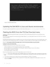
...update flash process from the F12 menu: CAUTION: Do not power off state, insert the USB key where you can run the BIOS update file from the Dell Support website and copied to the root of the USB key • AC power adapter connected to the system • Functional system battery to flash... the BIOS Perform the following steps to see https://www.dell.com/support/article/sln171755/.
...update flash process from the F12 menu: CAUTION: Do not power off state, insert the USB key where you can run the BIOS update file from the Dell Support website and copied to the root of the USB key • AC power adapter connected to the system • Functional system battery to flash... the BIOS Perform the following steps to see https://www.dell.com/support/article/sln171755/.
Ownerss Manual
Page 75
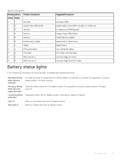
chipset 2 7 display 3 1 RTC power failure 3 2 PCI/Video 3 3 BIOS recovery 1 3 4 BIOS recovery 2 Battery status lights Suggested Resolution processor failure system board, covers BIOS corruption or ROM error no memory/no ... battery connector, replace battery if the issue reoccurs. Fatal battery failure with AC adapter present. Battery in charge mode with steady white light Constantly blinking amber light Light off White light on An unauthenticated or unsupported non-Dell AC adapter is attached to an electrical outlet, the battery light operates as follows: Alternately...
chipset 2 7 display 3 1 RTC power failure 3 2 PCI/Video 3 3 BIOS recovery 1 3 4 BIOS recovery 2 Battery status lights Suggested Resolution processor failure system board, covers BIOS corruption or ROM error no memory/no ... battery connector, replace battery if the issue reoccurs. Fatal battery failure with AC adapter present. Battery in charge mode with steady white light Constantly blinking amber light Light off White light on An unauthenticated or unsupported non-Dell AC adapter is attached to an electrical outlet, the battery light operates as follows: Alternately...


