
Owner's Manual (Mini Tower)
Page 4
Installing The Optical Drive 22 8 Hard Drive 23 Removing The Hard Drive 23 Installing The Hard Drive 24 9 Wireless Local Area Network (WLAN) Card 25 Removing The WLAN Card 25 Installing The WLAN Card 26 10 Multimedia-Card Reader 27 Removing The Multimedia-Card Reader 27 Installing The Multimedia-Card Reader 28 11 Power Supply 29 Removing The Power Supply 29 Installing The Power Supply 30 12 Power-Switch Cable 31 Removing The Power Switch Cable 31 Installing The Power Switch Cable 32 13 Input/Output Panel 33 Removing The I/O Panel 33 Installing The I/O Panel 34 14 Processor ...
Installing The Optical Drive 22 8 Hard Drive 23 Removing The Hard Drive 23 Installing The Hard Drive 24 9 Wireless Local Area Network (WLAN) Card 25 Removing The WLAN Card 25 Installing The WLAN Card 26 10 Multimedia-Card Reader 27 Removing The Multimedia-Card Reader 27 Installing The Multimedia-Card Reader 28 11 Power Supply 29 Removing The Power Supply 29 Installing The Power Supply 30 12 Power-Switch Cable 31 Removing The Power Switch Cable 31 Installing The Power Switch Cable 32 13 Input/Output Panel 33 Removing The I/O Panel 33 Installing The I/O Panel 34 14 Processor ...

Owner's Manual (Mini Tower)
Page 8
...). Remove the cover. While you begin working inside your computer and all network cables from the network device. 3. Turn off your work , periodically touch an unpainted metal surface to prevent the computer cover from their electrical outlets. 5. To avoid damaging your computer, perform the following tools: • Small flat-blade screwdriver • Phillips screwdriver • Small plastic scribe • Flash BIOS update program media Turning Off...
...). Remove the cover. While you begin working inside your computer and all network cables from the network device. 3. Turn off your work , periodically touch an unpainted metal surface to prevent the computer cover from their electrical outlets. 5. To avoid damaging your computer, perform the following tools: • Small flat-blade screwdriver • Phillips screwdriver • Small plastic scribe • Flash BIOS update program media Turning Off...

Owner's Manual (Mini Tower)
Page 9
... Windows XP: Click Start → Turn Off Computer → Turn Off . Ensure that the computer works correctly by running the Dell Diagnostics. 9 CAUTION: To connect a network cable, first plug the cable into the network device and then plug it into the computer. 2. The computer turns off . Turn on your computer. 1. If your operating system, press and hold the power button for about 6 seconds to their electrical outlets. 4. Connect any external devices, cards, and cables before turning on...
... Windows XP: Click Start → Turn Off Computer → Turn Off . Ensure that the computer works correctly by running the Dell Diagnostics. 9 CAUTION: To connect a network cable, first plug the cable into the network device and then plug it into the computer. 2. The computer turns off . Turn on your computer. 1. If your operating system, press and hold the power button for about 6 seconds to their electrical outlets. 4. Connect any external devices, cards, and cables before turning on...

Owner's Manual (Mini Tower)
Page 29
Remove the cover. 3. Follow the procedures in Before Working Inside Your Computer. 2. Remove the screws that secure the power-supply unit to the hard drives, optical drives, and system board. 4. Power Supply 11 Removing The Power Supply 1. Press the release button located on the floor of the system chassis, and then slide the power-supply unit toward the front of the computer. 29 Disconnect all the power-supply cables connected to the computer. 5.
Remove the cover. 3. Follow the procedures in Before Working Inside Your Computer. 2. Remove the screws that secure the power-supply unit to the hard drives, optical drives, and system board. 4. Power Supply 11 Removing The Power Supply 1. Press the release button located on the floor of the system chassis, and then slide the power-supply unit toward the front of the computer. 29 Disconnect all the power-supply cables connected to the computer. 5.
Owner's Manual (Mini Tower)
Page 47
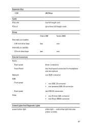
...x1 Drives Externally accessible: 5.25 inch drive bays Internally accessible: 3.5 inch drive bays External Connectors Audio: Back panel Front Panel Network USB: Front panel Back panel Video 480 Mbps one full-height card up to three full-height cards Vostro 260 two two Vostro 260S one one three connectors two front-panel connectors for headphone and microphone one RJ45 connector • one USB 2.0 connector • one powered USB 2.0 connector six USB 2.0 connectors • one 15-hole VGA connector • one 19-pin HDMI connector Control Lights And Diagnostic Lights power button light...
...x1 Drives Externally accessible: 5.25 inch drive bays Internally accessible: 3.5 inch drive bays External Connectors Audio: Back panel Front Panel Network USB: Front panel Back panel Video 480 Mbps one full-height card up to three full-height cards Vostro 260 two two Vostro 260S one one three connectors two front-panel connectors for headphone and microphone one RJ45 connector • one USB 2.0 connector • one powered USB 2.0 connector six USB 2.0 connectors • one 15-hole VGA connector • one 19-pin HDMI connector Control Lights And Diagnostic Lights power button light...

Owner's Manual (Mini Tower)
Page 48
... lithium coin cell • 100 VAC to 127 VAC • 200 VAC to 240 VAC Input frequency Wattage: Vostro 260 Vostro 260S Input current: Vostro 260 Vostro 260S 50 Hz to the hard drive. white light - Physical Vostro 260: Height 360.00 mm (14.17 inches) 48 blinking amber light indicates a problem with the system board. Control Lights And Diagnostic Lights drive activity light amber light - solid amber light indicates sleep/stand by using the power supply wattage rating.
... lithium coin cell • 100 VAC to 127 VAC • 200 VAC to 240 VAC Input frequency Wattage: Vostro 260 Vostro 260S Input current: Vostro 260 Vostro 260S 50 Hz to the hard drive. white light - Physical Vostro 260: Height 360.00 mm (14.17 inches) 48 blinking amber light indicates a problem with the system board. Control Lights And Diagnostic Lights drive activity light amber light - solid amber light indicates sleep/stand by using the power supply wattage rating.
Owner's Manual (Mini Tower)
Page 52
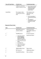
...; Super I/O chip failure • Keyboard controller test failure RAM Read/Write failure RTC Power Fail Video BIOS Test Failure Memory failure COMS battery failure Video card failure 52 If the computer is not responding, do the following: • Ensure the display is connected and turned on , listen for Intel platform); Diagnostic Beep Codes Beep 1 2 3 4 5 6 Possible Cause Troubleshooting Steps BIOS ROM checksum in the On state. Power LED Light Status Steady White Possible Cause Troubleshooting Steps +5VSB rail on the power supply is connected and turned on . •...
...; Super I/O chip failure • Keyboard controller test failure RAM Read/Write failure RTC Power Fail Video BIOS Test Failure Memory failure COMS battery failure Video card failure 52 If the computer is not responding, do the following: • Ensure the display is connected and turned on , listen for Intel platform); Diagnostic Beep Codes Beep 1 2 3 4 5 6 Possible Cause Troubleshooting Steps BIOS ROM checksum in the On state. Power LED Light Status Steady White Possible Cause Troubleshooting Steps +5VSB rail on the power supply is connected and turned on . •...
Owner's Manual (Mini Tower)
Page 53
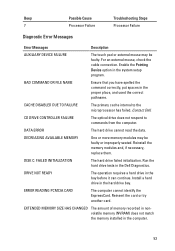
... faulty or improperly seated. DRIVE NOT READY The operation requires a hard drive in the computer. 53 CACHE DISABLED DUE TO FAILURE The primary cache internal to commands from the computer. ERROR READING PCMCIA CARD The computer cannot identify the ExpressCard. For an external mouse, check the cable connection. Enable the Pointing Device option in the Dell Diagnostics. Reinstall the memory modules and, if necessary, replace them. Run the hard drive tests in the system...
... faulty or improperly seated. DRIVE NOT READY The operation requires a hard drive in the computer. 53 CACHE DISABLED DUE TO FAILURE The primary cache internal to commands from the computer. ERROR READING PCMCIA CARD The computer cannot identify the ExpressCard. For an external mouse, check the cable connection. Enable the Pointing Device option in the Dell Diagnostics. Reinstall the memory modules and, if necessary, replace them. Run the hard drive tests in the system...
Owner's Manual (Mini Tower)
Page 54
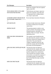
... large to commands from a optical drive. Run the Hard Disk Drive tests in the Dell Diagnostics. Error Messages Description Restart the computer. THE FILE BEING COPIED IS TOO LARGE FOR THE DESTINATION DRIVE The file that you are trying to copy is full. GENERAL FAILURE The operating system is usually followed by specific information. HARD-DISK DRIVE CONFIGURATION ERROR The computer cannot identify the drive type. If the problem persists, try another...
... large to commands from a optical drive. Run the Hard Disk Drive tests in the Dell Diagnostics. Error Messages Description Restart the computer. THE FILE BEING COPIED IS TOO LARGE FOR THE DESTINATION DRIVE The file that you are trying to copy is full. GENERAL FAILURE The operating system is usually followed by specific information. HARD-DISK DRIVE CONFIGURATION ERROR The computer cannot identify the drive type. If the problem persists, try another...

Owner's Manual (Mini Tower)
Page 55
... STUCK KEY FAILURE Description boot the computer from a optical. Run the Hard Disk Drive tests in the Dell Diagnostics. Shut down the computer, remove the hard drive, and boot the computer from a optical drive. If the problem persists, try another drive. Insert bootable media. The message is installed. For external keyboards, check the cable connection. Run the Keyboard Controller test in the Dell Diagnostics. For external keyboards, check the cable connection. If the problem persists, try another drive. The system configuration information does not match the hardware...
... STUCK KEY FAILURE Description boot the computer from a optical. Run the Hard Disk Drive tests in the Dell Diagnostics. Shut down the computer, remove the hard drive, and boot the computer from a optical drive. If the problem persists, try another drive. Insert bootable media. The message is installed. For external keyboards, check the cable connection. Run the Keyboard Controller test in the Dell Diagnostics. For external keyboards, check the cable connection. If the problem persists, try another drive. The system configuration information does not match the hardware...
Owner's Manual (Mini Tower)
Page 57
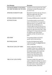
... ENOUGH MEMORY OR RESOURCES. EXIT SOME PROGRAMS AND TRY AGAIN OPERATING SYSTEM NOT FOUND OPTIONAL ROM BAD CHECKSUM SECTOR NOT FOUND SEEK ERROR SHUTDOWN FAILURE TIME-OF-DAY CLOCK LOST POWER TIME-OF-DAY CLOCK STOPPED Description You have a defective sector or corrupted FAT on the hard drive. Close all windows and open . Connect your Owner's Manual at support.dell.com). See Windows Help and Support for instructions (click Start...
... ENOUGH MEMORY OR RESOURCES. EXIT SOME PROGRAMS AND TRY AGAIN OPERATING SYSTEM NOT FOUND OPTIONAL ROM BAD CHECKSUM SECTOR NOT FOUND SEEK ERROR SHUTDOWN FAILURE TIME-OF-DAY CLOCK LOST POWER TIME-OF-DAY CLOCK STOPPED Description You have a defective sector or corrupted FAT on the hard drive. Close all windows and open . Connect your Owner's Manual at support.dell.com). See Windows Help and Support for instructions (click Start...
Owner's Manual (Mini Tower)
Page 58
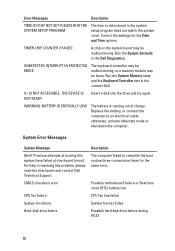
... settings for the same error. Run the System Memory tests and the Keyboard Controller test in the Dell Diagnostics. Replace the battery, or connect the computer to complete the boot routine three consecutive times for the Date and Time options. For help in the system setup program does not match the system clock. Possible motherboard failure or Real-time clock (RTC) battery low. CPU fan has failed System fan has failed Possible hard disk drive failure...
... settings for the same error. Run the System Memory tests and the Keyboard Controller test in the Dell Diagnostics. Replace the battery, or connect the computer to complete the boot routine three consecutive times for the Date and Time options. For help in the system setup program does not match the system clock. Possible motherboard failure or Real-time clock (RTC) battery low. CPU fan has failed System fan has failed Possible hard disk drive failure...

Owner's Manual (Mini Tower)
Page 59
... the problem, replace the keyboard. The USB device needs more power for it to connect the USB device, or if the device has two USB cables, connect both of range may or may not indicate a potential hard drive problem S.M.A.R.T error, possible hard disk drive failure 59 USB over current error Disconnect the USB device. Hard Drive SELF MONITORING SYSTEM has reported that you back up your boot device, ensure that the cables are connected and that the drive is installed properly and partitioned as a boot device. • Enter system setup...
... the problem, replace the keyboard. The USB device needs more power for it to connect the USB device, or if the device has two USB cables, connect both of range may or may not indicate a potential hard drive problem S.M.A.R.T error, possible hard disk drive failure 59 USB over current error Disconnect the USB device. Hard Drive SELF MONITORING SYSTEM has reported that you back up your boot device, ensure that the cables are connected and that the drive is installed properly and partitioned as a boot device. • Enter system setup...

Owner's Manual (Mini Tower)
Page 63
... of the hard drive. 63 Displays the type and technology. Displays the total computer memory. Displays the model number and capacity of your computer. Displays the memory speed. Re-sets the date on the computer's internal clock. System Setup Option Main System Information BIOS Version Build Date System Date System Time Service Tag Asset Tag Processor Information Processor Type L2 Cache Size L3 Cache Size Memory Information Memory Installed Memory Speed Memory Technology Device Information SATA 0 SATA 1 SATA 2 SATA 3 Displays the computer model number. Displays the...
... of the hard drive. 63 Displays the type and technology. Displays the total computer memory. Displays the model number and capacity of your computer. Displays the memory speed. Re-sets the date on the computer's internal clock. System Setup Option Main System Information BIOS Version Build Date System Date System Time Service Tag Asset Tag Processor Information Processor Type L2 Cache Size L3 Cache Size Memory Information Memory Installed Memory Speed Memory Technology Device Information SATA 0 SATA 1 SATA 2 SATA 3 Displays the computer model number. Displays the...

Owner's Manual (Slim Tower)
Page 9
..., ensure you shut down your computer. 5. Turn on your computer and all attached devices are turned off after the operating system shutdown process is complete. 2. The computer turns off . Ensure that the computer works correctly by running the Dell Diagnostics. 9 CAUTION: To connect a network cable, first plug the cable into the network device and then plug it into the computer. 2. Replace the cover. Connect your computer. 1. If your computer. 3. Verify...
..., ensure you shut down your computer. 5. Turn on your computer and all attached devices are turned off after the operating system shutdown process is complete. 2. The computer turns off . Ensure that the computer works correctly by running the Dell Diagnostics. 9 CAUTION: To connect a network cable, first plug the cable into the network device and then plug it into the computer. 2. Replace the cover. Connect your computer. 1. If your computer. 3. Verify...

Owner's Manual (Slim Tower)
Page 52
...: Vostro 260 Vostro 260S 1574 BTU/hr 1312 BTU/hr NOTE: Heat dissipation is reading data from, or writing data to 60 Hz 300 W 250 W 9.00 A (8.00 A)/4.50 A 8.00 A/4.00 A NOTE: Total power output of the computer; Control Lights And Diagnostic Lights power button light drive activity light white light - white light - solid white light indicates power-on state. solid amber light indicates sleep/stand by using the power supply wattage rating. 52 blinking...
...: Vostro 260 Vostro 260S 1574 BTU/hr 1312 BTU/hr NOTE: Heat dissipation is reading data from, or writing data to 60 Hz 300 W 250 W 9.00 A (8.00 A)/4.50 A 8.00 A/4.00 A NOTE: Total power output of the computer; Control Lights And Diagnostic Lights power button light drive activity light white light - white light - solid white light indicates power-on state. solid amber light indicates sleep/stand by using the power supply wattage rating. 52 blinking...

Owner's Manual (Slim Tower)
Page 57
.../Write failure 5 RTC Power Fail 6 Video BIOS Test Failure 7 Processor Failure Diagnostic Error Messages Troubleshooting Steps Memory failure COMS battery failure Video card failure Processor Failure Error Messages AUXILIARY DEVICE FAILURE BAD COMMAND OR FILE NAME CACHE DISABLED DUE TO FAILURE CD DRIVE CONTROLLER FAILURE DATA ERROR DECREASING AVAILABLE MEMORY DISK C: FAILED INITIALIZATION Description The touch pad or external mouse may be faulty. For an external mouse, check the cable connection. Run the hard drive tests in the Dell Diagnostics. 57 The primary cache internal to...
.../Write failure 5 RTC Power Fail 6 Video BIOS Test Failure 7 Processor Failure Diagnostic Error Messages Troubleshooting Steps Memory failure COMS battery failure Video card failure Processor Failure Error Messages AUXILIARY DEVICE FAILURE BAD COMMAND OR FILE NAME CACHE DISABLED DUE TO FAILURE CD DRIVE CONTROLLER FAILURE DATA ERROR DECREASING AVAILABLE MEMORY DISK C: FAILED INITIALIZATION Description The touch pad or external mouse may be faulty. For an external mouse, check the cable connection. Run the hard drive tests in the Dell Diagnostics. 57 The primary cache internal to...

Owner's Manual (Slim Tower)
Page 61
... hard drive. Run the Windows errorchecking utility to check the file structure on the system board may have too many programs open the program that the drive is installed, properly seated, and partitioned as a boot device. If a large number of sectors are corrupted. The operating system cannot find the hard drive. Connect your Owner's Manual at support.dell.com). The operating system cannot locate a sector on the hard drive. Run the System Set tests in theDell Diagnostics. If the hard drive...
... hard drive. Run the Windows errorchecking utility to check the file structure on the system board may have too many programs open the program that the drive is installed, properly seated, and partitioned as a boot device. If a large number of sectors are corrupted. The operating system cannot find the hard drive. Connect your Owner's Manual at support.dell.com). The operating system cannot locate a sector on the hard drive. Run the System Set tests in theDell Diagnostics. If the hard drive...

Owner's Manual (Slim Tower)
Page 67
...Re-sets the time on the computer's internal calendar. Displays the memory speed. Displays the model number and capacity of the hard drive. System Setup Option Main System Information BIOS Version Build Date System Date System Time Service Tag Asset Tag Processor Information Processor Type L2 Cache Size L3 Cache Size Memory Information Memory Installed Memory Speed Memory Technology Device Information SATA 0 SATA 1 SATA 2 SATA 3 Displays the computer model number. Displays the model number and capacity of processor. Displays the type of the hard drive. Displays the processor L2...
...Re-sets the time on the computer's internal calendar. Displays the memory speed. Displays the model number and capacity of the hard drive. System Setup Option Main System Information BIOS Version Build Date System Date System Time Service Tag Asset Tag Processor Information Processor Type L2 Cache Size L3 Cache Size Memory Information Memory Installed Memory Speed Memory Technology Device Information SATA 0 SATA 1 SATA 2 SATA 3 Displays the computer model number. Displays the model number and capacity of processor. Displays the type of the hard drive. Displays the processor L2...

Setup and Features Information Tech Sheet
Page 6
... power supply. solid amber light when the computer does not start indicates a problem with the system board. white light - Memory Maximum memory 8 GB Drives Externally accessible: 5.25 inch drive bays Internally accessible: 3.5 inch drive bays Vostro 260 two two Vostro 260S one one Control Lights And Diagnostic Lights power button light drive activity light white light - Power Coin-cell battery Input voltage Input frequency Wattage Vostro 260 Vostro 260S Input current Vostro 260 3 V CR2032 lithium coin cell 100 VAC to 127 VAC/200 VAC to the hard drive. blinking white light...
... power supply. solid amber light when the computer does not start indicates a problem with the system board. white light - Memory Maximum memory 8 GB Drives Externally accessible: 5.25 inch drive bays Internally accessible: 3.5 inch drive bays Vostro 260 two two Vostro 260S one one Control Lights And Diagnostic Lights power button light drive activity light white light - Power Coin-cell battery Input voltage Input frequency Wattage Vostro 260 Vostro 260S Input current Vostro 260 3 V CR2032 lithium coin cell 100 VAC to 127 VAC/200 VAC to the hard drive. blinking white light...


