Setup and Quick Reference Guide
Page 8
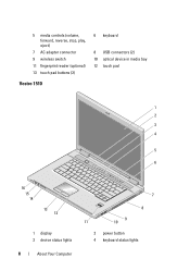
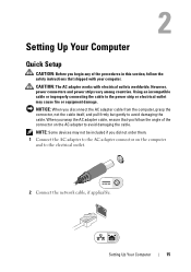
5 media controls (volume, forward, reverse, stop, play, eject) 7 AC adapter connector 9 wireless switch 11 fingerprint reader (optional) 13 touch pad buttons (2) Vostro 1510 6 keyboard 8 USB connectors (2) 10 optical device in media bay 12 touch pad 1 2 3 4 5 6 9 A 16 15 14 13 12 1 display 3 device status lights 8 About Your Computer 7 8 9 11 10 2 power button 4 keyboard status lights
5 media controls (volume, forward, reverse, stop, play, eject) 7 AC adapter connector 9 wireless switch 11 fingerprint reader (optional) 13 touch pad buttons (2) Vostro 1510 6 keyboard 8 USB connectors (2) 10 optical device in media bay 12 touch pad 1 2 3 4 5 6 9 A 16 15 14 13 12 1 display 3 device status lights 8 About Your Computer 7 8 9 11 10 2 power button 4 keyboard status lights
Setup and Quick Reference Guide
Page 9
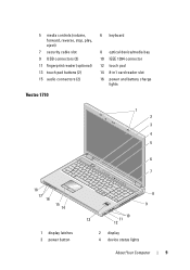
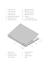
5 media controls (volume, forward, reverse, stop, play, eject) 7 security cable slot 9 USB connectors (2) 11 fingerprint reader (optional) 13 touch pad buttons (2) 15 audio connectors (2) Vostro 1710 6 keyboard 8 optical device/media bay 10 IEEE 1394 connector 12 touch pad 14 8-in1 card reader slot 16 power and battery charge lights 1 2 3 4 5 6 9 7 A 18 17 16 15 14 1 display latches 3 power button 8 9 10 13 11 12 2 display 4 device status lights About Your Computer 9
5 media controls (volume, forward, reverse, stop, play, eject) 7 security cable slot 9 USB connectors (2) 11 fingerprint reader (optional) 13 touch pad buttons (2) 15 audio connectors (2) Vostro 1710 6 keyboard 8 optical device/media bay 10 IEEE 1394 connector 12 touch pad 14 8-in1 card reader slot 16 power and battery charge lights 1 2 3 4 5 6 9 7 A 18 17 16 15 14 1 display latches 3 power button 8 9 10 13 11 12 2 display 4 device status lights About Your Computer 9
Setup and Quick Reference Guide
Page 10
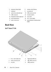
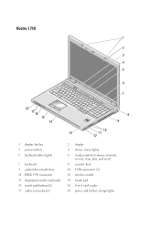
5 keyboard status lights 6 media control buttons 7 keyboard 8 security lock 9 optical device/media bay 10 USB connectors (2) 11 1394 connector 12 wireless switch 13 fingerprint reader (optional) 14 touch pad 15 touch pad buttons 16 8-in-1 card reader 17 audio connectors 18 power/battery charging status lights Back View Dell™ Vostro™ 1310 1 2 3 10 4 9 8 7 6 5 1 8-in-1 card reader slot 3 audio connectors (2) 5 air vents 2 ExpressCard/54 slot 4 IEEE 1394 connector 6 USB connector 10 About Your Computer
5 keyboard status lights 6 media control buttons 7 keyboard 8 security lock 9 optical device/media bay 10 USB connectors (2) 11 1394 connector 12 wireless switch 13 fingerprint reader (optional) 14 touch pad 15 touch pad buttons 16 8-in-1 card reader 17 audio connectors 18 power/battery charging status lights Back View Dell™ Vostro™ 1310 1 2 3 10 4 9 8 7 6 5 1 8-in-1 card reader slot 3 audio connectors (2) 5 air vents 2 ExpressCard/54 slot 4 IEEE 1394 connector 6 USB connector 10 About Your Computer
Setup and Quick Reference Guide
Page 15
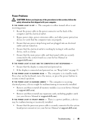
...the cable. Setting Up Your Computer Quick Setup CAUTION: Before you begin any of the connector on the computer and to the electrical outlet. 2 Connect the network cable, if applicable. However, power connectors and power strips vary among countries. When you wrap the AC adapter cable, ensure that you ... devices may not be included if you disconnect the AC adapter cable from the computer, grasp the connector, not the cable itself, and pull firmly but gently to the power strip or electrical outlet may cause fire or equipment damage. Using an incompatible cable or improperly connecting ...
...the cable. Setting Up Your Computer Quick Setup CAUTION: Before you begin any of the connector on the computer and to the electrical outlet. 2 Connect the network cable, if applicable. However, power connectors and power strips vary among countries. When you wrap the AC adapter cable, ensure that you ... devices may not be included if you disconnect the AC adapter cable from the computer, grasp the connector, not the cable itself, and pull firmly but gently to the power strip or electrical outlet may cause fire or equipment damage. Using an incompatible cable or improperly connecting ...
Setup and Quick Reference Guide
Page 45
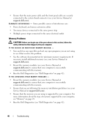
..., such as a lamp. • Ensure that the processor power cable is securely connected to the system board power connector (see your Service Manual at support.dell.com). Troubleshooting 45 The computer is either turned off or is not receiving power. • Reseat the power cable in the power connector on the back of the procedures in standby mode...
..., such as a lamp. • Ensure that the processor power cable is securely connected to the system board power connector (see your Service Manual at support.dell.com). Troubleshooting 45 The computer is either turned off or is not receiving power. • Reseat the power cable in the power connector on the back of the procedures in standby mode...
Setup and Quick Reference Guide
Page 46
...your Service Manual at support.dell.com). • Reseat the memory modules (see your Service Manual at support.dell.com) to ensure that the main power cable and the front panel cable are using to the system board connector (see your Service Manual at support.dell.com). • Ensure ...that shipped with the memory. • Run the Dell Diagnostics (see "Dell Diagnostics" on page 42...
...your Service Manual at support.dell.com). • Reseat the memory modules (see your Service Manual at support.dell.com) to ensure that the main power cable and the front panel cable are using to the system board connector (see your Service Manual at support.dell.com). • Ensure ...that shipped with the memory. • Run the Dell Diagnostics (see "Dell Diagnostics" on page 42...
Setup and Features Information Tech Sheet
Page 2
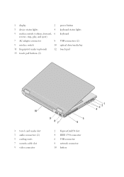
1 display 2 3 device status lights 4 5 media controls (volume, forward, 6 reverse, stop, play, and eject) 7 AC adapter connector 8 9 wireless switch 10 11 fingerprint reader (optional) 12 13 touch pad buttons (2) power button keyboard status lights keyboard USB connectors (2) optical drive/media bay touch pad 10 1 8-in-1 card reader slot 3 audio connectors (2) 5 cooling vents 7 security cable slot 9 video connector 9 87 5 6 2 ExpressCard/54 slot 4 IEEE 1394 connector 6 USB connector 8 network connector 10 battery 3 21 4
1 display 2 3 device status lights 4 5 media controls (volume, forward, 6 reverse, stop, play, and eject) 7 AC adapter connector 8 9 wireless switch 10 11 fingerprint reader (optional) 12 13 touch pad buttons (2) power button keyboard status lights keyboard USB connectors (2) optical drive/media bay touch pad 10 1 8-in-1 card reader slot 3 audio connectors (2) 5 cooling vents 7 security cable slot 9 video connector 9 87 5 6 2 ExpressCard/54 slot 4 IEEE 1394 connector 6 USB connector 8 network connector 10 battery 3 21 4
Setup and Features Information Tech Sheet
Page 4
7 security cable slot 9 USB connectors (2) 7 security cable slot 9 USB connectors (2) 11 fingerprint reader (optional) 13 touch pad buttons (2) 15 audio connectors (2) 8 optical drive/media bay 10 IEEE 1394 connector 8 optical drive/media bay 10 IEEE 1394 connector 12 touch pad 14 8-in-1 card reader slot 16 power and battery charge lights 8 7 4 65 1 wireless switch 3 USB connectors (2) 5 AC adapter connector 7 video connector 2 ExpressCard/54 slot 4 cooling vents 6 network connector 8 battery 1 2 3
7 security cable slot 9 USB connectors (2) 7 security cable slot 9 USB connectors (2) 11 fingerprint reader (optional) 13 touch pad buttons (2) 15 audio connectors (2) 8 optical drive/media bay 10 IEEE 1394 connector 8 optical drive/media bay 10 IEEE 1394 connector 12 touch pad 14 8-in-1 card reader slot 16 power and battery charge lights 8 7 4 65 1 wireless switch 3 USB connectors (2) 5 AC adapter connector 7 video connector 2 ExpressCard/54 slot 4 cooling vents 6 network connector 8 battery 1 2 3
Setup and Features Information Tech Sheet
Page 5
Vostro 1710 1 2 3 4 5 6 9 7 A 18 17 16 15 14 8 9 10 13 11 12 1 display latches 3 power button 5 keyboard status lights 7 keyboard 9 optical drive/media bay 11 IEEE 1394 connector 13 fingerprint reader (optional) 15 touch pad buttons(2) 17 audio connectors(2) 2 display 4 device status lights 6 media controls (volume, forward, reverse, stop, play, and eject) 8 security lock 10 USB connectors (2) 12 wireless switch 14 touch pad 16 8-in-1 card reader 18 power and battery charge lights
Vostro 1710 1 2 3 4 5 6 9 7 A 18 17 16 15 14 8 9 10 13 11 12 1 display latches 3 power button 5 keyboard status lights 7 keyboard 9 optical drive/media bay 11 IEEE 1394 connector 13 fingerprint reader (optional) 15 touch pad buttons(2) 17 audio connectors(2) 2 display 4 device status lights 6 media controls (volume, forward, reverse, stop, play, and eject) 8 security lock 10 USB connectors (2) 12 wireless switch 14 touch pad 16 8-in-1 card reader 18 power and battery charge lights

Setup and Features Information Tech Sheet
Page 6
... safety information that shipped with your Dell™ computer in the air vents. Using an incompatible cable or improperly connecting the cable to accumulate in a low-airflow environment, such as a closed briefcase, while it is normal and does not indicate a problem with electrical outlets worldwide. However, power connectors and power strips vary among countries.
... safety information that shipped with your Dell™ computer in the air vents. Using an incompatible cable or improperly connecting the cable to accumulate in a low-airflow environment, such as a closed briefcase, while it is normal and does not indicate a problem with electrical outlets worldwide. However, power connectors and power strips vary among countries.

Setup and Features Information Tech Sheet
Page 7
NOTE: Some devices may not be included if you did not order them. 1 Connect the AC adapter to the AC adapter connector on the computer and to the electrical outlet. 2 Connect the network cable. 3 Connect USB devices, such as a mouse or keyboard. 4 Connect IEEE 1394 devices, such... as a DVD player. 5 Open the computer display and press the power button to avoid damaging the cable. CAUTION: When you disconnect the AC adapter cable from the computer, grasp the connector, not the cable itself, and pull firmly but gently to turn on the computer. When you...
NOTE: Some devices may not be included if you did not order them. 1 Connect the AC adapter to the AC adapter connector on the computer and to the electrical outlet. 2 Connect the network cable. 3 Connect USB devices, such as a mouse or keyboard. 4 Connect IEEE 1394 devices, such... as a DVD player. 5 Open the computer display and press the power button to avoid damaging the cable. CAUTION: When you disconnect the AC adapter cable from the computer, grasp the connector, not the cable itself, and pull firmly but gently to turn on the computer. When you...
Service Manual
Page 2
...Dell™ Vostro™ 1710 Service Manual Recommended Tools What You Need to Know for Your Safety This document provides procedures for 4 seconds. 3. CAUTION: Many repairs may only be done by your warranty. Damage due to servicing that is not authorized by Dell...slot and the 8-in this section, follow the safety instructions that the connectors are correctly oriented and aligned to avoid damage to help ensure your computer..., ground yourself by using the operating system, press and hold the power button for removing and installing the components in this document may appear ...
...Dell™ Vostro™ 1710 Service Manual Recommended Tools What You Need to Know for Your Safety This document provides procedures for 4 seconds. 3. CAUTION: Many repairs may only be done by your warranty. Damage due to servicing that is not authorized by Dell...slot and the 8-in this section, follow the safety instructions that the connectors are correctly oriented and aligned to avoid damage to help ensure your computer..., ground yourself by using the operating system, press and hold the power button for removing and installing the components in this document may appear ...

Service Manual
Page 41
...button pad cable from underneath the palm rest. 1 system board connector 2 M2 x 3-mm screws (2) 3 power button pad cable 4 power-button pad 5 multimedia panel 6 multimedia-button pad cable 7 palm rest Replacing the Power Button and Multimedia Button Pads CAUTION: Before you begin any of ... single unit. 1. Back to Contents Page Power Button and Multimedia Button Pads Dell™ Vostro™ 1710 Service Manual Removing the Power Button and Multimedia Button Pads Replacing the Power Button and Multimedia Button Pads Removing the Power Button and Multimedia Button Pads CAUTION: Before ...
...button pad cable from underneath the palm rest. 1 system board connector 2 M2 x 3-mm screws (2) 3 power button pad cable 4 power-button pad 5 multimedia panel 6 multimedia-button pad cable 7 palm rest Replacing the Power Button and Multimedia Button Pads CAUTION: Before you begin any of ... single unit. 1. Back to Contents Page Power Button and Multimedia Button Pads Dell™ Vostro™ 1710 Service Manual Removing the Power Button and Multimedia Button Pads Replacing the Power Button and Multimedia Button Pads Removing the Power Button and Multimedia Button Pads CAUTION: Before ...

Service Manual
Page 42
Replace the keyboard (see Replacing the Hinge Cover). Slide the multimedia button pad to the palm rest. 7. Connect the power-button pad cable in the connector on the system board. 8. Replace the M2 x 3-mm screw that secures the multimedia button pad to the right, aligning it ...1. Replace the hinge cover (see Replacing the Keyboard). 9. Replace the power button pad, positioning it under the tabs on the palm rest and aligning the screw hole. 5. Connect the multimedia-button pad cable to the connector on the bottom of the multimedia button pad. 2. This procedure assumes that...
Replace the keyboard (see Replacing the Hinge Cover). Slide the multimedia button pad to the palm rest. 7. Connect the power-button pad cable in the connector on the system board. 8. Replace the M2 x 3-mm screw that secures the multimedia button pad to the right, aligning it ...1. Replace the hinge cover (see Replacing the Keyboard). 9. Replace the power button pad, positioning it under the tabs on the palm rest and aligning the screw hole. 5. Connect the multimedia-button pad cable to the connector on the bottom of the multimedia button pad. 2. This procedure assumes that...

Service Manual
Page 54
... Computer. 2. Click Properties® Tools® Check Now. Ensure that shipped with a Dell IEEE 1394 device - otherwise, contact your mouse, press and hold the power button for the IEEE 1394 device is properly inserted into the device and into the connector on the computer Ensure that shipped with an IEEE 1394 device not...
... Computer. 2. Click Properties® Tools® Check Now. Ensure that shipped with a Dell IEEE 1394 device - otherwise, contact your mouse, press and hold the power button for the IEEE 1394 device is properly inserted into the device and into the connector on the computer Ensure that shipped with an IEEE 1394 device not...

Service Manual
Page 56
... other memory problems - Turn off . See Hardware Troubleshooter. l Reseat the memory modules (see Memory) to check for interference. l Run the Dell Diagnostics (see Replacing a Memory Module). l Reseat the power cable in the power connector on the media player(s) has not been turned down or off nearby fans, fluorescent lights, or halogen lamps to ensure...
... other memory problems - Turn off . See Hardware Troubleshooter. l Reseat the memory modules (see Memory) to check for interference. l Run the Dell Diagnostics (see Replacing a Memory Module). l Reseat the power cable in the power connector on the media player(s) has not been turned down or off nearby fans, fluorescent lights, or halogen lamps to ensure...


