Owners Manual
Page 3
... Drive...13 Installing the Hard Drive...14 Removing the Memory Module...14 Installing the Memory Module...14 Removing the WLAN Card...15 Installing the WLAN Card...15 Removing the Keyboard...15 Installing the Keyboard...16 Removing the Palmrest Assembly...18 Installing the Palmrest Assembly...19 Removing the Battery Connector...20 Installing the Battery Connector...20...
... Drive...13 Installing the Hard Drive...14 Removing the Memory Module...14 Installing the Memory Module...14 Removing the WLAN Card...15 Installing the WLAN Card...15 Removing the Keyboard...15 Installing the Keyboard...16 Removing the Palmrest Assembly...18 Installing the Palmrest Assembly...19 Removing the Battery Connector...20 Installing the Battery Connector...20...
Owners Manual
Page 15
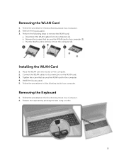
.... 5. Follow the procedures in After Working Inside Your computer. Perform the following steps to the computer [2]. c. Release the keyboard by pressing the tabs using a scribe. 15 Remove the screws that secures the WLAN card to its slot on the WLAN card. 3. Tighten the screw that secures the... WLAN card to remove the WLAN card: a. Place the WLAN card into its connectors on the computer. 2. Removing the Keyboard 1. Installing the ...
.... 5. Follow the procedures in After Working Inside Your computer. Perform the following steps to the computer [2]. c. Release the keyboard by pressing the tabs using a scribe. 15 Remove the screws that secures the WLAN card to its slot on the WLAN card. 3. Tighten the screw that secures the... WLAN card to remove the WLAN card: a. Place the WLAN card into its connectors on the computer. 2. Removing the Keyboard 1. Installing the ...
Owners Manual
Page 16
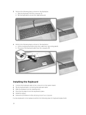
... disconnect the cable from the computer [2]. Connect the keyboard cable to access the cable below [2]. 4. b. Slide the keyboard into the retaining slots. 4. If a new keyboard is to lock the keyboard in the illustration: a. Flip the keyboard to the connector on the system board. 2. Flip the keyboard after connecting the keyboard cable. 3. Follow the procedures in the illustration...
... disconnect the cable from the computer [2]. Connect the keyboard cable to access the cable below [2]. 4. b. Slide the keyboard into the retaining slots. 4. If a new keyboard is to lock the keyboard in the illustration: a. Flip the keyboard to the connector on the system board. 2. Flip the keyboard after connecting the keyboard cable. 3. Follow the procedures in the illustration...
Owners Manual
Page 17
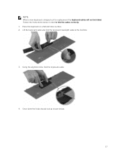
Lift the keyboard cable and fold the keyboard-backlight cable at the fold line. 3. Place the keyboard on a flat and clean surface. 2. Once done the folds should look as shown below in order to fold the cables correctly: 1. Follow the instructions below . 17 Using the alignment line, fold the keyboard cable. 4. NOTE: When a new keyboard is shipped out for replacement the keyboard cables will not be folded.
Lift the keyboard cable and fold the keyboard-backlight cable at the fold line. 3. Place the keyboard on a flat and clean surface. 2. Once done the folds should look as shown below in order to fold the cables correctly: 1. Follow the instructions below . 17 Using the alignment line, fold the keyboard cable. 4. NOTE: When a new keyboard is shipped out for replacement the keyboard cables will not be folded.
Owners Manual
Page 18
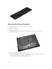
Remove the keyboard. 5. Perform the following steps as shown in Before Working Inside Your Computer. 2. c. Remove the Battery. 3. b. Remove the screws from locking tab [2]. Then, release the tabs securing the base cover. 6. Remove the access panel. 4. Flip the computer and remove the screws at the base of the computer. Flip the computer and disconnect the touchpad and power cables by pressing locking tab [1]. Removing the Palmrest Assembly 1. Follow the procedures in the illustration: a. Lift the touchpad and power cables from inside the keyboard cavity [3]. 18
Remove the keyboard. 5. Perform the following steps as shown in Before Working Inside Your Computer. 2. c. Remove the Battery. 3. b. Remove the screws from locking tab [2]. Then, release the tabs securing the base cover. 6. Remove the access panel. 4. Flip the computer and remove the screws at the base of the computer. Flip the computer and disconnect the touchpad and power cables by pressing locking tab [1]. Removing the Palmrest Assembly 1. Follow the procedures in the illustration: a. Lift the touchpad and power cables from inside the keyboard cavity [3]. 18
Owners Manual
Page 20
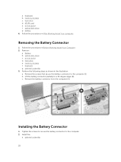
... the procedures in Before Working Inside Your Computer. 2. optical disk-drive g. memory module f. Remove the battery connector from the computer [3]. hard drive d. optical disk-drive c. keyboard g. keyboard b.
... the procedures in Before Working Inside Your Computer. 2. optical disk-drive g. memory module f. Remove the battery connector from the computer [3]. hard drive d. optical disk-drive c. keyboard g. keyboard b.
Owners Manual
Page 21
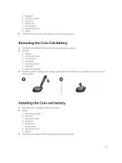
... a scribe and then pull the coin-cell battery to lock. 2. WLAN card f. access panel g. optical disk-drive h. Removing the Coin-Cell Battery 1. optical disk-drive c. keyboard c. memory module d. memory module f. Install: a. palmrest assembly b. memory module d. battery 3. hard drive e. access panel...
... a scribe and then pull the coin-cell battery to lock. 2. WLAN card f. access panel g. optical disk-drive h. Removing the Coin-Cell Battery 1. optical disk-drive c. keyboard c. memory module d. memory module f. Install: a. palmrest assembly b. memory module d. battery 3. hard drive e. access panel...
Owners Manual
Page 22
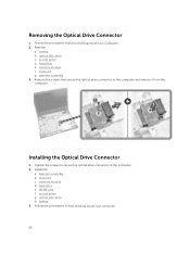
... b. Tighten the screws to secure the optical drive connector to the computer and remove it from the computer. memory module d. optical disk-drive h. memory module f. keyboard g. Removing the Optical Drive Connector 1. Follow the procedures in After Working Inside Your computer. 22...
... b. Tighten the screws to secure the optical drive connector to the computer and remove it from the computer. memory module d. optical disk-drive h. memory module f. keyboard g. Removing the Optical Drive Connector 1. Follow the procedures in After Working Inside Your computer. 22...
Owners Manual
Page 23
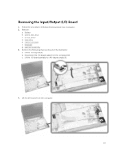
Battery b. palmrest assembly 3. b. Lift the I /0) Board 1. optical disk-drive c. access panel d. hard drive e. Lift the I /O board cable from the computer. 23 Removing the Input/Output (I /O board partially to a 45-degree angle [3]. 4. Follow the procedures in the illustration: a. memory module f. Perform the following steps as shown in Before Working Inside Your Computer. 2. keyboard g. c. Remove: a. Lift the locking tab [1]. Disconnect the I /O board from the computer [2].
Battery b. palmrest assembly 3. b. Lift the I /0) Board 1. optical disk-drive c. access panel d. hard drive e. Lift the I /O board cable from the computer. 23 Removing the Input/Output (I /O board partially to a 45-degree angle [3]. 4. Follow the procedures in the illustration: a. memory module f. Perform the following steps as shown in Before Working Inside Your Computer. 2. keyboard g. c. Remove: a. Lift the locking tab [1]. Disconnect the I /O board from the computer [2].
Owners Manual
Page 24
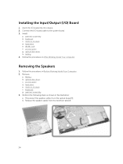
keyboard c. WLAN card f. optical disk-drive h. c. access panel. Perform the following steps as shown in Before Working Inside Your Computer. 2. b. battery 4. Remove: a. f. palmrest assembly. 3. Release the ... the I /O) Board 1. memory module d. d. Installing the Input/Output (I /O board cable to the system board. 3. access panel g. e. Follow the procedures in After Working Inside Your computer. keyboard. Insert the I/O board into the chassis. 2. Install: a. memory module. Disconnect the speaker cables from the retention tabs [2]. 24
keyboard c. WLAN card f. optical disk-drive h. c. access panel. Perform the following steps as shown in Before Working Inside Your Computer. 2. b. battery 4. Remove: a. f. palmrest assembly. 3. Release the ... the I /O) Board 1. memory module d. d. Installing the Input/Output (I /O board cable to the system board. 3. access panel g. e. Follow the procedures in After Working Inside Your computer. keyboard. Insert the I/O board into the chassis. 2. Install: a. memory module. Disconnect the speaker cables from the retention tabs [2]. 24
Owners Manual
Page 25
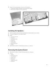
Perform the following steps as shown in Before Working Inside Your Computer. 2. Installing the Speakers 1. palmrest assembly b. keyboard c. hard drive e. Remove: a. g. Release the speaker assembly from the chassis [2]. Connect the speakers to lock .... access panel g. optical disk-drive. c. f. memory module d. battery 4. access panel. 4. Follow the procedures in the illustration: a. b. d. e. keyboard. 25 Insert the speakers into the chassis and press the retaining clips to the system board. 3. Install: a. WLAN card f. hard drive. Removing the...
Perform the following steps as shown in Before Working Inside Your Computer. 2. Installing the Speakers 1. palmrest assembly b. keyboard c. hard drive e. Remove: a. g. Release the speaker assembly from the chassis [2]. Connect the speakers to lock .... access panel g. optical disk-drive. c. f. memory module d. battery 4. access panel. 4. Follow the procedures in the illustration: a. b. d. e. keyboard. 25 Insert the speakers into the chassis and press the retaining clips to the system board. 3. Install: a. WLAN card f. hard drive. Removing the...
Owners Manual
Page 27
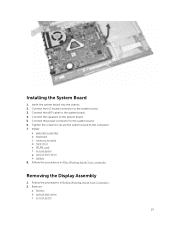
...-drive h. Remove: a. Insert the system board into the chassis. 2. Tighten the screws to secure the system board to the system board. 6. memory module d. Battery b. Install: a. keyboard c. Follow the procedures in After Working Inside Your computer. WLAN card f. hard drive e. battery 8. Follow the procedures in Before Working Inside Your Computer. 2. Connect the...
...-drive h. Remove: a. Insert the system board into the chassis. 2. Tighten the screws to secure the system board to the system board. 6. memory module d. Battery b. Install: a. keyboard c. Follow the procedures in After Working Inside Your computer. WLAN card f. hard drive e. battery 8. Follow the procedures in Before Working Inside Your Computer. 2. Connect the...
Owners Manual
Page 28
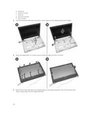
hard drive e. Unroute the WLAN cable and remove the screws that secure the display hinges to the chassis. 4. system board 3. Then, lift and remove the display hinges away from the computer. 5. d. palmrest assembly h. keyboard g. Place the display panel on a stable surface and lift the bezel from the display assembly. 28 Remove the screws that secure the display panel to the display assembly. memory module f.
hard drive e. Unroute the WLAN cable and remove the screws that secure the display hinges to the chassis. 4. system board 3. Then, lift and remove the display hinges away from the computer. 5. d. palmrest assembly h. keyboard g. Place the display panel on a stable surface and lift the bezel from the display assembly. 28 Remove the screws that secure the display panel to the display assembly. memory module f.
Owners Manual
Page 30
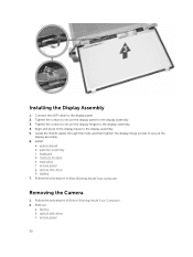
... Working Inside Your computer. system board b. optical disk-drive h. optical disk-drive c. memory module e. Connect the eDP cable to the display assembly. 3. Install: a. access panel g. keyboard d. Tighten the screws to secure the display panel to the display panel. 2. Follow the procedures in Before Working Inside Your Computer. 2.
... Working Inside Your computer. system board b. optical disk-drive h. optical disk-drive c. memory module e. Connect the eDP cable to the display assembly. 3. Install: a. access panel g. keyboard d. Tighten the screws to secure the display panel to the display panel. 2. Follow the procedures in Before Working Inside Your Computer. 2.
Owners Manual
Page 31
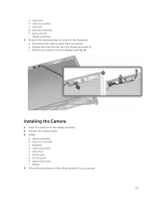
... from the display assembly [1]. Release the retention tab from the camera. c. access panel h. optical disk-drive i. keyboard g. Installing the Camera 1. display assembly b. WLAN card g. b. memory module e. Remove the camera from the display assembly [2]. battery 4. keyboard d. memory module f. Perform the following steps as shown in After Working Inside Your computer. 31 system board...
... from the display assembly [1]. Release the retention tab from the camera. c. access panel h. optical disk-drive i. keyboard g. Installing the Camera 1. display assembly b. WLAN card g. b. memory module e. Remove the camera from the display assembly [2]. battery 4. keyboard d. memory module f. Perform the following steps as shown in After Working Inside Your computer. 31 system board...
Owners Manual
Page 32
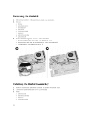
Disconnect the system fan's cable from the system board [3]. palmrest assembly c. Removing the Heatsink 1. hard drive e. memory module f. keyboard g. Perform the following steps as shown in Before Working Inside Your Computer. 2. keyboard d. Install: a. access panel d. b. system board 3. Connect the system fan's cable to the system board. 2. Follow the procedures in the illustration: a. Insert...
Disconnect the system fan's cable from the system board [3]. palmrest assembly c. Removing the Heatsink 1. hard drive e. memory module f. keyboard g. Perform the following steps as shown in Before Working Inside Your Computer. 2. keyboard d. Install: a. access panel d. b. system board 3. Connect the system fan's cable to the system board. 2. Follow the procedures in the illustration: a. Insert...
Owners Manual
Page 33
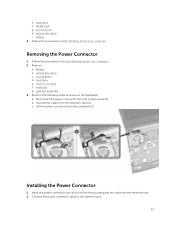
WLAN card g. Follow the procedures in the illustration: a. keyboard g. Perform the following steps as shown in After Working Inside Your computer. b. c. Installing the Power Connector 1. Battery b. palmrest assembly 3. Removing the Power Connector 1. Remove: a. Insert ...
WLAN card g. Follow the procedures in the illustration: a. keyboard g. Perform the following steps as shown in After Working Inside Your computer. b. c. Installing the Power Connector 1. Battery b. palmrest assembly 3. Removing the Power Connector 1. Remove: a. Insert ...

Owners Manual
Page 34
hard drive e. access panel g. Install: a. WLAN card f. Follow the procedures in After Working Inside Your computer. 34 battery 4. keyboard c. optical disk-drive h. 3. palmrest assembly b. memory module d.
hard drive e. access panel g. Install: a. WLAN card f. Follow the procedures in After Working Inside Your computer. 34 battery 4. keyboard c. optical disk-drive h. 3. palmrest assembly b. memory module d.
Owners Manual
Page 46
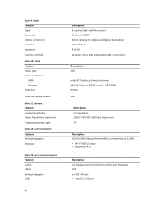
... adapter USB: 46 Description 2 channel high-definition audio Realtek ALC3234 24-bit (analog-to-digital and digital-to-analog) Intel HDA bus 2 x 2 W program menu and keyboard media-control keys Description eDP Intel HD Graphics (shared memory) NVIDIA GeForce 820M (up to 2 GB DDR3) 64 bits VGA Description HD resolution 1280 x 720...
... adapter USB: 46 Description 2 channel high-definition audio Realtek ALC3234 24-bit (analog-to-digital and digital-to-analog) Intel HDA bus 2 x 2 W program menu and keyboard media-control keys Description eDP Intel HD Graphics (shared memory) NVIDIA GeForce 820M (up to 2 GB DDR3) 64 bits VGA Description HD resolution 1280 x 720...
Owners Manual
Page 47
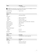
Keyboard Feature Number of keys: Description US 101, Brazil 104, UK 102, and Japan 105 Table 16. Display Feature Type Dimensions: Height Thickness Width Active area (X/Y) Maximum resolution Maximum Brightness Operating angle Refresh rate Minimum Viewing angles: Horizontal Vertical Pixel pitch 15.6 inches HD WLED 224.30 ...176; (closed) to 135° 60 Hz 40° / 40° 10° / 30° 0.252 mm x 0.252 mm Table 15. Media card reader one 3-in the documentation shipped with your computer. The ports are identified in -1 slot Table 14. Touchpad Feature Active Area: X-axis ...
Keyboard Feature Number of keys: Description US 101, Brazil 104, UK 102, and Japan 105 Table 16. Display Feature Type Dimensions: Height Thickness Width Active area (X/Y) Maximum resolution Maximum Brightness Operating angle Refresh rate Minimum Viewing angles: Horizontal Vertical Pixel pitch 15.6 inches HD WLED 224.30 ...176; (closed) to 135° 60 Hz 40° / 40° 10° / 30° 0.252 mm x 0.252 mm Table 15. Media card reader one 3-in the documentation shipped with your computer. The ports are identified in -1 slot Table 14. Touchpad Feature Active Area: X-axis ...


