Owners Manual
Page 3
... Tools...8 Turning Off Your Computer...8 After Working Inside Your Computer 9 2 Removing and Installing Components 10 Removing the Battery...10 Installing the Battery...11 Removing the Optical Drive...11 Installing the Optical Drive...12 Removing the Access Panel...12 Installing the Access Panel...13 Removing the Hard Drive...13 Installing the Hard Drive...14 Removing the Memory Module...14 Installing the Memory Module...14 Removing the WLAN Card...15 Installing the WLAN Card...15 Removing the Keyboard...15 Installing the Keyboard...16 Removing the Palmrest Assembly...18 Installing the...
... Tools...8 Turning Off Your Computer...8 After Working Inside Your Computer 9 2 Removing and Installing Components 10 Removing the Battery...10 Installing the Battery...11 Removing the Optical Drive...11 Installing the Optical Drive...12 Removing the Access Panel...12 Installing the Access Panel...13 Removing the Hard Drive...13 Installing the Hard Drive...14 Removing the Memory Module...14 Installing the Memory Module...14 Removing the WLAN Card...15 Installing the WLAN Card...15 Removing the Keyboard...15 Installing the Keyboard...16 Removing the Palmrest Assembly...18 Installing the...
Owners Manual
Page 4
Removing the Display Assembly...27 Installing the Display Assembly...30 Removing the Camera...30 Installing the Camera...31 Removing the Heatsink...32 Installing the Heatsink Assembly...32 Removing the Power Connector...33 Installing the Power Connector...33 3 System Setup...35 Boot Sequence...35 Navigation Keys...35 System Setup Options...36 Updating the BIOS ...40 System and Setup Password...40 Assigning a System Password and Setup Password 41 Deleting or Changing an Existing System and/or Setup Password 41 4 Diagnostics...43 Enhanced...
Removing the Display Assembly...27 Installing the Display Assembly...30 Removing the Camera...30 Installing the Camera...31 Removing the Heatsink...32 Installing the Heatsink Assembly...32 Removing the Power Connector...33 Installing the Power Connector...33 3 System Setup...35 Boot Sequence...35 Navigation Keys...35 System Setup Options...36 Updating the BIOS ...40 System and Setup Password...40 Assigning a System Password and Setup Password 41 Deleting or Changing an Existing System and/or Setup Password 41 4 Diagnostics...43 Enhanced...
Owners Manual
Page 7
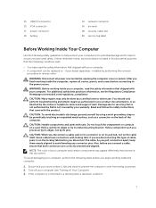
...: Handle components and cards with locking tabs; Do not touch the components or contacts on the cable itself. NOTE: The color of the computer. WARNING: Disconnect all covers, panels, and screws before you pull connectors apart, keep them evenly aligned to help to a docking device (docked), undock it. 7 After you disconnect the cable. Damage due to the power source. CAUTION...
...: Handle components and cards with locking tabs; Do not touch the components or contacts on the cable itself. NOTE: The color of the computer. WARNING: Disconnect all covers, panels, and screws before you pull connectors apart, keep them evenly aligned to help to a docking device (docked), undock it. 7 After you disconnect the cable. Damage due to the power source. CAUTION...
Owners Manual
Page 8
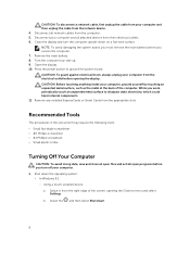
... the screen, opening the display. Using a touch-enabled device: a. b. Turn the computer top-side up. 9. While you service the computer. 7. CAUTION: To disconnect a network cable, first unplug the cable from your computer and all attached devices from their electrical outlets. 6. Remove any installed ExpressCards or Smart Cards from the computer. 5. Disconnect your computer and then unplug the cable from the right edge of the computer. Press the power button...
... the screen, opening the display. Using a touch-enabled device: a. b. Turn the computer top-side up. 9. While you service the computer. 7. CAUTION: To disconnect a network cable, first unplug the cable from your computer and all attached devices from their electrical outlets. 6. Remove any installed ExpressCards or Smart Cards from the computer. 5. Disconnect your computer and then unplug the cable from the right edge of the computer. Press the power button...
Owners Manual
Page 9
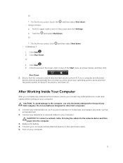
... a port replicator or media base, and replace any replacement procedure, ensure you shut down your operating system, press and hold the power button for other Dell computers. 1. Replace the battery. 4. Or * On the Home screen, touch the - Click Shut Down. or 1. Do not use only the battery designed for this particular Dell computer. Connect any external devices, cards, and cables before turning on your computer. Turn on your computer. 9 Click Start . 2. CAUTION: To connect a network cable...
... a port replicator or media base, and replace any replacement procedure, ensure you shut down your operating system, press and hold the power button for other Dell computers. 1. Replace the battery. 4. Or * On the Home screen, touch the - Click Shut Down. or 1. Do not use only the battery designed for this particular Dell computer. Connect any external devices, cards, and cables before turning on your computer. Turn on your computer. 9 Click Start . 2. CAUTION: To connect a network cable...
Owners Manual
Page 14
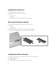
.... 2. Follow the procedures in After Working Inside Your computer. 14 Remove: a. Follow the procedures in Before Working Inside Your Computer. 2. Follow the procedures in After Working Inside Your computer. Install the access panel. 3. Pry the securing clips away from its socket on the system board. Slide the hard drive into the socket and press to the chassis. 3. Installing the Memory Module 1. Install the battery. 4. Install: a. access panel b. Installing the Hard Drive 1.
.... 2. Follow the procedures in After Working Inside Your computer. 14 Remove: a. Follow the procedures in Before Working Inside Your Computer. 2. Follow the procedures in After Working Inside Your computer. Install the access panel. 3. Pry the securing clips away from its socket on the system board. Slide the hard drive into the socket and press to the chassis. 3. Installing the Memory Module 1. Install the battery. 4. Install: a. access panel b. Installing the Hard Drive 1.
Owners Manual
Page 21
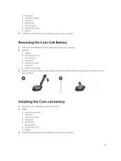
... WLAN card f. memory module f. palmrest assembly 3. Insert the coin-cell battery and press to remove it from the computer. keyboard c. access panel g. optical disk-drive h. Follow the procedures in After Working Inside Your computer. 21 Remove: a. Battery b. memory module d. optical disk-drive h. access panel g. keyboard g. Push the coin-cell release latch using a scribe and then pull the coin-cell battery to lock. 2. access panel d. Follow the procedures in Before Working Inside Your Computer. 2. b. hard drive e. Removing the Coin-Cell Battery...
... WLAN card f. memory module f. palmrest assembly 3. Insert the coin-cell battery and press to remove it from the computer. keyboard c. access panel g. optical disk-drive h. Follow the procedures in After Working Inside Your computer. 21 Remove: a. Battery b. memory module d. optical disk-drive h. access panel g. keyboard g. Push the coin-cell release latch using a scribe and then pull the coin-cell battery to lock. 2. access panel d. Follow the procedures in Before Working Inside Your Computer. 2. b. hard drive e. Removing the Coin-Cell Battery...
Owners Manual
Page 24
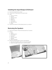
... Your Computer. 2. memory module d. optical disk-drive h. battery 4. Battery. e. Release the speaker cables from the system board [1]. access panel g. c. memory module. Follow the procedures in the illustration: a. optical disk-drive. palmrest assembly. 3. keyboard c. WLAN card f. Follow the procedures in After Working Inside Your computer. f. keyboard. b. hard drive. g. palmrest assembly b. Insert the I /O) Board 1. Installing the Input/Output (I /O board into the chassis. 2. Connect the I/O board cable to the system board. 3. Disconnect the...
... Your Computer. 2. memory module d. optical disk-drive h. battery 4. Battery. e. Release the speaker cables from the system board [1]. access panel g. c. memory module. Follow the procedures in the illustration: a. optical disk-drive. palmrest assembly. 3. keyboard c. WLAN card f. Follow the procedures in After Working Inside Your computer. f. keyboard. b. hard drive. g. palmrest assembly b. Insert the I /O) Board 1. Installing the Input/Output (I /O board into the chassis. 2. Connect the I/O board cable to the system board. 3. Disconnect the...
Owners Manual
Page 25
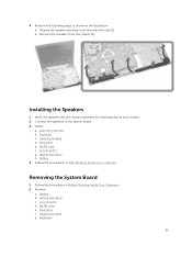
... to lock in the illustration: a. keyboard c. battery 4. Follow the procedures in Before Working Inside Your Computer. 2. Battery. access panel. d. keyboard. 25 Install: a. access panel g. e. g. 4. b. Installing the Speakers 1. hard drive e. Follow the procedures in After Working Inside Your computer. Insert the speakers into the chassis and press the retaining clips to the system board. 3. Remove: a. b. memory module. WLAN card f. hard drive. memory module d. Release the speaker assembly from the chassis [2]. optical disk-drive...
... to lock in the illustration: a. keyboard c. battery 4. Follow the procedures in Before Working Inside Your Computer. 2. Battery. access panel. d. keyboard. 25 Install: a. access panel g. e. g. 4. b. Installing the Speakers 1. hard drive e. Follow the procedures in After Working Inside Your computer. Insert the speakers into the chassis and press the retaining clips to the system board. 3. Remove: a. b. memory module. WLAN card f. hard drive. memory module d. Release the speaker assembly from the chassis [2]. optical disk-drive...
Owners Manual
Page 27
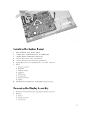
... b. memory module d. WLAN card f. Follow the procedures in Before Working Inside Your Computer. 2. access panel 27 Connect the power connector to the system board. 5. Install: a. Removing the Display Assembly 1. Battery b. access panel g. Connect the I/O board connector to the computer. 7. hard drive e. battery 8. optical disk-drive h. Installing the System Board 1. Remove: a. Tighten the screws to secure the system board to the system board. 3. Connect the eDP cable to the system board. 4. Insert the system board into the chassis. 2. keyboard...
... b. memory module d. WLAN card f. Follow the procedures in Before Working Inside Your Computer. 2. access panel 27 Connect the power connector to the system board. 5. Install: a. Removing the Display Assembly 1. Battery b. access panel g. Connect the I/O board connector to the computer. 7. hard drive e. battery 8. optical disk-drive h. Installing the System Board 1. Remove: a. Tighten the screws to secure the system board to the system board. 3. Connect the eDP cable to the system board. 4. Insert the system board into the chassis. 2. keyboard...
Owners Manual
Page 29
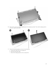
6. c. Remove the screws securing the display panel to access the cables underneath. 7. b. Then, flip the display panel to the display assembly. Perform the following steps as shown in the illustration: a. Lift the eDP cable from the computer [3]. 29 Disconnect the eDP cable. Remove the display panel from the computer [1].
6. c. Remove the screws securing the display panel to access the cables underneath. 7. b. Then, flip the display panel to the display assembly. Perform the following steps as shown in the illustration: a. Lift the eDP cable from the computer [3]. 29 Disconnect the eDP cable. Remove the display panel from the computer [1].
Owners Manual
Page 30
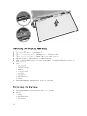
... 2. Battery b. Connect the eDP cable to the display assembly. 5. Align and press in the display bezel to the display panel. 2. Tighten the screws to secure the display panel to the display assembly. 4. Install: a. memory module e. system board b. optical disk-drive h. Removing the Camera 1. Follow the procedures in After Working Inside Your computer. access panel 30 palmrest assembly c. Tighten the screws to secure the display hinges to the display assembly. 3. access panel g. battery 7. Remove: a. hard drive f. optical disk-drive c. Guide the WLAN cables...
... 2. Battery b. Connect the eDP cable to the display assembly. 5. Align and press in the display bezel to the display panel. 2. Tighten the screws to secure the display panel to the display assembly. 4. Install: a. memory module e. system board b. optical disk-drive h. Removing the Camera 1. Follow the procedures in After Working Inside Your computer. access panel 30 palmrest assembly c. Tighten the screws to secure the display hinges to the display assembly. 3. access panel g. battery 7. Remove: a. hard drive f. optical disk-drive c. Guide the WLAN cables...
Owners Manual
Page 31
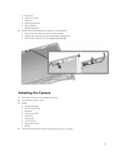
... Working Inside Your computer. 31 Installing the Camera 1. memory module e. hard drive e. Disconnect the camera cable from the display assembly [2]. Remove the camera from the camera. Connect the camera cable. 3. access panel h. keyboard g. b. Install: a. keyboard d. Insert the camera into the display assembly. 2. palmrest assembly c. WLAN card g. memory module f. Release the retention tab from the display assembly [1]. c. display assembly 3. display assembly b. optical disk-drive i. d. palmrest assembly h. system board i. hard drive f. battery...
... Working Inside Your computer. 31 Installing the Camera 1. memory module e. hard drive e. Disconnect the camera cable from the display assembly [2]. Remove the camera from the camera. Connect the camera cable. 3. access panel h. keyboard g. b. Install: a. keyboard d. Insert the camera into the display assembly. 2. palmrest assembly c. WLAN card g. memory module f. Release the retention tab from the display assembly [1]. c. display assembly 3. display assembly b. optical disk-drive i. d. palmrest assembly h. system board i. hard drive f. battery...
Owners Manual
Page 33
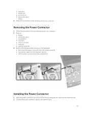
hard drive f. access panel h. battery 4. Remove: a. hard drive e. Disconnect the power connector from the computer [3]. b. Connect the power connector cable to the system board. 33 Removing the Power Connector 1. memory module f. c. Perform the following steps as shown in After Working Inside Your computer. Lift the power connector from the system board [1]. Follow the procedures in the illustration: a. access panel d. keyboard g. Unroute the cable from the retention clips [2]. optical disk-drive c. Insert the power connector into its slot on the...
hard drive f. access panel h. battery 4. Remove: a. hard drive e. Disconnect the power connector from the computer [3]. b. Connect the power connector cable to the system board. 33 Removing the Power Connector 1. memory module f. c. Perform the following steps as shown in After Working Inside Your computer. Lift the power connector from the system board [1]. Follow the procedures in the illustration: a. access panel d. keyboard g. Unroute the cable from the retention clips [2]. optical disk-drive c. Insert the power connector into its slot on the...
Owners Manual
Page 35
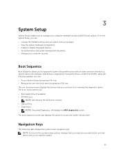
... boot-menu options are recorded but do not take effect until you re-start the system. 35 From the System Setup, you can: • Change the NVRAM settings after you add or remove hardware • View the system hardware configuration • Enable or disable integrated devices • Set performance and power management thresholds • Manage your computer hardware and specify BIOS‐level options. Navigation Keys The following table displays the system setup navigation keys...
... boot-menu options are recorded but do not take effect until you re-start the system. 35 From the System Setup, you can: • Change the NVRAM settings after you add or remove hardware • View the system hardware configuration • Enable or disable integrated devices • Set performance and power management thresholds • Manage your computer hardware and specify BIOS‐level options. Navigation Keys The following table displays the system setup navigation keys...
Owners Manual
Page 38
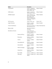
... key . Enables or disables external USB ports. Default: Enabled Enables or disables optical drive. These fields let you enable or disable various on - Default: AHCI Enables or disables adapter warnings. Default: Enabled Enables or disables WLAN. Option Integrated NIC USB Emulation USB Wake Support SATA Operation Adapter Warnings Function Key Behavior Battery Health Miscellaneous Devices External USB Ports Microphone Camera Internal Bluetooth Internal WLAN Media Card Reader Optical Drive Boot Disable USB debug Description Enable or disable the Default: Enabled power...
... key . Enables or disables external USB ports. Default: Enabled Enables or disables optical drive. These fields let you enable or disable various on - Default: AHCI Enables or disables adapter warnings. Default: Enabled Enables or disables WLAN. Option Integrated NIC USB Emulation USB Wake Support SATA Operation Adapter Warnings Function Key Behavior Battery Health Miscellaneous Devices External USB Ports Microphone Camera Internal Bluetooth Internal WLAN Media Card Reader Optical Drive Boot Disable USB debug Description Enable or disable the Default: Enabled power...
Owners Manual
Page 39
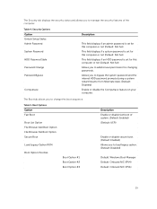
...Default: Windows Boot Manager Default: Onboard NIC (IPV4) Default: Onboard NIC (IPV6) 39 Boot Options Option Fast Boot Boot List Option File Browser Add Boot Option File Browser Del Boot Option Secure Boot Load Legacy Option ROM Boot Option Priorities Boot Option #1 Boot Option #2 Boot Option #3 Description Enable or disable fast boot of the computer. Table 4. Table 5. Allows you to manage the security features of system. (Default: Enabled) (Default: UEFI) Enable or disable secure boot. (Default: Enabled) Allows you to change the boot sequence. The Security tab displays...
...Default: Windows Boot Manager Default: Onboard NIC (IPV4) Default: Onboard NIC (IPV6) 39 Boot Options Option Fast Boot Boot List Option File Browser Add Boot Option File Browser Del Boot Option Secure Boot Load Legacy Option ROM Boot Option Priorities Boot Option #1 Boot Option #2 Boot Option #3 Description Enable or disable fast boot of the computer. Table 4. Table 5. Allows you to manage the security features of system. (Default: Enabled) (Default: UEFI) Enable or disable secure boot. (Default: Enabled) Allows you to change the boot sequence. The Security tab displays...
Owners Manual
Page 40
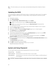
... charged and connected to a power outlet 1. For laptops, ensure that you are unable to your system. If you must enter to access and make changes to install the updated BIOS settings on to locate or find your computer. On the Drivers and Downloads screen, under the Operating System drop-down list, select BIOS. 9. Select your preferred download method in the Please select your computer. 5. The File Download window appears. 11. Password Type System password Setup password Description Password...
... charged and connected to a power outlet 1. For laptops, ensure that you are unable to your system. If you must enter to access and make changes to install the updated BIOS settings on to locate or find your computer. On the Drivers and Downloads screen, under the Operating System drop-down list, select BIOS. 9. Select your preferred download method in the Please select your computer. 5. The File Download window appears. 11. Password Type System password Setup password Description Password...
Owners Manual
Page 43
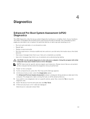
... terminal when the diagnostic tests are displayed. On the boot menu screen, select the Diagnostics option. The diagnostics starts running the tests on the computer. 2. Select the device from the left pane and click Run Tests. 6. Note the error code and contact Dell. 43 Power-on all devices detected in an interactive mode • Repeat tests • Display or save test results • Run...
... terminal when the diagnostic tests are displayed. On the boot menu screen, select the Diagnostics option. The diagnostics starts running the tests on the computer. 2. Select the device from the left pane and click Run Tests. 6. Note the error code and contact Dell. 43 Power-on all devices detected in an interactive mode • Repeat tests • Display or save test results • Run...
Owners Manual
Page 46
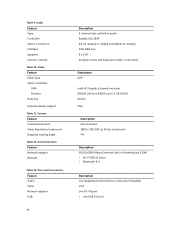
... 1280 x 720 (HD) at 30 fps (maximum) 74° Description 10/100/1000 Mbps Ethernet LAN on Motherboard (LOM) • Wi-Fi 802.11 b/g/n • Bluetooth 4.0 Description one headphone/microphone combo port (headset) VGA one RJ-45 port • one USB 3.0 port Camera Feature Camera Resolution Video Resolution (maximum) Diagonal viewing angle Table 12. Video Feature Video type Video Controller: UMA Discrete Data bus: External display support Table 11.
... 1280 x 720 (HD) at 30 fps (maximum) 74° Description 10/100/1000 Mbps Ethernet LAN on Motherboard (LOM) • Wi-Fi 802.11 b/g/n • Bluetooth 4.0 Description one headphone/microphone combo port (headset) VGA one RJ-45 port • one USB 3.0 port Camera Feature Camera Resolution Video Resolution (maximum) Diagonal viewing angle Table 12. Video Feature Video type Video Controller: UMA Discrete Data bus: External display support Table 11.


