
Hardware Manual
Page 14
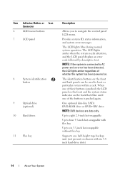
... with six 3.5inch hard-drive slots) 14 About Your System The LCD lights amber when the system needs attention, and the LCD panel displays an error code followed by descriptive text. Item Indicator, Button, or Icon Connector 6 LCD menu buttons 7 LCD panel 8 System identification button 9 Optical drive (optional) 10 ...swappable without flex bay Supports one half-height tape backup unit (not present on chassis with flex bay Up to AC power and an error has been detected, the LCD lights amber regardless of whether the system has been powered on the front and back panels can be used...
... with six 3.5inch hard-drive slots) 14 About Your System The LCD lights amber when the system needs attention, and the LCD panel displays an error code followed by descriptive text. Item Indicator, Button, or Icon Connector 6 LCD menu buttons 7 LCD panel 8 System identification button 9 Optical drive (optional) 10 ...swappable without flex bay Supports one half-height tape backup unit (not present on chassis with flex bay Up to AC power and an error has been detected, the LCD lights amber regardless of whether the system has been powered on the front and back panels can be used...
Hardware Manual
Page 15
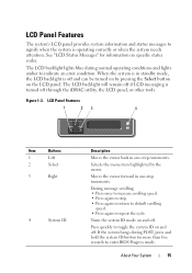
The LCD backlight will remain off if LCD messaging is turned off . Press quickly to indicate an error condition. The LCD backlight lights blue during POST, press and hold the system ID button for information on and off through the iDRAC utility, the ... 1 23 4 Item Buttons 1 Left 2 Select 3 Right 4 System ID Description Moves the cursor back in one -step increments. Turns the system ID mode on specific status codes. About Your System 15 Selects the menu item highlighted by pressing the Select button on the LCD panel. When the system is in standby mode...
The LCD backlight will remain off if LCD messaging is turned off . Press quickly to indicate an error condition. The LCD backlight lights blue during POST, press and hold the system ID button for information on and off through the iDRAC utility, the ... 1 23 4 Item Buttons 1 Left 2 Select 3 Right 4 System ID Description Moves the cursor back in one -step increments. Turns the system ID mode on specific status codes. About Your System 15 Selects the menu item highlighted by pressing the Select button on the LCD panel. When the system is in standby mode...
Hardware Manual
Page 21
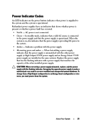
... that has the flashing indicator with the other installed power supply. Redundant power supplies have an indicator that shows whether power is operational. Power Indicator Codes An LED indicator on , also indicates that the power supply is not connected. • Green - In standby mode, indicates that a valid AC source is connected... that matches the capacity of the other power supply (a High Output 870-W power supply and an Energy Smart 570-W power supply are installed in an error condition and unexpected system shutdown.
... that has the flashing indicator with the other installed power supply. Redundant power supplies have an indicator that shows whether power is operational. Power Indicator Codes An LED indicator on , also indicates that the power supply is not connected. • Green - In standby mode, indicates that a valid AC source is connected... that matches the capacity of the other power supply (a High Output 870-W power supply and an Energy Smart 570-W power supply are installed in an error condition and unexpected system shutdown.
Hardware Manual
Page 23
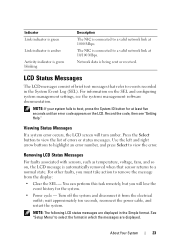
... a valid network link at 1000 Mbps. NOTE: If your system fails to view the error. Viewing Status Messages If a system error occurs, the LCD screen will lose the event history for at least five seconds until an error code appears on , the LCD message is automatically removed when that refer to events recorded in...
... a valid network link at 1000 Mbps. NOTE: If your system fails to view the error. Viewing Status Messages If a system error occurs, the LCD screen will lose the event history for at least five seconds until an error code appears on , the LCD message is automatically removed when that refer to events recorded in...
Hardware Manual
Page 24
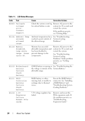
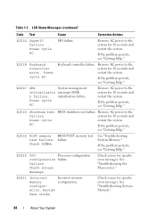
..., see "Troubleshooting Expansion Cards." 24 About Your System Remove AC power to the for 10 seconds and restart the system. LCD Status Messages Code Text E1000 Failsafe voltage error. Contact support. Power cycle AC. Check battery. Memory has exceeded allowable temperature and has been disabled to prevent damage to thermal issues. If...
..., see "Troubleshooting Expansion Cards." 24 About Your System Remove AC power to the for 10 seconds and restart the system. LCD Status Messages Code Text E1000 Failsafe voltage error. Contact support. Power cycle AC. Check battery. Memory has exceeded allowable temperature and has been disabled to prevent damage to thermal issues. If...
Hardware Manual
Page 26
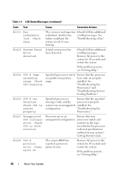
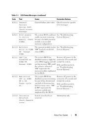
...properly system is no longer fan Check LCD for additional scrolling messages. E141F CPU # protocol error. Table 1-1. Check fans. See failure would put the "Troubleshooting a Fan." detected. ... The system is in the processor revision. E1410 System Fatal A fatal system error has Error been detected. Specified processor is Ensure that your system's Getting Started Guide. ...cycle AC. The system BIOS has reported a processor protocol error. "Troubleshooting the Processor(s)." E1418 CPU # not detected. heating. E1414 CPU # temp...
...properly system is no longer fan Check LCD for additional scrolling messages. E141F CPU # protocol error. Table 1-1. Check fans. See failure would put the "Troubleshooting a Fan." detected. ... The system is in the processor revision. E1410 System Fatal A fatal system error has Error been detected. Specified processor is Ensure that your system's Getting Started Guide. ...cycle AC. The system BIOS has reported a processor protocol error. "Troubleshooting the Processor(s)." E1418 CPU # not detected. heating. E1414 CPU # temp...
Hardware Manual
Page 27
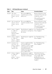
...for the specified it has lost AC power. A power supply fan failure, an over-temperature condition, or power supply communication error has caused the predictive warning of an impending power supply failure. About Your System 27 Power cycle AC. If the problem ... Predictive failure on Power Supply # (### W). If the problem persists, see "Troubleshooting Power Supplies." LCD Status Messages (continued) Code Text Cause Corrective Actions E1420 CPU Bus The system BIOS has parity error. Remove AC power to the system for 10 seconds and restart the system. Power Supplies...
...for the specified it has lost AC power. A power supply fan failure, an over-temperature condition, or power supply communication error has caused the predictive warning of an impending power supply failure. About Your System 27 Power cycle AC. If the problem ... Predictive failure on Power Supply # (### W). If the problem persists, see "Troubleshooting Power Supplies." LCD Status Messages (continued) Code Text Cause Corrective Actions E1420 CPU Bus The system BIOS has parity error. Remove AC power to the system for 10 seconds and restart the system. Power Supplies...
Hardware Manual
Page 28
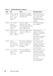
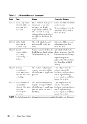
LCD Status Messages (continued) Code Text Cause Corrective Actions E1620 Power Supply # (### W) AC power error. Specified power supply's AC input is no longer Power Supplies." redundant. PSU2 = ### W. See the Technical Specifications outlined in the Mismatch. The system configuration requires... off power to the system for 10 seconds and restart the system. Review & clear SEL. The system BIOS has reported an I /O channel check error. Check the SEL for the specified power supply. Check the AC power source for more power than the power supplies can provide, even with matching...
LCD Status Messages (continued) Code Text Cause Corrective Actions E1620 Power Supply # (### W) AC power error. Specified power supply's AC input is no longer Power Supplies." redundant. PSU2 = ### W. See the Technical Specifications outlined in the Mismatch. The system configuration requires... off power to the system for 10 seconds and restart the system. Review & clear SEL. The system BIOS has reported an I /O channel check error. Check the SEL for the specified power supply. Check the AC power source for more power than the power supplies can provide, even with matching...
Hardware Manual
Page 29
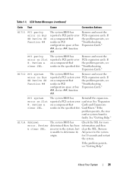
... problem persists, see "Troubleshooting Expansion Cards." LCD Status Messages (continued) Code Text Cause Corrective Actions E1711 PCI parity error on Bus ## Device ## Function ## The system BIOS has reported a PCI parity error on a component that the problem persists, see resides in the specified ...." See "Expansion on a component that resides in PCI configuration space at bus Expansion Cards." ##, device ##, function ##. E1714 Unknown error. If the problem persists, the riser card or system board is unable to the system for more information and then clear the SEL...
... problem persists, see "Troubleshooting Expansion Cards." LCD Status Messages (continued) Code Text Cause Corrective Actions E1711 PCI parity error on Bus ## Device ## Function ## The system BIOS has reported a PCI parity error on a component that the problem persists, see resides in the specified ...." See "Expansion on a component that resides in PCI configuration space at bus Expansion Cards." ##, device ##, function ##. E1714 Unknown error. If the problem persists, the riser card or system board is unable to the system for more information and then clear the SEL...

Hardware Manual
Page 30
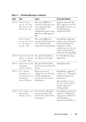
... E1716 Chipset IERR Bus ## Dev ## Function ##. The system BIOS has reported a chipset internal error that the specified processor has had an internal error. Remove AC power to the system for 10 seconds, and restart the system. E1717 CPU # internal error. The system BIOS has determined that resides in the system. Check the SEL...Remove AC power to the system for more information, and then clear the SEL. If the problem persists, see "Getting Help." LCD Status Messages (continued) Code Text Cause Corrective Actions E1715 Fatal I/O Error. Table 1-1. Review & clear SEL.
... E1716 Chipset IERR Bus ## Dev ## Function ##. The system BIOS has reported a chipset internal error that the specified processor has had an internal error. Remove AC power to the system for 10 seconds, and restart the system. E1717 CPU # internal error. The system BIOS has determined that resides in the system. Check the SEL...Remove AC power to the system for more information, and then clear the SEL. If the problem persists, see "Getting Help." LCD Status Messages (continued) Code Text Cause Corrective Actions E1715 Fatal I/O Error. Table 1-1. Review & clear SEL.
Hardware Manual
Page 31
LCD Status Messages (continued) Code Text Cause Corrective Actions E171F PCIe fatal error on Bus ## Device ## Function ## The system BIOS has reported a PCIe fatal error on a component that Cards and Expansion- Remove and reseat the PCIe expansion cards. PCIe fatal error on a component that resides ... are missing. Reinstall the expansioncard riser. About Your System 31 The system BIOS has Reinstall the expansion- reported a PCIe fatal error card riser. Card Risers." system. See "Expansion on Slot #. See "Troubleshooting a Hard Drive." If the problem persists, the...
LCD Status Messages (continued) Code Text Cause Corrective Actions E171F PCIe fatal error on Bus ## Device ## Function ## The system BIOS has reported a PCIe fatal error on a component that Cards and Expansion- Remove and reseat the PCIe expansion cards. PCIe fatal error on a component that resides ... are missing. Reinstall the expansioncard riser. About Your System 31 The system BIOS has Reinstall the expansion- reported a PCIe fatal error card riser. Card Risers." system. See "Expansion on Slot #. See "Troubleshooting a Hard Drive." If the problem persists, the...
Hardware Manual
Page 32
LCD Status Messages (continued) Code Text Cause Corrective Actions E1A14 SAS cable A failure. If the problem persists, replace cable. E1A1D Control panel USB cable not detected. If the ... Your System If the problem persists, see "Getting Help." See "Troubleshooting System Memory." SAS cable A is missing or bad. If the problem persists, replace cable. Error failure. Check connection. Reseat the cable. See "Installing Memory Modules" or "Troubleshooting System Memory." Table 1-1. E1A15 SAS cable B failure. Check connection. SAS cable B...
LCD Status Messages (continued) Code Text Cause Corrective Actions E1A14 SAS cable A failure. If the problem persists, replace cable. E1A1D Control panel USB cable not detected. If the ... Your System If the problem persists, see "Getting Help." See "Troubleshooting System Memory." SAS cable A is missing or bad. If the problem persists, replace cable. Error failure. Check connection. Reseat the cable. See "Installing Memory Modules" or "Troubleshooting System Memory." Table 1-1. E1A15 SAS cable B failure. Check connection. SAS cable B...
Hardware Manual
Page 33
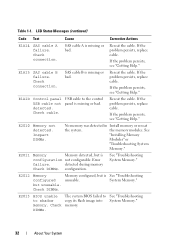
...Remove AC power to the system for 10 seconds and restart the system. Timer refresh failure. CMOS RAM not functioning properly. DMA controller failure. Interrupt controller failure. E2017 Timer refresh failure. Remove AC power ...the system. Power cycle AC. If the problem persists, see "Getting Help." E2019 Parity error. Power cycle AC. E2018 Programmable Timer error. Table 1-1. Remove AC power to the system for 10 seconds and restart the system. If...seconds and restart the system. LCD Status Messages (continued) Code Text Cause Corrective Actions E2014 CMOS...
...Remove AC power to the system for 10 seconds and restart the system. Timer refresh failure. CMOS RAM not functioning properly. DMA controller failure. Interrupt controller failure. E2017 Timer refresh failure. Remove AC power ...the system. Power cycle AC. If the problem persists, see "Getting Help." E2019 Parity error. Power cycle AC. E2018 Programmable Timer error. Table 1-1. Remove AC power to the system for 10 seconds and restart the system. If...seconds and restart the system. LCD Status Messages (continued) Code Text Cause Corrective Actions E2014 CMOS...
Hardware Manual
Page 34
...E201D Shutdown test failure. Check DIMMs. See "Troubleshooting System Memory." Check screen message. Check screen for specific error messages. Check screen for specific error messages. Remove AC power to the system for 10 seconds and restart the system. If the problem persists...configuration configuration failure. Review User Guide. SIO failure. LCD Status Messages (continued) Code Text Cause Corrective Actions E201A SuperIO failure. Power cycle AC. E201B Keyboard Controller error. Power cycle AC. Remove AC power to the system for 10 seconds and restart...
...E201D Shutdown test failure. Check DIMMs. See "Troubleshooting System Memory." Check screen message. Check screen for specific error messages. Check screen for specific error messages. Remove AC power to the system for 10 seconds and restart the system. If the problem persists...configuration configuration failure. Review User Guide. SIO failure. LCD Status Messages (continued) Code Text Cause Corrective Actions E201A SuperIO failure. Power cycle AC. E201B Keyboard Controller error. Power cycle AC. Remove AC power to the system for 10 seconds and restart...
Hardware Manual
Page 35
... module implicated by the BIOS. one half of a faulty memory module or an invalid memory configuration. LCD Status Messages (continued) Code Text Cause Corrective Actions E2022 General failure during POST. error (MBE). I1910 Intrusion detected. Check DIMMs. The system BIOS could not See "Troubleshooting enable memory mirroring System Memory." E2023 BIOS unable...
... module implicated by the BIOS. one half of a faulty memory module or an invalid memory configuration. LCD Status Messages (continued) Code Text Cause Corrective Actions E2022 General failure during POST. error (MBE). I1910 Intrusion detected. Check DIMMs. The system BIOS could not See "Troubleshooting enable memory mirroring System Memory." E2023 BIOS unable...
Hardware Manual
Page 36
LCD Status Messages (continued) Code Text Cause Corrective Actions I1911 LCD Log Full. Review & clear log. ... what the power supply can provide, but it can provide. A maximum of events and is full of ten error messages can display sequentially on the LCD. I1912 SEL full. The system configuration requires more information and then clear...24hr. Check PSU and config. Table 1-1. The eleventh message instructs the user to review all Errors. hours of an abbreviation or acronym used in this table, see "Glossary." 36 About Your System See "Installing a RAID...
LCD Status Messages (continued) Code Text Cause Corrective Actions I1911 LCD Log Full. Review & clear log. ... what the power supply can provide, but it can provide. A maximum of events and is full of ten error messages can display sequentially on the LCD. I1912 SEL full. The system configuration requires more information and then clear...24hr. Check PSU and config. Table 1-1. The eleventh message instructs the user to review all Errors. hours of an abbreviation or acronym used in this table, see "Glossary." 36 About Your System See "Installing a RAID...
Hardware Manual
Page 51
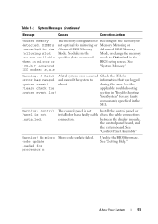
... Modules in the Advanced ECC Memory Advanced ECC Memory following slot Mode. during the error. See the Please check the applicable troubleshooting system event log! No micro Micro code update failed. mode to information that was logged system reset! ECC modes: x,x,x ...Warning: A fatal A fatal system error occurred Check the SEL for detected. Warning! Warning: Control Panel is...
... Modules in the Advanced ECC Memory Advanced ECC Memory following slot Mode. during the error. See the Please check the applicable troubleshooting system event log! No micro Micro code update failed. mode to information that was logged system reset! ECC modes: x,x,x ...Warning: A fatal A fatal system error occurred Check the SEL for detected. Warning! Warning: Control Panel is...
Hardware Manual
Page 197
...random-access memory. service tag - Allows hard drives to report errors and failures to I/O devices. Symmetric multiprocessing. A standard interface ...system that allows a network manager to identify it when you call Dell for peripherals, and various ROM chips. SNMP - Solid State Drives....The amount of space used by setting features such as the processor(s), RAM, controllers for technical support. system board - SCSI - SDDC -... with a 9-pin connector that allows you change them again. See RAM. Disk striping writes data across three or more processors connected via a...
...random-access memory. service tag - Allows hard drives to report errors and failures to I/O devices. Symmetric multiprocessing. A standard interface ...system that allows a network manager to identify it when you call Dell for peripherals, and various ROM chips. SNMP - Solid State Drives....The amount of space used by setting features such as the processor(s), RAM, controllers for technical support. system board - SCSI - SDDC -... with a 9-pin connector that allows you change them again. See RAM. Disk striping writes data across three or more processors connected via a...
Technical Guide
Page 20
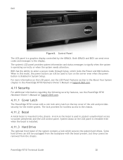
...Features section in the About Your System chapter in the PowerEdge R710 Hardware Owner's Manual on Support.Dell.com. 4.11 Security For additional information regarding the following security features, see the PowerEdge R710 Hardware Owner's Manual on Support.Dell.com. 4.11.1 Cover Latch The PowerEdge R710 comes with the bezel present, but they cannot be used... from the chassis. When in System Setup. Control Panel The LCD panel is disabled in this mode, the power button can send error codes and messages to enter a secure mode through Setup, which secures the system hard drives.
...Features section in the About Your System chapter in the PowerEdge R710 Hardware Owner's Manual on Support.Dell.com. 4.11 Security For additional information regarding the following security features, see the PowerEdge R710 Hardware Owner's Manual on Support.Dell.com. 4.11.1 Cover Latch The PowerEdge R710 comes with the bezel present, but they cannot be used... from the chassis. When in System Setup. Control Panel The LCD panel is disabled in this mode, the power button can send error codes and messages to enter a secure mode through Setup, which secures the system hard drives.
Technical Guide
Page 36
Dell 9 BIOS 9.1 Overview The R710 BIOS is based on the Dell BIOS core, supporting the following features: Intel® Xeon® 5500 and 5600 processor series 2S support Simultaneous Multi-Threading (SMT) support ... with each other MUX (U_ICH_MAIN) controls the clock buffers, TOE, and USB Hub through four split segments. PowerEdge R710 Technical Guide 36 The R710 supports all of POST USB 2.0 (USB boot code is 1.1 compliant) F1/F2 error logging in CMOS Virtual KVM, CD, and floppy support UEFI 2.1 support Power ...
Dell 9 BIOS 9.1 Overview The R710 BIOS is based on the Dell BIOS core, supporting the following features: Intel® Xeon® 5500 and 5600 processor series 2S support Simultaneous Multi-Threading (SMT) support ... with each other MUX (U_ICH_MAIN) controls the clock buffers, TOE, and USB Hub through four split segments. PowerEdge R710 Technical Guide 36 The R710 supports all of POST USB 2.0 (USB boot code is 1.1 compliant) F1/F2 error logging in CMOS Virtual KVM, CD, and floppy support UEFI 2.1 support Power ...


