Information Update
Page 5
..., see the Dell PowerVault MD1000 Storage Enclosure Hardware Owner's Manual at support.dell.com/manuals. Action The system management software displays four temperature probes (0-3). Probe 2 and 3 are no problems other than reseating the drive. You cannot reset a SMART tripped drive back to fix the issue. It cannot be replaced. NOTE: The power supplies do not have...
..., see the Dell PowerVault MD1000 Storage Enclosure Hardware Owner's Manual at support.dell.com/manuals. Action The system management software displays four temperature probes (0-3). Probe 2 and 3 are no problems other than reseating the drive. You cannot reset a SMART tripped drive back to fix the issue. It cannot be replaced. NOTE: The power supplies do not have...
Hardware Owners Manual
Page 3
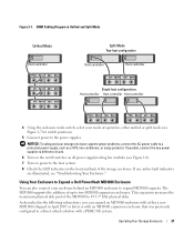
... EMMs are Installed 16 EMM Thermal Shutdown 17 Power Supply and Cooling Fan Features 17 Enclosure Alarms 18 2 Operating Your Storage Enclosure Before You Begin 19 Cabling Your Enclosure for Unified or Split Mode 19 Connecting the Enclosure 20 Using Your Enclosure to Expand a Dell PowerVault MD3000 Enclosure 21 Changing Your Enclosure's Operating Mode...
... EMMs are Installed 16 EMM Thermal Shutdown 17 Power Supply and Cooling Fan Features 17 Enclosure Alarms 18 2 Operating Your Storage Enclosure Before You Begin 19 Cabling Your Enclosure for Unified or Split Mode 19 Connecting the Enclosure 20 Using Your Enclosure to Expand a Dell PowerVault MD3000 Enclosure 21 Changing Your Enclosure's Operating Mode...
Hardware Owners Manual
Page 4
... Bay 36 Installing and Removing an EMM Module Cover 36 Removing and Installing the Power Supply/Cooling Fan Module 36 Removing a Power Supply/Cooling Fan Module 37 Installing a Power Supply/Cooling Fan Module 38 Removing and Installing the Control Panel 38 Removing the Control... 43 Troubleshooting External Connections 45 Troubleshooting a Wet Enclosure 45 Troubleshooting a Damaged Enclosure 46 Troubleshooting Power Supplies 46 Troubleshooting Enclosure Cooling Problems 47 Troubleshooting a Fan 48 Troubleshooting SAS and SATA Drives 48 Troubleshooting Enclosure Connections 49 4 ...
... Bay 36 Installing and Removing an EMM Module Cover 36 Removing and Installing the Power Supply/Cooling Fan Module 36 Removing a Power Supply/Cooling Fan Module 37 Installing a Power Supply/Cooling Fan Module 38 Removing and Installing the Control Panel 38 Removing the Control... 43 Troubleshooting External Connections 45 Troubleshooting a Wet Enclosure 45 Troubleshooting a Damaged Enclosure 46 Troubleshooting Power Supplies 46 Troubleshooting Enclosure Cooling Problems 47 Troubleshooting a Fan 48 Troubleshooting SAS and SATA Drives 48 Troubleshooting Enclosure Connections 49 4 ...
Hardware Owners Manual
Page 8
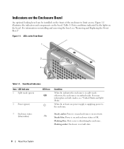
Figure 1-1. Front Bezel Indicators Item LED Indicator 1 Split mode (green) LED Icon 2 Power (green) Condition When lit, indicates the enclosure is in unified mode. LEDs on the bezel. For information on installing and removing the ...Enclosure is identifying the enclosure. Table 1-1 lists conditions indicated by the lights on the Front Bezel 1 2 3 Table 1-1. When lit, at least one power supply is supplying power to limit access. Figure 1-1 illustrates the indicators and components on the bezel. For more information on both modes, see "Removing and Replacing the Front ...
Figure 1-1. Front Bezel Indicators Item LED Indicator 1 Split mode (green) LED Icon 2 Power (green) Condition When lit, indicates the enclosure is in unified mode. LEDs on the bezel. For information on installing and removing the ...Enclosure is identifying the enclosure. Table 1-1 lists conditions indicated by the lights on the Front Bezel 1 2 3 Table 1-1. When lit, at least one power supply is supplying power to limit access. Figure 1-1 illustrates the indicators and components on the bezel. For more information on both modes, see "Removing and Replacing the Front ...
Hardware Owners Manual
Page 10
when set in its uppermost position at power on . The activity LED flashes whenever the drive is supplying power to power on , the enclosure is in split-mode configuration;... About Your System 2 status LED Table 1-2. Figure 1-3. Front-Panel Components (continued) Component Icon Condition Power LED (green) When lit, at power on enclosure configuration until the system is configured in your enclosure has two LEDs: an activity LED ...must be set in its lowermost position at least one power supply is accessed. Table 1-3 lists the flash patterns for the status LED.
when set in its uppermost position at power on . The activity LED flashes whenever the drive is supplying power to power on , the enclosure is in split-mode configuration;... About Your System 2 status LED Table 1-2. Figure 1-3. Front-Panel Components (continued) Component Icon Condition Power LED (green) When lit, at power on enclosure configuration until the system is configured in your enclosure has two LEDs: an activity LED ...must be set in its lowermost position at least one power supply is accessed. Table 1-3 lists the flash patterns for the status LED.

Hardware Owners Manual
Page 11
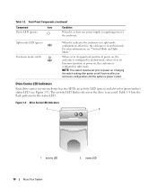
...Indicators and Features Figure 1-4 shows the back-panel features of enclosure) EMM bay. For more information, see "Power Supply and Cooling Fan Features." Both power supply/cooling fan modules must reside in the primary (left, as seen from rear of a fully populated enclosure containing ...both enclosure management modules (EMMs) and two power supply/cooling fan modules. The enclosure requires at least one power supply/cooling fan module. Table 1-3. Drive Carrier Status LEDs LED Description Off Slot empty, drive not yet ...
...Indicators and Features Figure 1-4 shows the back-panel features of enclosure) EMM bay. For more information, see "Power Supply and Cooling Fan Features." Both power supply/cooling fan modules must reside in the primary (left, as seen from rear of a fully populated enclosure containing ...both enclosure management modules (EMMs) and two power supply/cooling fan modules. The enclosure requires at least one power supply/cooling fan module. Table 1-3. Drive Carrier Status LEDs LED Description Off Slot empty, drive not yet ...
Hardware Owners Manual
Page 12
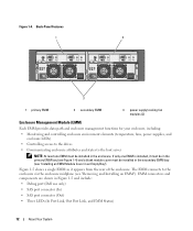
...EMM provides data path and enclosure management functions for your enclosure, including: • Monitoring and controlling enclosure environment elements (temperature, fans, power supplies, and enclosure LEDs) • Controlling access to the drives • Communicating enclosure attributes and states to the enclosure via the enclosure... midplane (see "Installing an EMM Module Cover in Figure 1-5 and include: • Debug port (Dell use only) • SAS port connector (In) • SAS port connector (Out) • Three LEDs (In Port Link, Out...
...EMM provides data path and enclosure management functions for your enclosure, including: • Monitoring and controlling enclosure environment elements (temperature, fans, power supplies, and enclosure LEDs) • Controlling access to the drives • Communicating enclosure attributes and states to the enclosure via the enclosure... midplane (see "Installing an EMM Module Cover in Figure 1-5 and include: • Debug port (Dell use only) • SAS port connector (In) • SAS port connector (Out) • Three LEDs (In Port Link, Out...
Hardware Owners Manual
Page 16
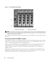
Changing the position of the switch while the enclosure is on power to another failover event. 16 About Your System Enclosure Failover When Two EMMs are Installed If two EMMs are installed, a certain degree of the enclosure ... change the enclosure mode, you must change the position of an EMM failure. For a complete description of the roles of the audible alarm, enclosure LEDs, power supplies, and fans.
Changing the position of the switch while the enclosure is on power to another failover event. 16 About Your System Enclosure Failover When Two EMMs are Installed If two EMMs are installed, a certain degree of the enclosure ... change the enclosure mode, you must change the position of an EMM failure. For a complete description of the roles of the audible alarm, enclosure LEDs, power supplies, and fans.
Hardware Owners Manual
Page 17
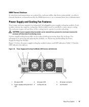
... /off switch About Your System 17 Figure 1-8. Power Supply and Cooling Fan Module LED Features and Indicators 1 2 3 4 5 1 DC power LED 3 2 Power supply/cooling fan fault 4 LED AC power LED cooling fans (2) 6 5 AC power connector 6 on enclosure; CAUTION: A power supply/cooling fan module can be removed from Server Administrator. Figure 1-8 shows the power supply/cooling fan module features and LED indicators. For...
... /off switch About Your System 17 Figure 1-8. Power Supply and Cooling Fan Module LED Features and Indicators 1 2 3 4 5 1 DC power LED 3 2 Power supply/cooling fan fault 4 LED AC power LED cooling fans (2) 6 5 AC power connector 6 on enclosure; CAUTION: A power supply/cooling fan module can be removed from Server Administrator. Figure 1-8 shows the power supply/cooling fan module features and LED indicators. For...

Hardware Owners Manual
Page 18
...10 seconds. NOTE: It is within specifications. On: DC output voltages are within specifications. For more fan blowers have failed or a power supply/cooling fan module is activated if any enclosure component. 18 About Your System Table 1-6. One cooling fan has failed. One EMM has... alarm is not installed. Off: No fault condition is disabled by default. Power Supply/Cooling Fan Module LED Indicators LED type DC power LED color Green Power Amber supply/cooling fan fault AC power Green LED Icon Function On: DC output voltages are not within specifications or ...
...10 seconds. NOTE: It is within specifications. On: DC output voltages are within specifications. For more fan blowers have failed or a power supply/cooling fan module is activated if any enclosure component. 18 About Your System Table 1-6. One cooling fan has failed. One EMM has... alarm is not installed. Off: No fault condition is disabled by default. Power Supply/Cooling Fan Module LED Indicators LED type DC power LED color Green Power Amber supply/cooling fan fault AC power Green LED Icon Function On: DC output voltages are not within specifications or ...
Hardware Owners Manual
Page 21
... two MD1000 expansion enclosures. This expansion increases the maximum physical disk pool of up to the power supplies. If any amber fault indicators are illuminated, see Figure 1-8). 7 Turn on power to the host system. 8 Check the LED indicators on all power supply/cooling fan modules (see "Troubleshooting Your Enclosure." If possible, connect the two power supplies to Expand a Dell PowerVault...
... two MD1000 expansion enclosures. This expansion increases the maximum physical disk pool of up to the power supplies. If any amber fault indicators are illuminated, see Figure 1-8). 7 Turn on power to the host system. 8 Check the LED indicators on all power supply/cooling fan modules (see "Troubleshooting Your Enclosure." If possible, connect the two power supplies to Expand a Dell PowerVault...
Hardware Owners Manual
Page 24
.... 2 When changing from unified mode to the MD3000 enclosure, as shown in the Dell PowerVault Compatibility Matrix (available from split mode to turn on . 6 Turn off both power supply/cooling fan modules. 8 Power on the server. 9 Re-create any attached hosts. Wait for the enclosure status LED... For more information, see Figure 1-7). 6 Rearrange the disks in the enclosure as necessary. 7 Power on the enclosure by turning off the MD3000 enclosure. 7 Connect the MD1000 expansion enclosure(s) to split mode, remove any virtual disk configurations that daisy chaining of enclosures is ...
.... 2 When changing from unified mode to the MD3000 enclosure, as shown in the Dell PowerVault Compatibility Matrix (available from split mode to turn on . 6 Turn off both power supply/cooling fan modules. 8 Power on the server. 9 Re-create any attached hosts. Wait for the enclosure status LED... For more information, see Figure 1-7). 6 Rearrange the disks in the enclosure as necessary. 7 Power on the enclosure by turning off the MD3000 enclosure. 7 Connect the MD1000 expansion enclosure(s) to split mode, remove any virtual disk configurations that daisy chaining of enclosures is ...
Hardware Owners Manual
Page 27
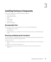
... to step 3. 2 Turn the key to the left to install the following components: • Front bezel (optional) • Drives and drive carriers • EMMs • Power supplies • Control panel • Enclosure midplane Recommended Tools The procedures in this section require the use of one or more of the following tools: •...
... to step 3. 2 Turn the key to the left to install the following components: • Front bezel (optional) • Drives and drive carriers • EMMs • Power supplies • Control panel • Enclosure midplane Recommended Tools The procedures in this section require the use of one or more of the following tools: •...
Hardware Owners Manual
Page 36
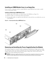
... module can operate temporarily with only one functional power supply, both cooling modules (with the edges of the EMM bay (see Figure 3-6). 2 Push the ...cover, pull out on the thin tabs on enclosure for a single EMM, the empty EMM bay must be removed from a powered-on each ) must contain a module cover to ensure proper airflow. Three of the four fans must be operational to prevent... of 5 minutes. Figure 3-6. Removing and Installing an EMM Module Cover Removing and Installing the Power Supply/Cooling Fan Module Your enclosure supports two separate modules containing an integrated...
... module can operate temporarily with only one functional power supply, both cooling modules (with the edges of the EMM bay (see Figure 3-6). 2 Push the ...cover, pull out on the thin tabs on enclosure for a single EMM, the empty EMM bay must be removed from a powered-on each ) must contain a module cover to ensure proper airflow. Three of the four fans must be operational to prevent... of 5 minutes. Figure 3-6. Removing and Installing an EMM Module Cover Removing and Installing the Power Supply/Cooling Fan Module Your enclosure supports two separate modules containing an integrated...
Hardware Owners Manual
Page 37
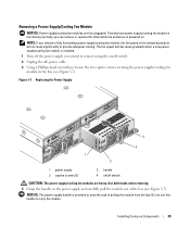
...the bay (see Figure 3-7). Use both hands when removing. 4 Grasp the handle on . Removing a Power Supply/Cooling Fan Module NOTICE: Power supply/cooling fan modules are heavy. Provided one power supply/cooling fan module is functioning normally, you intend to ease the task of the bay (see Figure 3-7).... Figure 3-7. NOTICE: The power-supply handle is installed. 1 Turn off switch CAUTION: The power supply/cooling fan modules are hot-pluggable. The fan speed will increase significantly to carry the module. Do...
...the bay (see Figure 3-7). Use both hands when removing. 4 Grasp the handle on . Removing a Power Supply/Cooling Fan Module NOTICE: Power supply/cooling fan modules are heavy. Provided one power supply/cooling fan module is functioning normally, you intend to ease the task of the bay (see Figure 3-7).... Figure 3-7. NOTICE: The power-supply handle is installed. 1 Turn off switch CAUTION: The power supply/cooling fan modules are hot-pluggable. The fan speed will increase significantly to carry the module. Do...
Hardware Owners Manual
Page 38
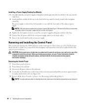
... the drives from the enclosure (see Figure 1-8) remain off switch. 3 Tighten the two captive screws to secure the new power supply/cooling fan module in the backplane connector. Before performing any of the components inside the enclosure and protecting against electrostatic discharge. ...Enclosure Mode Selection switch. Removing and Installing the Control Panel The control panel powers the LED indicators on the new power supply. Installing a Power Supply/Cooling Fan Module 1 Carefully slide the new power supply/cooling fan module approximately two-thirds of the way into the empty bay...
... the drives from the enclosure (see Figure 1-8) remain off switch. 3 Tighten the two captive screws to secure the new power supply/cooling fan module in the backplane connector. Before performing any of the components inside the enclosure and protecting against electrostatic discharge. ...Enclosure Mode Selection switch. Removing and Installing the Control Panel The control panel powers the LED indicators on the new power supply. Installing a Power Supply/Cooling Fan Module 1 Carefully slide the new power supply/cooling fan module approximately two-thirds of the way into the empty bay...
Hardware Owners Manual
Page 40
... are authorized to remove the enclosure cover and access any procedure, see your Product Information Guide for the drives, EMMs, control panel, and power supply/cooling modules. 1 Complete the "Removing the Control Panel" steps as shown in "Removing and Installing the Control Panel." 2 Remove the EMMs... from the enclosure. (See "Removing and Installing an EMM.") 3 Remove both power supply/cooling modules from the enclosure. (See "Removing and Installing the Power Supply/Cooling Fan Module.") 4 Remove the four Phillips screws holding the EMM...
... are authorized to remove the enclosure cover and access any procedure, see your Product Information Guide for the drives, EMMs, control panel, and power supply/cooling modules. 1 Complete the "Removing the Control Panel" steps as shown in "Removing and Installing the Control Panel." 2 Remove the EMMs... from the enclosure. (See "Removing and Installing an EMM.") 3 Remove both power supply/cooling modules from the enclosure. (See "Removing and Installing the Power Supply/Cooling Fan Module.") 4 Remove the four Phillips screws holding the EMM...
Hardware Owners Manual
Page 41
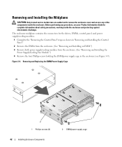
Removing and Installing the Midplane 1 1 midplane Installing Enclosure Components 43 5 Slide the EMM/power supply cage out of the enclosure and place it aside. 6 Reaching into the enclosure chassis from the back, carefully disconnect the midplane from the control panel and lift it out of the enclosure. (See Figure 3-10.) 7 To re-install the midplane, reverse the previous steps. Figure 3-10.
Removing and Installing the Midplane 1 1 midplane Installing Enclosure Components 43 5 Slide the EMM/power supply cage out of the enclosure and place it aside. 6 Reaching into the enclosure chassis from the back, carefully disconnect the midplane from the control panel and lift it out of the enclosure. (See Figure 3-10.) 7 To re-install the midplane, reverse the previous steps. Figure 3-10.
Hardware Owners Manual
Page 46
... • All drives (both in their carriers and connected to the electrical outlet and turn on the enclosure. 4 Remove the power supply/cooling fan modules from the enclosure. Troubleshooting a Damaged Enclosure Problem • Enclosure was dropped or damaged. Before performing any procedure, ... the enclosure cover and access any diagnostics available in the previous steps. 8 Reconnect the enclosure to the enclosure midplane) • Power supply/cooling fan modules • EMMs • Enclosure midplane 2 Ensure that there are properly connected and that all the components you removed...
... • All drives (both in their carriers and connected to the electrical outlet and turn on the enclosure. 4 Remove the power supply/cooling fan modules from the enclosure. Troubleshooting a Damaged Enclosure Problem • Enclosure was dropped or damaged. Before performing any procedure, ... the enclosure cover and access any diagnostics available in the previous steps. 8 Reconnect the enclosure to the enclosure midplane) • Power supply/cooling fan modules • EMMs • Enclosure midplane 2 Ensure that there are properly connected and that all the components you removed...
Hardware Owners Manual
Page 47
...against electrostatic discharge. If the AC Power LED is not lit, troubleshoot the power cord and power source into which the power supply is properly installed by removing and re-installing it is turned on a single functioning power supply; The enclosure can be removed from... minutes, the enclosure will overheat and may cause an automatic thermal shutdown. 3 Ensure that the power supply is plugged. • Use a known good power source (outlet). • Use a known good power cord. however, both modules must be installed to 5 minutes, provided the other module is obstructed...
...against electrostatic discharge. If the AC Power LED is not lit, troubleshoot the power cord and power source into which the power supply is properly installed by removing and re-installing it is turned on a single functioning power supply; The enclosure can be removed from... minutes, the enclosure will overheat and may cause an automatic thermal shutdown. 3 Ensure that the power supply is plugged. • Use a known good power source (outlet). • Use a known good power cord. however, both modules must be installed to 5 minutes, provided the other module is obstructed...


