
Glossary
Page 6
... local-bus implementation. Software written for processor. PXE - RAC - NVRAM - OID - parity stripe - In RAID arrays, a striped hard drive containing parity data. PowerEdge RAID controller. Pixels are arranged in a rack. Power-on another processor. processor - A way of pixels up and down. Object identifier is an extension of sources. You must usually be...
... local-bus implementation. Software written for processor. PXE - RAC - NVRAM - OID - parity stripe - In RAID arrays, a striped hard drive containing parity data. PowerEdge RAID controller. Pixels are arranged in a rack. Power-on another processor. processor - A way of pixels up and down. Object identifier is an extension of sources. You must usually be...

Information Update - Power Infrastructure Sizing
Page 1
... regulatory and safety guidance is used for infrastructure sizing. Using system power capping at 1000W and the characterization results in a rack, the total load can be used to adequately provision the facility. When deploying 20 of the same configuration in 500W of...less efficient and more accurately approximate the appropriate size of power consumption for a deployment. On-line capacity planning tools available from Dell system management software provide additional predictability for a specific deployment, the assessment may help to assess power consumption of the hardware. ...
... regulatory and safety guidance is used for infrastructure sizing. Using system power capping at 1000W and the characterization results in a rack, the total load can be used to adequately provision the facility. When deploying 20 of the same configuration in 500W of...less efficient and more accurately approximate the appropriate size of power consumption for a deployment. On-line capacity planning tools available from Dell system management software provide additional predictability for a specific deployment, the assessment may help to assess power consumption of the hardware. ...
Getting Started Guide
Page 5
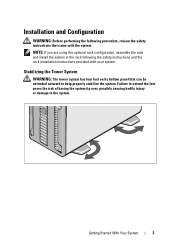
... over, possibly causing bodily injury or damage to help properly stabilize the system. NOTE: If you are using the optional rack configuration, assemble the rails and install the system in the rack following procedure, review the safety instructions that can be extended outward to the system. Installation and Configuration WARNING: Before performing...
... over, possibly causing bodily injury or damage to help properly stabilize the system. NOTE: If you are using the optional rack configuration, assemble the rails and install the system in the rack following procedure, review the safety instructions that can be extended outward to the system. Installation and Configuration WARNING: Before performing...

Getting Started Guide
Page 9
...tools for updates on supported operating systems, see www.dell.com. Warranty information may be included within this document or as a separate document. • The rack documentation included with your rack solution describes how to install your system into a rack. • The Hardware Owner's Manual provides information ... Version 4.0 (embedded) • Citrix® XenServer™ Enterprise edition 5.x (embedded) • Microsoft Hyper-V™ NOTE: For the latest information on support.dell.com and read the updates first because they often supersede information in other documents.
...tools for updates on supported operating systems, see www.dell.com. Warranty information may be included within this document or as a separate document. • The rack documentation included with your rack solution describes how to install your system into a rack. • The Hardware Owner's Manual provides information ... Version 4.0 (embedded) • Citrix® XenServer™ Enterprise edition 5.x (embedded) • Microsoft Hyper-V™ NOTE: For the latest information on support.dell.com and read the updates first because they often supersede information in other documents.

Hardware Owner's Manual
Page 21
..., the LCD panel on the front and the system status indicator on the front and back panels can be used to locate a particular system within a rack. If the system hangs during POST, press and hold the system ID button for more than 5 seconds to six PCI Express (generation 2) expansion cards. Slot...
..., the LCD panel on the front and the system status indicator on the front and back panels can be used to locate a particular system within a rack. If the system hangs during POST, press and hold the system ID button for more than 5 seconds to six PCI Express (generation 2) expansion cards. Slot...
Hardware Owner's Manual
Page 56
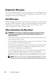
Alert messages include information, status, warning, and failure messages for updates on support.dell.com/manuals and read the updates first because they often supersede information in other documents. 56 About Your System Other Information You...on your system. Alert Messages Systems management software generates alert messages for configuring and managing your system, including those pertaining to install your system into a rack. • The Getting Started Guide provides an overview of system features, setting up your system, and technical specifications. • The Unified Server ...
Alert messages include information, status, warning, and failure messages for updates on support.dell.com/manuals and read the updates first because they often supersede information in other documents. 56 About Your System Other Information You...on your system. Alert Messages Systems management software generates alert messages for configuring and managing your system, including those pertaining to install your system into a rack. • The Getting Started Guide provides an overview of system features, setting up your system, and technical specifications. • The Unified Server ...

Hardware Owner's Manual
Page 79
... Components NOTE: The procedures and figures in this procedure, review the safety instructions that your system is in a tower configuration. If your system is in a rack configuration, disregard any of the components inside the system.
... Components NOTE: The procedures and figures in this procedure, review the safety instructions that your system is in a tower configuration. If your system is in a rack configuration, disregard any of the components inside the system.

Hardware Owner's Manual
Page 82
... and Installing a Power Supply 1 1 power-supply handle 3 release latch 2 3 2 Velcro strap 82 Installing System Components For information about the cable management arm, see the system's rack documentation. 1 Disconnect the power cable from the power source and the power supply you intend to unlatch and lift the optional cable management arm if...
... and Installing a Power Supply 1 1 power-supply handle 3 release latch 2 3 2 Velcro strap 82 Installing System Components For information about the cable management arm, see the system's rack documentation. 1 Disconnect the power cable from the power source and the power supply you intend to unlatch and lift the optional cable management arm if...

Hardware Owner's Manual
Page 83
... cable, secure the cable with the power supply bay and insert it into the chassis until the power supply is functioning properly (see the system's rack documentation. 2 Connect the power cable to the power supply and plug the cable into place. The power supply status indicator will turn green to recognize...
... cable, secure the cable with the power supply bay and insert it into the chassis until the power supply is functioning properly (see the system's rack documentation. 2 Connect the power cable to the power supply and plug the cable into place. The power supply status indicator will turn green to recognize...
Hardware Owner's Manual
Page 200
... run on another processor. Storage Area Network. An internal or external device, such as the number of pixels across by the number of code in a rack. A single point on motherboard. POST - The primary computational chip inside the system that initiates your system, the POST tests various system components such as RAM...
... run on another processor. Storage Area Network. An internal or external device, such as the number of pixels across by the number of code in a rack. A single point on motherboard. POST - The primary computational chip inside the system that initiates your system, the POST tests various system components such as RAM...

Tower-to-Rack Conversion Guide
Page 1
Dell™ PowerEdge™ T710 Systems Tower-to-Rack Conversion Guide
Dell™ PowerEdge™ T710 Systems Tower-to-Rack Conversion Guide
Tower-to-Rack Conversion Guide
Page 3
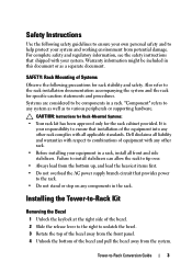
... the AC power supply branch circuit that provides power to the rack. • Do not stand or step on any system as well as a separate document. Also refer to the rack installation documentation accompanying the system and the rack for the rack cabinet provided. Dell disclaims all liability and warranties with your system and working...
... the AC power supply branch circuit that provides power to the rack. • Do not stand or step on any system as well as a separate document. Also refer to the rack installation documentation accompanying the system and the rack for the rack cabinet provided. Dell disclaims all liability and warranties with your system and working...
Tower-to-Rack Conversion Guide
Page 4
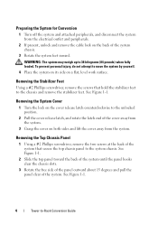
... outward about 15 degrees and pull the panel clear of the system chassis. 3 Rotate the system feet inward. WARNING: The system may weigh up to -Rack Conversion Guide See Figure 1-1. To prevent personal injury, do not attempt to the system chassis. Removing the Stabilizer Feet Using a #2 Phillips screwdriver, remove the screws...
... outward about 15 degrees and pull the panel clear of the system chassis. 3 Rotate the system feet inward. WARNING: The system may weigh up to -Rack Conversion Guide See Figure 1-1. To prevent personal injury, do not attempt to the system chassis. Removing the Stabilizer Feet Using a #2 Phillips screwdriver, remove the screws...
Tower-to-Rack Conversion Guide
Page 5
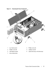
Removing the Tower Components 1 2 7 6 5 1 top chassis panel 3 Phillips screw (4) 5 LCD display module 7 drive release latch 4 3 2 Phillips screw (2) 4 stabilizer foot (4) 6 optical drive (top or left drive bay) Tower-to-Rack Conversion Guide 5 Figure 1-1.
Removing the Tower Components 1 2 7 6 5 1 top chassis panel 3 Phillips screw (4) 5 LCD display module 7 drive release latch 4 3 2 Phillips screw (2) 4 stabilizer foot (4) 6 optical drive (top or left drive bay) Tower-to-Rack Conversion Guide 5 Figure 1-1.

Tower-to-Rack Conversion Guide
Page 6
...the drive out to remove it from the drive bay. 2 Rotate the LCD display module 90 degrees clockwise to the back of the arrow to -Rack Conversion Guide b Slide the drive release latch in the system. a Align the shoulder screws on the optical drive with the screw holes on the ...the bezel. 6 Tower-to release the drive. Rotating the LCD Display Module 1 Remove the optical drive from the top (or left rack ear piece. Installing the Rack Ears 1 Align the rack ear screw holes with the drive bay screw slots. See Figure 1-1. Installing the Bezel 1 Insert the tabs at the bottom of ...
...the drive out to remove it from the drive bay. 2 Rotate the LCD display module 90 degrees clockwise to the back of the arrow to -Rack Conversion Guide b Slide the drive release latch in the system. a Align the shoulder screws on the optical drive with the screw holes on the ...the bezel. 6 Tower-to release the drive. Rotating the LCD Display Module 1 Remove the optical drive from the top (or left rack ear piece. Installing the Rack Ears 1 Align the rack ear screw holes with the drive bay screw slots. See Figure 1-1. Installing the Bezel 1 Insert the tabs at the bottom of ...
Tower-to-Rack Conversion Guide
Page 7
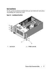
Figure 1-2. Installing the Rack Ears 1 rack ear (2) 1 2 2 Phillips screw (6) Tower-to-Rack Conversion Guide 7 Rack Installation See the rack documentation included with your rack solution for instructions on installing your system into a rack.
Figure 1-2. Installing the Rack Ears 1 rack ear (2) 1 2 2 Phillips screw (6) Tower-to-Rack Conversion Guide 7 Rack Installation See the rack documentation included with your rack solution for instructions on installing your system into a rack.


