Glossary
Page 9
... the number of pixels up and down. The ability via software to host multiple operating systems. W - A single physical system may be integrated into an expansion slot. WH - VGA and SVGA are video standards for example. video adapter - Zero insertion force. 9 A program used to your monitor must install the appropriate video drivers...
... the number of pixels up and down. The ability via software to host multiple operating systems. W - A single physical system may be integrated into an expansion slot. WH - VGA and SVGA are video standards for example. video adapter - Zero insertion force. 9 A program used to your monitor must install the appropriate video drivers...

Installing the Optional Casters on your System
Page 1
... foot. 6 Carefully place the system upright and on its side on your System The optional casters for property damage, personal injury, or death. A00 DELL CONFIDENTIAL - See Figure 1. c Secure the foot to assist you. FOR PROOF ONLY WARNING: Whenever you need to lift the system, get others to... screw per foot), which attach to the bottom of the system. b Rotate the foot towards the system, inserting the back metal tab into the tab slots in Figure 1. 4 Remove the four system feet by yourself. 3 Lay the system on its feet on a flat, stable surface. 7 Reattach any attached ...
... foot. 6 Carefully place the system upright and on its side on your System The optional casters for property damage, personal injury, or death. A00 DELL CONFIDENTIAL - See Figure 1. c Secure the foot to assist you. FOR PROOF ONLY WARNING: Whenever you need to lift the system, get others to... screw per foot), which attach to the bottom of the system. b Rotate the foot towards the system, inserting the back metal tab into the tab slots in Figure 1. 4 Remove the four system feet by yourself. 3 Lay the system on its feet on a flat, stable surface. 7 Reattach any attached ...

Installing the Optional Casters on your System
Page 2
... 3 4 2 1 5 6 1 tab slot (6) 3 back metal tab (1 per foot) 5 captive screw (1 per foot) 2 front metal tab (2 per foot) 4 caster (4) 6 stabilizer foot (2) Information in this document to refer to change without the written permission of Dell Inc. is subject to either the entities claiming... interest in the U.S.A. disclaims any manner whatsoever without notice. © 2008 Dell Inc. Reproduction of Dell Inc. All rights reserved. Trademarks used in this text: Dell and the DELL logo are trademarks of these materials in this document is strictly forbidden. FOR ...
... 3 4 2 1 5 6 1 tab slot (6) 3 back metal tab (1 per foot) 5 captive screw (1 per foot) 2 front metal tab (2 per foot) 4 caster (4) 6 stabilizer foot (2) Information in this document to refer to change without the written permission of Dell Inc. is subject to either the entities claiming... interest in the U.S.A. disclaims any manner whatsoever without notice. © 2008 Dell Inc. Reproduction of Dell Inc. All rights reserved. Trademarks used in this text: Dell and the DELL logo are trademarks of these materials in this document is strictly forbidden. FOR ...

Information Update
Page 1
...than its own. Trademarks used in the Hardware Owner's Manual at support.dell.com/manuals. June 2009 Reproduction of Dell Inc. is subject to change without the written permission of Dell Inc. To locate expansion-card slots on your system board, see "System Board Connectors" in this document .... Other trademarks and trade names may be used in this text: Dell and the DELL logo are trademarks of these materials in any proprietary interest in this document to refer to Expansion Card Slot The expansion-card slot 1 on the system board supports a half-length PCIe x8 card ...
...than its own. Trademarks used in the Hardware Owner's Manual at support.dell.com/manuals. June 2009 Reproduction of Dell Inc. is subject to change without the written permission of Dell Inc. To locate expansion-card slots on your system board, see "System Board Connectors" in this document .... Other trademarks and trade names may be used in this text: Dell and the DELL logo are trademarks of these materials in any proprietary interest in this document to refer to Expansion Card Slot The expansion-card slot 1 on the system board supports a half-length PCIe x8 card ...
Getting Started Guide
Page 10
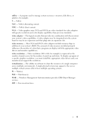
... this guide or if the system does not perform as expected, see your Hardware Owner's Manual. All slots support up to add-in . 800-Mhz, 1066-MHz, or 1333-MHz DDR3 registered or unbuffered Error...dell.com/training for more information. Technical Specifications Processor Processor type Intel® Xeon® Processor 5500 series Expansion Bus Bus type Expansion slots Memory Architecture Memory module sockets Memory module capacities Minimum RAM Maximum RAM PCI Express Generation 2 Slot 0: PCIe x8 Storage Slot 1: PCIe x4 Slot 2: PCIe x16 Slot 3: PCIe x8 Slot 4: PCIe x8 Slot 5: PCIe x8 Slot...
... this guide or if the system does not perform as expected, see your Hardware Owner's Manual. All slots support up to add-in . 800-Mhz, 1066-MHz, or 1333-MHz DDR3 registered or unbuffered Error...dell.com/training for more information. Technical Specifications Processor Processor type Intel® Xeon® Processor 5500 series Expansion Bus Bus type Expansion slots Memory Architecture Memory module sockets Memory module capacities Minimum RAM Maximum RAM PCI Express Generation 2 Slot 0: PCIe x8 Storage Slot 1: PCIe x4 Slot 2: PCIe x16 Slot 3: PCIe x8 Slot 4: PCIe x8 Slot 5: PCIe x8 Slot...

Getting Started Guide
Page 11
... NICs) 9-pin, DTE, 16550-compatible Six 4-pin, USB 2.0-compliant 15-pin VGA Two 4-pin, USB 2.0-compliant One 4-pin, USB 2.0-compliant One optional flash memory card slot on internal SD module Getting Started With Your System 9
... NICs) 9-pin, DTE, 16550-compatible Six 4-pin, USB 2.0-compliant 15-pin VGA Two 4-pin, USB 2.0-compliant One 4-pin, USB 2.0-compliant One optional flash memory card slot on internal SD module Getting Started With Your System 9

Hardware Owner's Manual
Page 21
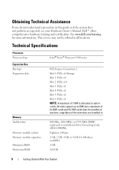
...particular system within a rack. Supports one full-height, full-length (30.99-cm [12.2-in]), x16 wide card in slots 2. Slot 6: PCIe x8 (x8 routing, Gen 2), half-length. 1100-W power supply. Supports one full-height, half-length, x4 wide card in... slots 4, 5, and 6. Slot 4: PCIe x8 (x8 routing, Gen 2), half-length. Item Indicator, Button, or Icon Connector 1 PCIe expansion card slots (6) 2 power supply 2 (PS2) 3 system identification button Description Connects up to enter BIOS Progress...
...particular system within a rack. Supports one full-height, full-length (30.99-cm [12.2-in]), x16 wide card in slots 2. Slot 6: PCIe x8 (x8 routing, Gen 2), half-length. 1100-W power supply. Supports one full-height, half-length, x4 wide card in... slots 4, 5, and 6. Slot 4: PCIe x8 (x8 routing, Gen 2), half-length. Item Indicator, Button, or Icon Connector 1 PCIe expansion card slots (6) 2 power supply 2 (PS2) 3 system identification button Description Connects up to enter BIOS Progress...
Hardware Owner's Manual
Page 22
... a VGA display to the system. 7 serial connector Connects a serial device to the system. Connects USB devices to the system. 8 iDRAC6 Enterprise port (optional) 9 VFlash media slot (optional) 10 USB connectors (6) 11 security cable slot Dedicated management port for the optional iDRAC6 Enterprise card. Turn on page 57. 22 About Your System
... a VGA display to the system. 7 serial connector Connects a serial device to the system. Connects USB devices to the system. 8 iDRAC6 Enterprise port (optional) 9 VFlash media slot (optional) 10 USB connectors (6) 11 security cable slot Dedicated management port for the optional iDRAC6 Enterprise card. Turn on page 57. 22 About Your System

Hardware Owner's Manual
Page 31
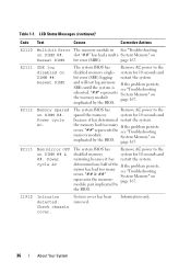
...AC power to the system origin. If error on a component that the problem persists, see resides in the specified "Troubleshooting slot. E171F PCIe fatal error on ##, device ##, function page 178. ##. LCD Status Messages (continued) Code Text Causes Corrective Actions E1711 PCI... parity error on Slot #. PCI parity error on Bus ## Device ## Function ## The system BIOS has Remove and reseat the reported a PCI parity error PCIe...
...AC power to the system origin. If error on a component that the problem persists, see resides in the specified "Troubleshooting slot. E171F PCIe fatal error on ##, device ##, function page 178. ##. LCD Status Messages (continued) Code Text Causes Corrective Actions E1711 PCI... parity error on Slot #. PCI parity error on Bus ## Device ## Function ## The system BIOS has Remove and reseat the reported a PCI parity error PCIe...
Hardware Owner's Manual
Page 36
... persists, mirror has had too many see "Troubleshooting rebooted. E2113 Mem mirror OFF on represents the memory- I1910 Intrusion detected. "## & ##" System Memory" on DIMM ## & ##. Table 1-1. slot "##" has had a multi- System Memory" on DIMM ##. LCD Status Messages (continued) Code Text Causes Corrective Actions E2110 Multibit Error The memory module in See "Troubleshooting...
... persists, mirror has had too many see "Troubleshooting rebooted. E2113 Mem mirror OFF on represents the memory- I1910 Intrusion detected. "## & ##" System Memory" on DIMM ## & ##. Table 1-1. slot "##" has had a multi- System Memory" on DIMM ##. LCD Status Messages (continued) Code Text Causes Corrective Actions E2110 Multibit Error The memory module in See "Troubleshooting...
Hardware Owner's Manual
Page 42
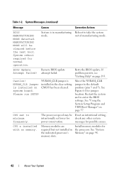
... may be cleared before the next boot. Install memory modules for jumper location. See Figure 6-1 for the processor. System is in the indicated processor's memory slots. CPU set lower for possible causes. See "System Memory" on system board. BIOS Update Remote BIOS update Attempt Failed! attempt failed. Restart the system and...
... may be cleared before the next boot. Install memory modules for jumper location. See Figure 6-1 for the processor. System is in the indicated processor's memory slots. CPU set lower for possible causes. See "System Memory" on system board. BIOS Update Remote BIOS update Attempt Failed! attempt failed. Restart the system and...

Hardware Owner's Manual
Page 44
... 8602 Auxiliary Device Failure. Embedded NICx and The OS NIC interface is installed in BIOS. Ensure that mouse and keyboard are installed in the Internal_Storage slot! See Management "Troubleshooting a NIC" on Shared NIC= page 161. The system halted because an invalid PCIe expansion card is set Check the system NICy: in...
... 8602 Auxiliary Device Failure. Embedded NICx and The OS NIC interface is installed in BIOS. Ensure that mouse and keyboard are installed in the Internal_Storage slot! See Management "Troubleshooting a NIC" on Shared NIC= page 161. The system halted because an invalid PCIe expansion card is set Check the system NICy: in...

Hardware Owner's Manual
Page 47
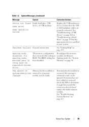
...hard-drive subsystem, or no operating system on page 193. No boot sector on Incorrect configuration hard drive settings in the specified specified slot number. If necessary, install the operating system on page 193. See "Getting Help" on your operating system documentation. PCIe Training Faulty...the PCIe card in the Error: Expected PCIe card in System Setup program, or no bootable USB key installed. If the is x, slot. Check the hard-drive configuration settings in the System Setup program. No timer tick interrupt Faulty system board. Use a bootable USB key...
...hard-drive subsystem, or no operating system on page 193. No boot sector on Incorrect configuration hard drive settings in the specified specified slot number. If necessary, install the operating system on page 193. See "Getting Help" on your operating system documentation. PCIe Training Faulty...the PCIe card in the Error: Expected PCIe card in System Setup program, or no bootable USB key installed. If the is x, slot. Check the hard-drive configuration settings in the System Setup program. No timer tick interrupt Faulty system board. Use a bootable USB key...
Hardware Owner's Manual
Page 49
... System 49 Seek operation failed Replace the USB medium or device. See "Getting Help" on page 167. The amount of three must be populated across slots. See "Troubleshooting System Memory" on page 193. System Messages (continued) Message Causes Corrective Actions Sector not found Faulty hard drive, USB Seek error device, or...
... System 49 Seek operation failed Replace the USB medium or device. See "Getting Help" on page 167. The amount of three must be populated across slots. See "Troubleshooting System Memory" on page 193. System Messages (continued) Message Causes Corrective Actions Sector not found Faulty hard drive, USB Seek error device, or...
Hardware Owner's Manual
Page 50
... "System Battery" on x thermal sensor is installed in rank count: x,x,... The following DIMMs should match in size and rank count: x,x,... See "System the specified memory slot. See "General Memory Module Installation Guidelines" on page 165. See "Troubleshooting the System Battery" on page 98. The following DIMMs should match in geometry: x,x,... If...
... "System Battery" on x thermal sensor is installed in rank count: x,x,... The following DIMMs should match in size and rank count: x,x,... See "System the specified memory slot. See "General Memory Module Installation Guidelines" on page 165. See "Troubleshooting the System Battery" on page 98. The following DIMMs should match in geometry: x,x,... If...

Hardware Owner's Manual
Page 53
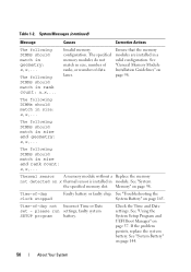
... memory configuration is Reconfigure the memory for mirroring or Memory Mirroring or installed in the Mode, or change the slot(s) are not specified slots are unused. DIMMs not optimal for detected. Modules in the Advanced ECC Memory Advanced ECC Memory following Mode.... the SEL. reboot. section in "Troubleshooting Your System" on page 98. See "System Memory" on page 98. DIMM mismatch across slots detected: x,x,... Invalid memory configuration. memory mode to information that the memory modules are mismatched in a valid configuration. See "System ECC mode...
... memory configuration is Reconfigure the memory for mirroring or Memory Mirroring or installed in the Mode, or change the slot(s) are not specified slots are unused. DIMMs not optimal for detected. Modules in the Advanced ECC Memory Advanced ECC Memory following Mode.... the SEL. reboot. section in "Troubleshooting Your System" on page 98. See "System Memory" on page 98. DIMM mismatch across slots detected: x,x,... Invalid memory configuration. memory mode to information that the memory modules are mismatched in a valid configuration. See "System ECC mode...

Hardware Owner's Manual
Page 81
... supply bay. NOTE: The power supply label specifies the maximum power output. See "Installing a Power Supply Blank" on page 83. 1 system cover 3 PCIe expansion card slots (6) 5 heat sink blank (single-processor configuration) 7 system feet (4) 9 SAS or SATA hard drives (up to 8 [3.5"] and 16 [2.5"]) 11 tape drive (optional) 13 internal SD module...
... supply bay. NOTE: The power supply label specifies the maximum power output. See "Installing a Power Supply Blank" on page 83. 1 system cover 3 PCIe expansion card slots (6) 5 heat sink blank (single-processor configuration) 7 system feet (4) 9 SAS or SATA hard drives (up to 8 [3.5"] and 16 [2.5"]) 11 tape drive (optional) 13 internal SD module...

Hardware Owner's Manual
Page 84
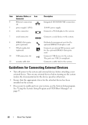
... arrow and rotate the top end of the front bezel. Removing and Installing the Front Bezel 3 2 1 1 front bezel 3 release latch 4 2 front bezel lock 4 bezel tab slots (2) 84 Installing System Components If you are removing or installing any other system component(s), the system should be turned off and placed in the orientation...
... arrow and rotate the top end of the front bezel. Removing and Installing the Front Bezel 3 2 1 1 front bezel 3 release latch 4 2 front bezel lock 4 bezel tab slots (2) 84 Installing System Components If you are removing or installing any other system component(s), the system should be turned off and placed in the orientation...
Hardware Owner's Manual
Page 85
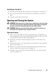
... the cover release latch and rotate the latch towards the back of the bezel into the chassis until the lever locks into the bezel tab slots in the chassis. See Figure 3-4. 5 Grasp the cover on the cover release latch counterclockwise to the unlocked position. See Figure 3-4. To avoid injury, do not...
... the cover release latch and rotate the latch towards the back of the bezel into the chassis until the lever locks into the bezel tab slots in the chassis. See Figure 3-4. 5 Grasp the cover on the cover release latch counterclockwise to the unlocked position. See Figure 3-4. To avoid injury, do not...

Hardware Owner's Manual
Page 86
... are connected and folded out of the way. 2 Ensure that no tools or extra parts are left inside the system. 3 Align the cover with the slots in chassis and lower the cover into place. 5 Turn the lock on a flat, stable surface. 7 Rotate the system feet outward. 86 Installing System Components See...
... are connected and folded out of the way. 2 Ensure that no tools or extra parts are left inside the system. 3 Align the cover with the slots in chassis and lower the cover into place. 5 Turn the lock on a flat, stable surface. 7 Rotate the system feet outward. 86 Installing System Components See...

