

Glossary
Page 5
...as a hexadecimal number, in memory modules (DIMMs). See also striping and RAID. Millimeter(s). NAS systems have their own operating systems, integrated hardware, and software that contains the CIM schema definition. Network interface controller. MAC address - Milliampere-hour(s). management station - MB - Megabits per ... additional drives stores duplicate copies of the concepts used to hard-drive capacity, the term is monitored and managed using Dell OpenManage™ Server Administrator. A specific location, usually expressed as integrated memory (ROM and RAM) and add-in...
...as a hexadecimal number, in memory modules (DIMMs). See also striping and RAID. Millimeter(s). NAS systems have their own operating systems, integrated hardware, and software that contains the CIM schema definition. Network interface controller. MAC address - Milliampere-hour(s). management station - MB - Megabits per ... additional drives stores duplicate copies of the concepts used to hard-drive capacity, the term is monitored and managed using Dell OpenManage™ Server Administrator. A specific location, usually expressed as integrated memory (ROM and RAM) and add-in...

Glossary
Page 6
... create an image. Peripheral Component Interconnect. A power source with multiple power outlets that communicates with the fdisk command. PowerEdge RAID controller. An internal or external device, such as RAM and hard drives. pixel - Before the operating system loads when ...You can contain multiple logical drives. Power distribution unit. A single point on self-test. Nonmaskable interrupt. OID - Redundant information that controls the interpretation and execution of data. You must usually be revised to run on your system. PDU - peripheral - POST - PXE...
... create an image. Peripheral Component Interconnect. A power source with multiple power outlets that communicates with the fdisk command. PowerEdge RAID controller. An internal or external device, such as RAM and hard drives. pixel - Before the operating system loads when ...You can contain multiple logical drives. Power distribution unit. A single point on self-test. Nonmaskable interrupt. OID - Redundant information that controls the interpretation and execution of data. You must usually be revised to run on your system. PDU - peripheral - POST - PXE...

Glossary
Page 8
... a crossover cable. A USB connector provides a single connection point for multiple USB-compliant devices, such as the processor(s), RAM, controllers for operation. Disk striping writes data across three or more processors connected via a high-bandwidth link and managed by changing settings in...several stripes on a network hub or switch used . termination - TOE - USB - Universal Serial Bus. See also guarding, mirroring, and RAID. Data stored in memory that has two or more disks in the cable. Uninterruptible power supply. Some devices (such as password protection. ...
... a crossover cable. A USB connector provides a single connection point for multiple USB-compliant devices, such as the processor(s), RAM, controllers for operation. Disk striping writes data across three or more processors connected via a high-bandwidth link and managed by changing settings in...several stripes on a network hub or switch used . termination - TOE - USB - Universal Serial Bus. See also guarding, mirroring, and RAID. Data stored in memory that has two or more disks in the cable. Uninterruptible power supply. Some devices (such as password protection. ...
Glossary
Page 46
... - Nonvolatile random access memory NVRAM OID - Master boot record MHz - Power distribution unit PDU PERC - Megabyte 1 MB = 1,048,576 1 MB = 1,000,000 Mbps - PowerEdge RAID 46 MAC Media Access Control mAh - Managed Object Format CIM ASCII ms - Object Identifier PCI - Megahertz mm - Nonmaskable interrupt NMI ns - Milliampere-hour Mb - Millimeter MOF - Millisecond NAS -
... - Nonvolatile random access memory NVRAM OID - Master boot record MHz - Power distribution unit PDU PERC - Megabyte 1 MB = 1,048,576 1 MB = 1,000,000 Mbps - PowerEdge RAID 46 MAC Media Access Control mAh - Managed Object Format CIM ASCII ms - Object Identifier PCI - Megahertz mm - Nonmaskable interrupt NMI ns - Milliampere-hour Mb - Millimeter MOF - Millisecond NAS -
Glossary
Page 47
... dynamic random-access memory sec - Storage Area Network SAS - Redundant array of independent disks RAID には、RAID 0、RAID 1、RAID 5、 RAID 10 RAID 50 RAM - Read-only memory ROM ROM ROM POST ROMB - Remote access controller RAID - POST - Power-on motherboard RAID)。 SAN - Preboot eXecution Environment LAN R-DIMM DDR3 RAC - Serial Advanced Technology...
... dynamic random-access memory sec - Storage Area Network SAS - Redundant array of independent disks RAID には、RAID 0、RAID 1、RAID 5、 RAID 10 RAID 50 RAM - Read-only memory ROM ROM ROM POST ROMB - Remote access controller RAID - POST - Power-on motherboard RAID)。 SAN - Preboot eXecution Environment LAN R-DIMM DDR3 RAC - Serial Advanced Technology...
Glossary
Page 56
...; CIM ASCII ms Millisecond NAS Network Attached Storage NAS NAS NIC Network Interface Controller NMI Nonmaskable Interrupt NMI ns Nanosecond NVRAM Nonvolatile Random-Access Memory NVRAM OID Object Identifier PCI Peripheral Component Interconnect PDU Power Distribution Unit PERC - PowerEdge RAID POST Power-On Self-Test POST RAM PXE Preboot eXecution Environment LAN R-DIMM...
...; CIM ASCII ms Millisecond NAS Network Attached Storage NAS NAS NIC Network Interface Controller NMI Nonmaskable Interrupt NMI ns Nanosecond NVRAM Nonvolatile Random-Access Memory NVRAM OID Object Identifier PCI Peripheral Component Interconnect PDU Power Distribution Unit PERC - PowerEdge RAID POST Power-On Self-Test POST RAM PXE Preboot eXecution Environment LAN R-DIMM...
Glossary
Page 57
... Analysis and Reporting Technology BIOS SMP Symmetric Multiprocessing 2 I /O SD 카드 - RAC Remote Access Controller RAID Redundant Array of Independent Disk RAID RAID 0, RAID 1, RAID 5, RAID 10 및 RAID 50 RAM Random-Access Memory RAM ROM Read-Only Memory ROM ROM ROM POST ROMB RAID(RAID On Motherboard SAN Storage Area Network SAS SCSI(Serial-Attached SCSI SATA Serial Advanced...
... Analysis and Reporting Technology BIOS SMP Symmetric Multiprocessing 2 I /O SD 카드 - RAC Remote Access Controller RAID Redundant Array of Independent Disk RAID RAID 0, RAID 1, RAID 5, RAID 10 및 RAID 50 RAM Random-Access Memory RAM ROM Read-Only Memory ROM ROM ROM POST ROMB RAID(RAID On Motherboard SAN Storage Area Network SAS SCSI(Serial-Attached SCSI SATA Serial Advanced...
Dell PowerEdge Deployment Guide
Page 4
... tips on the partition. The controller includes 1 GB of the more information, see the Microsoft Knowledge Base article 896536 on www.support.dell.com. This document will be assigned drive letter F:. Failing to do so can result in addition to Dell PowerEdge servers. Select the new partition ...during operating system deployment. USC allows you just created. 3. NOTE: This same behavior may see Best Practices for your operating system, RAID, and to the hard drive partition: 1. Create the partition again. These changes were needed to allow an existing deployment setup to ...
... tips on the partition. The controller includes 1 GB of the more information, see the Microsoft Knowledge Base article 896536 on www.support.dell.com. This document will be assigned drive letter F:. Failing to do so can result in addition to Dell PowerEdge servers. Select the new partition ...during operating system deployment. USC allows you just created. 3. NOTE: This same behavior may see Best Practices for your operating system, RAID, and to the hard drive partition: 1. Create the partition again. These changes were needed to allow an existing deployment setup to ...
Hardware Owner's Manual
Page 7
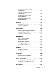
Removing an Integrated Storage Controller Card 112 Installing an Integrated Storage Controller Card 114 Removing the Expansion Card Stabilizer Bracket 115 Installing the Expansion Card Stabilizer Bracket 116 RAID Battery 117 Removing a RAID Battery 117 Installing a RAID Battery 118 Expansion Cards 118 Expansion Card Installation ...131 Removing a Processor 131 Installing a Processor 134 System Battery 136 Replacing the System Battery 136 Control Panel Assembly 138 Removing the Control Panel Assembly 138 Installing the Control Panel Assembly 141 SAS Backplane 142 Contents 7
Removing an Integrated Storage Controller Card 112 Installing an Integrated Storage Controller Card 114 Removing the Expansion Card Stabilizer Bracket 115 Installing the Expansion Card Stabilizer Bracket 116 RAID Battery 117 Removing a RAID Battery 117 Installing a RAID Battery 118 Expansion Cards 118 Expansion Card Installation ...131 Removing a Processor 131 Installing a Processor 134 System Battery 136 Replacing the System Battery 136 Control Panel Assembly 138 Removing the Control Panel Assembly 138 Installing the Control Panel Assembly 141 SAS Backplane 142 Contents 7
Hardware Owner's Manual
Page 26
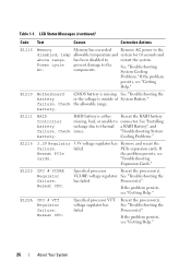
...Getting Help." Specified processor Reseat the processor(s). Specified processor VTT voltage regulator has failed. has been disabled to thermal a RAID Battery", and failure. E1216 3.3V Regulator 3.3V voltage regulator has Remove and reseat the failure. Table 1-1. See "... System battery. E1210 Motherboard CMOS battery is missing See "Troubleshooting the battery or the voltage is either Reseat the RAID battery Controller missing, bad, or unable to the components. "Troubleshooting Expansion Cards." E122A CPU # VTT Regulator failure. LCD ...
...Getting Help." Specified processor Reseat the processor(s). Specified processor VTT voltage regulator has failed. has been disabled to thermal a RAID Battery", and failure. E1216 3.3V Regulator 3.3V voltage regulator has Remove and reseat the failure. Table 1-1. See "... System battery. E1210 Motherboard CMOS battery is missing See "Troubleshooting the battery or the voltage is either Reseat the RAID battery Controller missing, bad, or unable to the components. "Troubleshooting Expansion Cards." E122A CPU # VTT Regulator failure. LCD ...
Hardware Owner's Manual
Page 37
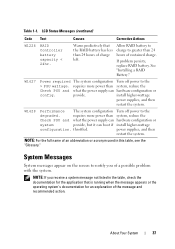
...supplies, and then restart the system. NOTE: If you of the message and recommended action. If problem persists, replace RAID battery. See "Installing a RAID Battery." requires more power than system, reduce the Check PSU and what the power supply can boot if install higher...system provide, but it can hardware configuration or config. LCD Status Messages (continued) Code Text Causes Corrective Actions W1228 RAID Controller battery capacity < 24hr. provide. Allow RAID battery to charge to notify you receive a system message not listed in this table, see the "Glossary." NOTE...
...supplies, and then restart the system. NOTE: If you of the message and recommended action. If problem persists, replace RAID battery. See "Installing a RAID Battery." requires more power than system, reduce the Check PSU and what the power supply can boot if install higher...system provide, but it can hardware configuration or config. LCD Status Messages (continued) Code Text Causes Corrective Actions W1228 RAID Controller battery capacity < 24hr. provide. Allow RAID battery to charge to notify you receive a system message not listed in this table, see the "Glossary." NOTE...
Hardware Owner's Manual
Page 64
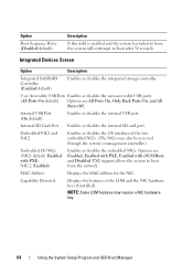
... the system will reattempt to boot from the network. Integrated Devices Screen Option Description Integrated SAS/RAID Controller (Enabled default) Enables or disables the integrated storage controller. Embedded NIC1 and NIC2 Enables or disables the OS interface of the LOM and the NIC ... are Enabled, Enabled with PXE, Enabled with PXE; NOTE: Some LOM features may also be accessed through the system's management controller.) Embedded Gb NICx (NIC1 default: Enabled with iSCSI Boot, and Disabled. Capability Detected Displays the features of the two embedded NICs...
... the system will reattempt to boot from the network. Integrated Devices Screen Option Description Integrated SAS/RAID Controller (Enabled default) Enables or disables the integrated storage controller. Embedded NIC1 and NIC2 Enables or disables the OS interface of the LOM and the NIC ... are Enabled, Enabled with PXE, Enabled with PXE; NOTE: Some LOM features may also be accessed through the system's management controller.) Embedded Gb NICx (NIC1 default: Enabled with iSCSI Boot, and Disabled. Capability Detected Displays the features of the two embedded NICs...
Hardware Owner's Manual
Page 79
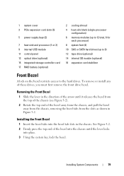
... drive bezel. 1 system cover 3 PCIe expansion card slots (5) 5 power supply bays (2) 7 heat sink and processor (1 or 2) 9 internal USB module 11 control panel 13 optical drive (optional) 15 integrated storage controller card 17 RAID battery (optional) 2 cooling shroud 4 heat sink blank (single-processor configuration) 6 memory modules (up to 12 total, 6 for each processor) 8 system...
... drive bezel. 1 system cover 3 PCIe expansion card slots (5) 5 power supply bays (2) 7 heat sink and processor (1 or 2) 9 internal USB module 11 control panel 13 optical drive (optional) 15 integrated storage controller card 17 RAID battery (optional) 2 cooling shroud 4 heat sink blank (single-processor configuration) 6 memory modules (up to 12 total, 6 for each processor) 8 system...
Hardware Owner's Manual
Page 84
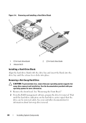
See "Removing the Front Bezel." 2 From the RAID management software, prepare the drive for information about hot-swap drive removal. 84 Installing System Components Removing and Installing a Hard Drive Blank 1 2 3 3 1 3.5-in hard drive ... removed safely. Wait until the release lever clicks into the drive bay until the hard-drive indicators on the hard-drive carrier signal that your controller documentation for removal. See your operating system supports hotswap drive removal and installation. Figure 3-4. See the documentation provided with the drive bay and insert the...
See "Removing the Front Bezel." 2 From the RAID management software, prepare the drive for information about hot-swap drive removal. 84 Installing System Components Removing and Installing a Hard Drive Blank 1 2 3 3 1 3.5-in hard drive ... removed safely. Wait until the release lever clicks into the drive bay until the hard-drive indicators on the hard-drive carrier signal that your controller documentation for removal. See your operating system supports hotswap drive removal and installation. Figure 3-4. See the documentation provided with the drive bay and insert the...
Hardware Owner's Manual
Page 112
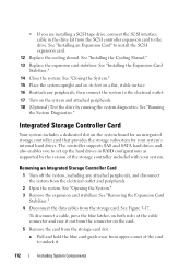
... . 112 Installing System Components • If you to unlock it out from the connector on the system board for an integrated storage controller card that provides the storage subsystem for your system. See "Closing the System." 15 Place the system upright and on its feet on... drives and also enables you are installing a SCSI tape drive, connect the SCSI interface cable in RAID configurations as supported by running the system diagnostics. Removing an Integrated Storage Controller Card 1 Turn off the system, including any peripherals, then connect the system to the drive. See...
... . 112 Installing System Components • If you to unlock it out from the connector on the system board for an integrated storage controller card that provides the storage subsystem for your system. See "Closing the System." 15 Place the system upright and on its feet on... drives and also enables you are installing a SCSI tape drive, connect the SCSI interface cable in RAID configurations as supported by running the system diagnostics. Removing an Integrated Storage Controller Card 1 Turn off the system, including any peripherals, then connect the system to the drive. See...
Hardware Owner's Manual
Page 113
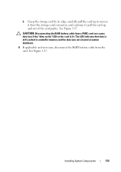
b Grasp the storage card by its edge, carefully pull the card up and out of the card guides. CAUTION: Disconnecting the RAID battery cable from a PERC card can cause data loss if the "dirty cache" LED on the card is still cached in controller memory and the data was not cleared at system shutdown. 6 If applicable and necessary, disconnect the RAID battery cable from the storage-card connector, and continue to pull the card up to remove it from the card. Installing System Components 113 See Figure 3-17. The LED indicates that data is lit. See Figure 3-17.
b Grasp the storage card by its edge, carefully pull the card up and out of the card guides. CAUTION: Disconnecting the RAID battery cable from a PERC card can cause data loss if the "dirty cache" LED on the card is still cached in controller memory and the data was not cleared at system shutdown. 6 If applicable and necessary, disconnect the RAID battery cable from the storage-card connector, and continue to pull the card up to remove it from the card. Installing System Components 113 See Figure 3-17. The LED indicates that data is lit. See Figure 3-17.
Hardware Owner's Manual
Page 114
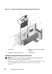
Figure 3-17. Removing and Installing an Integrated Storage Controller Card 1 2 3 4 1 data cables 3 integrated storage controller card 2 RAID battery cable connector (PERC card only) 4 card guides (2) Installing an Integrated Storage Controller Card NOTE: Be sure to connect the cables according to the connector on the cables. The cables are not operational if reversed. 1 If applicable, install the RAID battery (see "Installing a RAID Battery") and connect the RAID battery cable to the connector labels on the card. See Figure 3-17. 114 Installing System Components
Figure 3-17. Removing and Installing an Integrated Storage Controller Card 1 2 3 4 1 data cables 3 integrated storage controller card 2 RAID battery cable connector (PERC card only) 4 card guides (2) Installing an Integrated Storage Controller Card NOTE: Be sure to connect the cables according to the connector on the cables. The cables are not operational if reversed. 1 If applicable, install the RAID battery (see "Installing a RAID Battery") and connect the RAID battery cable to the connector labels on the card. See Figure 3-17. 114 Installing System Components
Hardware Owner's Manual
Page 116
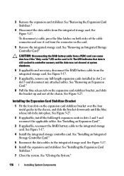
... If applicable and necessary, disconnect the RAID battery cable from the integrated storage card. See "Installing an Integrated Storage Controller Card." 5 Reconnect the data cables to the integrated storage card. See "Removing an Integrated Storage Controller Card." See "Installing the Expansion Card... Stabilizer." 7 Close the system. CAUTION: Disconnecting the RAID battery cable from the connector on the expansion card stabilizer bracket, and ...
... If applicable and necessary, disconnect the RAID battery cable from the integrated storage card. See "Installing an Integrated Storage Controller Card." 5 Reconnect the data cables to the integrated storage card. See "Removing an Integrated Storage Controller Card." See "Installing the Expansion Card... Stabilizer." 7 Close the system. CAUTION: Disconnecting the RAID battery cable from the connector on the expansion card stabilizer bracket, and ...
Hardware Owner's Manual
Page 117
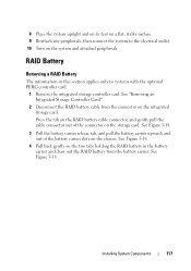
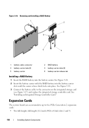
See "Removing an Integrated Storage Controller Card." 2 Disconnect the RAID battery cable from the battery carrier. Press the tab on the RAID battery cable connector, and gently pull the cable connector out of the battery carrier slots on the system and attached ...integrated storage controller card. See Figure 3-18. 3 Pull the battery carrier release tab, and pull the battery carrier upwards and out of the connector on the integrated storage card. See Figure 3-18. RAID Battery Removing a RAID Battery The information in the battery carrier and draw out the RAID battery from...
See "Removing an Integrated Storage Controller Card." 2 Disconnect the RAID battery cable from the battery carrier. Press the tab on the RAID battery cable connector, and gently pull the cable connector out of the battery carrier slots on the system and attached ...integrated storage controller card. See Figure 3-18. 3 Pull the battery carrier release tab, and pull the battery carrier upwards and out of the connector on the integrated storage card. See Figure 3-18. RAID Battery Removing a RAID Battery The information in the battery carrier and draw out the RAID battery from...
Hardware Owner's Manual
Page 118
...Two full-height, full-length (12.2-inch) PCIe x8 link (slots 2 and 3) 118 Installing System Components See "Installing an Integrated Storage Controller Card." Expansion Cards The system board can accommodate up to the connector on the integrated storage card (see Figure 3-17) and replace the ...integrated storage controller card. Figure 3-18. See Figure 3-18. 2 Insert the battery carrier with the RAID battery into the battery carrier slots until the carrier release latch locks into the battery carrier...
...Two full-height, full-length (12.2-inch) PCIe x8 link (slots 2 and 3) 118 Installing System Components See "Installing an Integrated Storage Controller Card." Expansion Cards The system board can accommodate up to the connector on the integrated storage card (see Figure 3-17) and replace the ...integrated storage controller card. Figure 3-18. See Figure 3-18. 2 Insert the battery carrier with the RAID battery into the battery carrier slots until the carrier release latch locks into the battery carrier...


