Getting Started Guide
Page 5
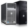
... of 512-MB, 1-GB, 2-GB, or 4-GB memory modules in a 1 + 1 redundant configuration. See the Hardware Owner's Manual. • A minimum of 1 GB (single-processor systems) or 2 GB (two-processor systems) of 533 or 667 MHz registered parity DDR-II memory modules. Getting Started With Your System 3 NOTE: DVD ...A controller expansion card is opened. • A 650-W non-redundant power supply, or an optional hot-pluggable 675-W power supply in the eight memory module sockets on the system board. • Support for the following supported drives: DVD-ROM, combination CD-RW/DVD, DVD+RW, or tape...
... of 512-MB, 1-GB, 2-GB, or 4-GB memory modules in a 1 + 1 redundant configuration. See the Hardware Owner's Manual. • A minimum of 1 GB (single-processor systems) or 2 GB (two-processor systems) of 533 or 667 MHz registered parity DDR-II memory modules. Getting Started With Your System 3 NOTE: DVD ...A controller expansion card is opened. • A 650-W non-redundant power supply, or an optional hot-pluggable 675-W power supply in the eight memory module sockets on the system board. • Support for the following supported drives: DVD-ROM, combination CD-RW/DVD, DVD+RW, or tape...

Getting Started Guide
Page 14
Video Video type Video memory Power AC power supply Wattage Voltage Heat dissipation CMOS backup battery Physical Height Width Depth Weight (maximum configuration) Integrated 32 MB (minimum) 650 W (non-redundant power supply) 675 W (redundant power supply) 100-240VAC, 6.0-3.0A, 50/60 Hz 624 BTU/Hour (non-redundant power supply) 574 BTU/Hour (redundant power supply) CR 2032 3.0-V lithium ion coin cell 456 mm (17.95 inches) 210 mm (8.27 inches) 635 mm (25 inches) 27 kg (59.52 lb) 12 Getting Started With Your System
Video Video type Video memory Power AC power supply Wattage Voltage Heat dissipation CMOS backup battery Physical Height Width Depth Weight (maximum configuration) Integrated 32 MB (minimum) 650 W (non-redundant power supply) 675 W (redundant power supply) 100-240VAC, 6.0-3.0A, 50/60 Hz 624 BTU/Hour (non-redundant power supply) 574 BTU/Hour (redundant power supply) CR 2032 3.0-V lithium ion coin cell 456 mm (17.95 inches) 210 mm (8.27 inches) 635 mm (25 inches) 27 kg (59.52 lb) 12 Getting Started With Your System
Hardware Owner's Manual (PDF)
Page 4
... to Error Messages 43 Using the System Setup Program 44 System Setup Options 44 Main Screen 44 Memory Information Screen 47 CPU Information Screen 48 SATA Configuration Screen 50 Integrated Devices Screen 51 Serial Communication Screen 52 System Security Screen 53 Exit Screen 56 ... Setup Password Features 56 Using the System Password 56 Using the Setup Password 59 Disabling a Forgotten Password 60 Baseboard Management Controller Configuration 60 Entering the BMC Setup Module 61 BMC Setup Module Options 61 3 Installing System Components 63 Recommended Tools 64 Inside the ...
... to Error Messages 43 Using the System Setup Program 44 System Setup Options 44 Main Screen 44 Memory Information Screen 47 CPU Information Screen 48 SATA Configuration Screen 50 Integrated Devices Screen 51 Serial Communication Screen 52 System Security Screen 53 Exit Screen 56 ... Setup Password Features 56 Using the System Password 56 Using the Setup Password 59 Disabling a Forgotten Password 60 Baseboard Management Controller Configuration 60 Entering the BMC Setup Module 61 BMC Setup Module Options 61 3 Installing System Components 63 Recommended Tools 64 Inside the ...
Hardware Owner's Manual (PDF)
Page 6
... 114 RAID Battery 114 Installing a RAID Battery 115 Removing a RAID Battery 116 Configuring the Boot Device 117 RAC Card 117 Removing the RAC Card 117 Installing a RAC Card 119 Internal USB Memory Key Connector 120 Installing the Optional Internal USB Memory Key 120 Integrated TOE 122 Cooling Fans 122 Removing the Expansion Card...
... 114 RAID Battery 114 Installing a RAID Battery 115 Removing a RAID Battery 116 Configuring the Boot Device 117 RAC Card 117 Removing the RAC Card 117 Installing a RAC Card 119 Internal USB Memory Key Connector 120 Installing the Optional Internal USB Memory Key 120 Integrated TOE 122 Cooling Fans 122 Removing the Expansion Card...
Hardware Owner's Manual (PDF)
Page 28
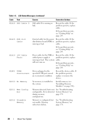
... persists, see "Getting Help" on . They system cable. Memory detected, but See "Troubleshooting not usable. configuration. Power cable for the power Reseat the cable. Error detected System Memory" on page 205. Memory System Memory" on page 205. page 174. 28 About Your System If...Cable D E1A18 PDB Ctrl Cable E1A19 12V Cable Fault E1B01 USB# Overcurrent E2010 No Memory E2011 Mem Config Err E2012 Unusable Memory Causes Corrective Actions SAS cable D is configured, but is problem persists, replace missing or bad. Control cable for the PDB or...
... persists, see "Getting Help" on . They system cable. Memory detected, but See "Troubleshooting not usable. configuration. Power cable for the power Reseat the cable. Error detected System Memory" on page 205. Memory System Memory" on page 205. page 174. 28 About Your System If...Cable D E1A18 PDB Ctrl Cable E1A19 12V Cable Fault E1B01 USB# Overcurrent E2010 No Memory E2011 Mem Config Err E2012 Unusable Memory Causes Corrective Actions SAS cable D is configured, but is problem persists, replace missing or bad. Control cable for the PDB or...

Hardware Owner's Manual (PDF)
Page 30
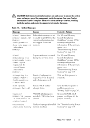
... Messages (continued) Code Text Causes Corrective Actions E201F DRAC Config Dell remote access controller (DRAC) configuration failure. E2020 CPU Config Processor configuration failure. Memory population order incorrect. E2021 Memory Population Incorrect memory configuration. E2111 SBE Log Disable DIMM # The system BIOS has See "Troubleshooting disabled memory single-bit System Memory" on has had too many errors. E2110 MBE DIMM...
... Messages (continued) Code Text Causes Corrective Actions E201F DRAC Config Dell remote access controller (DRAC) configuration failure. E2020 CPU Config Processor configuration failure. Memory population order incorrect. E2021 Memory Population Incorrect memory configuration. E2111 SBE Log Disable DIMM # The system BIOS has See "Troubleshooting disabled memory single-bit System Memory" on has had too many errors. E2110 MBE DIMM...
Hardware Owner's Manual (PDF)
Page 33
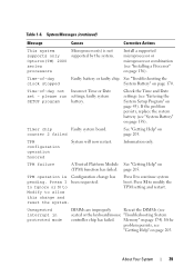
... jumper is installed on page 174. CMOS has been cleared. About Your System 33 Memory" on page 205. If the problem persists, see "Troubleshooting System Memory" on page 127 for memory configuration information. Attempting to reconfigure redundant memory. Redundant memory was previously lost. If problem persists, see Figure 6-1 for complete information about safety precautions, working inside...
... jumper is installed on page 174. CMOS has been cleared. About Your System 33 Memory" on page 205. If the problem persists, see "Troubleshooting System Memory" on page 127 for memory configuration information. Attempting to reconfigure redundant memory. Redundant memory was previously lost. If problem persists, see Figure 6-1 for complete information about safety precautions, working inside...
Hardware Owner's Manual (PDF)
Page 39
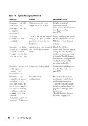
... Table 1-6. System Messages (continued) Message Causes Corrective Actions This system supports only Opteron(TM) 2000 series processors Microprocessor(s) is Configuration change and reset the system. Time-of -day clock stopped Faulty battery or faulty chip. If the problem persists, replace ...setting and restart. Unexpected interrupt in protected mode DIMMs are improperly Reseat the DIMMs (see "Installing a Processor" on page 205. Memory" on page 170. please run settings; Press I been requested. About Your System 39 See "Troubleshooting the System Battery" on page...
... Table 1-6. System Messages (continued) Message Causes Corrective Actions This system supports only Opteron(TM) 2000 series processors Microprocessor(s) is Configuration change and reset the system. Time-of -day clock stopped Faulty battery or faulty chip. If the problem persists, replace ...setting and restart. Unexpected interrupt in protected mode DIMMs are improperly Reseat the DIMMs (see "Installing a Processor" on page 205. Memory" on page 170. please run settings; Press I been requested. About Your System 39 See "Troubleshooting the System Battery" on page...
Hardware Owner's Manual (PDF)
Page 40
... on the boot hard drive (see the system documentation on valid memory configurations, please see the CDs that came with your system). For more information on support.dell.com Invalid memory configuration. restart. section in "Troubleshooting Your System" on page 159 for... any faulty components specified in a valid configuration (see "Processors" on page 205). If the problem persists...
... on the boot hard drive (see the system documentation on valid memory configurations, please see the CDs that came with your system). For more information on support.dell.com Invalid memory configuration. restart. section in "Troubleshooting Your System" on page 159 for... any faulty components specified in a valid configuration (see "Processors" on page 205). If the problem persists...
Hardware Owner's Manual (PDF)
Page 43
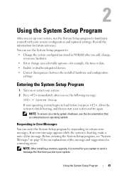
...while the system is normal for example, the time or date • Enable or disable integrated devices • Correct discrepancies between the installed hardware and configuration settings Entering the System Setup Program 1 Turn on page 32 for an explanation of the message. Record the information for correcting errors. NOTE: To ... system, run the System Setup program to send a message the first time you press , allow the system to certain error messages. NOTE: After installing a memory upgrade, it is booting, make a note of the message and suggestions for future reference.
...while the system is normal for example, the time or date • Enable or disable integrated devices • Correct discrepancies between the installed hardware and configuration settings Entering the System Setup Program 1 Turn on page 32 for an explanation of the message. Record the information for correcting errors. NOTE: To ... system, run the System Setup program to send a message the first time you press , allow the system to certain error messages. NOTE: After installing a memory upgrade, it is booting, make a note of the message and suggestions for future reference.
Hardware Owner's Manual (PDF)
Page 46
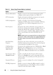
... related to Enabled, the system re-attempts the boot sequence after a 30-second timeout if the previous boot attempt failed. See support.dell.com for a USB flash drive. Displays a screen to a SAS or SCSI adapter. Determines the order in your system. If you...boot devices during system startup. Displays a screen to change the IRQ assigned to configure certain memory features (see Table 2-3). System Setup Program Options (continued) Option Memory Information CPU Information SATA Configuration Boot Sequence Hard-Disk Drive Sequence USB Flash Drive Emulation Type (Auto default) ...
... related to Enabled, the system re-attempts the boot sequence after a 30-second timeout if the previous boot attempt failed. See support.dell.com for a USB flash drive. Displays a screen to a SAS or SCSI adapter. Determines the order in your system. If you...boot devices during system startup. Displays a screen to change the IRQ assigned to configure certain memory features (see Table 2-3). System Setup Program Options (continued) Option Memory Information CPU Information SATA Configuration Boot Sequence Hard-Disk Drive Sequence USB Flash Drive Emulation Type (Auto default) ...
Hardware Owner's Manual (PDF)
Page 47
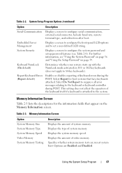
... Screen Table 2-3 lists the descriptions for host systems that appear on the Memory Information screen. Displays the type of system memory. Using the System Setup Program 47 Select Do Not Report to suppress all error messages relating to configure the system password and setup password features (see "Using the System Password" on page...
... Screen Table 2-3 lists the descriptions for host systems that appear on the Memory Information screen. Displays the type of system memory. Using the System Setup Program 47 Select Do Not Report to suppress all error messages relating to configure the system password and setup password features (see "Using the System Password" on page...
Hardware Owner's Manual (PDF)
Page 48
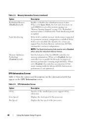
.... Table 2-4. Displays the bus speed of the processors. If this field is enabled, memory interleaving is supported if a symmetric memory configuration is enabled. When set to disabled (the default), the system can support Non-Uniform Memory architecture (NUMA) (asymmetric) memory configurations. Redundant memory feature is disabled if the Node Interleaving field is installed. CPU Information Screen Table...
.... Table 2-4. Displays the bus speed of the processors. If this field is enabled, memory interleaving is supported if a symmetric memory configuration is enabled. When set to disabled (the default), the system can support Non-Uniform Memory architecture (NUMA) (asymmetric) memory configurations. Redundant memory feature is disabled if the Node Interleaving field is installed. CPU Information Screen Table...
Hardware Owner's Manual (PDF)
Page 120
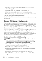
... key, or mass storage device. The USB memory key can be enabled in the System Setup program. See your Product Information Guide for complete information about safety precautions, working inside the system. See "Opening the System" on configuring and using the RAC card. See the RAC... card documentation for use the internal USB connector, the Internal USB Port option must configure the USB memory key with a USB flash memory key. Installing the Optional Internal USB Memory Key CAUTION: Only trained service technicians are authorized to the electrical outlet. 10 Turn on its...
... key, or mass storage device. The USB memory key can be enabled in the System Setup program. See your Product Information Guide for complete information about safety precautions, working inside the system. See "Opening the System" on configuring and using the RAC card. See the RAC... card documentation for use the internal USB connector, the Internal USB Port option must configure the USB memory key with a USB flash memory key. Installing the Optional Internal USB Memory Key CAUTION: Only trained service technicians are authorized to the electrical outlet. 10 Turn on its...
Hardware Owner's Manual (PDF)
Page 122
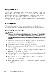
... the TOE key; See "Installing the Expansion Card Fan" on the chassis. 6 Press and hold the fan release tab, and slide the fan up and configure the TOE feature. See "Installing and Removing a RAID Battery" on page 116. 5 Disconnect the fan's power cable from the system board, and un-route... Card Fan CAUTION: Only trained service technicians are authorized to set up and out of the securing slots (see Figure 6-1 for the processor and memory modules. See "Opening the System" on the system board. See the user documentation that came with the hardware key for information on how to ...
... the TOE key; See "Installing the Expansion Card Fan" on the chassis. 6 Press and hold the fan release tab, and slide the fan up and configure the TOE feature. See "Installing and Removing a RAID Battery" on page 116. 5 Disconnect the fan's power cable from the system board, and un-route... Card Fan CAUTION: Only trained service technicians are authorized to set up and out of the securing slots (see Figure 6-1 for the processor and memory modules. See "Opening the System" on the system board. See the user documentation that came with the hardware key for information on how to ...
Hardware Owner's Manual (PDF)
Page 127
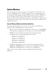
You can upgrade your system memory. • Memory must be installed in configurations of two, four, or eight DIMMs. The minimum configuration for a two-processor configuration). Table 3-1 shows the available memory configurations following these guidelines. Each four-socket group is four DIMMs. • DIMMs must occupy the lower-numbered sockets (DIMM A1 and DIMM A2 for a one-...
You can upgrade your system memory. • Memory must be installed in configurations of two, four, or eight DIMMs. The minimum configuration for a two-processor configuration). Table 3-1 shows the available memory configurations following these guidelines. Each four-socket group is four DIMMs. • DIMMs must occupy the lower-numbered sockets (DIMM A1 and DIMM A2 for a one-...
Hardware Owner's Manual (PDF)
Page 128
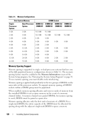
... act as spares also. See "Entering the System Setup Program" on the same sides of a memory channel failure. When enabled, memory sparing allocates and reserves ranks of the DIMM must disable node interleaving. Table 3-1. Memory Configurations Total System Memory DIMM Socket SingleProcessor System Dual-Processor DIMM A1/ DIMM A2/ DIMM A3/ DIMM A4/ System DIMM...
... act as spares also. See "Entering the System Setup Program" on the same sides of a memory channel failure. When enabled, memory sparing allocates and reserves ranks of the DIMM must disable node interleaving. Table 3-1. Memory Configurations Total System Memory DIMM Socket SingleProcessor System Dual-Processor DIMM A1/ DIMM A2/ DIMM A3/ DIMM A4/ System DIMM...
Hardware Owner's Manual (PDF)
Page 129
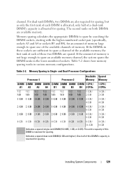
... the amount of this DIMM is not large enough to spare an available memory channel, the system spares the DIMM ranks in these sockets are spared. and Dual-Processor Configurations Processor 1 Processor 2 Available Spared Memory Memory DIMM DIMM DIMM DIMM DIMM DIMM DIMM DIMM 1 CPU / A1 A2 ... GB 4 GB 4 GB 4 GB 8 GB / 16 GB 4 GB / 8 GB Indicates a spared single-rank DIMM (512-MB, 1-GB, or 2-GB). One-half of memory is reserved for sparing. Memory Sparing in various memory configurations. The second ranks on both DIMMs are also required for sparing. Table 3-2. channel.
... the amount of this DIMM is not large enough to spare an available memory channel, the system spares the DIMM ranks in these sockets are spared. and Dual-Processor Configurations Processor 1 Processor 2 Available Spared Memory Memory DIMM DIMM DIMM DIMM DIMM DIMM DIMM DIMM 1 CPU / A1 A2 ... GB 4 GB 4 GB 4 GB 8 GB / 16 GB 4 GB / 8 GB Indicates a spared single-rank DIMM (512-MB, 1-GB, or 2-GB). One-half of memory is reserved for sparing. Memory Sparing in various memory configurations. The second ranks on both DIMMs are also required for sparing. Table 3-2. channel.
Hardware Owner's Manual (PDF)
Page 154
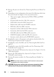
... heat sink to ensure proper reinstallation of the memory modules. See "Removing the Processor Shroud" on page 72. 5 Depending on page 107. 7 If applicable, remove the RAC card. See "Removing an Expansion Card" on your configuration, disconnect the following cables from the INTRUSION connector... 6 If applicable, remove all memory modules. See "Removing the RAC Card" on page 117. 8 If applicable, remove the SAS controller ...
... heat sink to ensure proper reinstallation of the memory modules. See "Removing the Processor Shroud" on page 72. 5 Depending on page 107. 7 If applicable, remove the RAC card. See "Removing an Expansion Card" on your configuration, disconnect the following cables from the INTRUSION connector... 6 If applicable, remove all memory modules. See "Removing the RAC Card" on page 117. 8 If applicable, remove the SAS controller ...
Hardware Owner's Manual (PDF)
Page 156
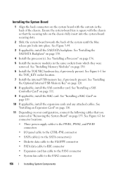
.... 10 If applicable, install the expansion cards and any attached cables. See "Installing an Expansion Card" on page 110. 11 Depending on your configuration, connect the following cables that the securing tabs on the chassis fully insert into the system-board securing slots. 2 Slide the system board towards .... Installing the System Board 1 Align the back connectors on page 130. 6 Install the TOE NIC hardware key, if previously present. See "Installing Memory Modules" on the system board with the chassis so that you removed in the back of the system until the blue release pin locks into...
.... 10 If applicable, install the expansion cards and any attached cables. See "Installing an Expansion Card" on page 110. 11 Depending on your configuration, connect the following cables that the securing tabs on the chassis fully insert into the system-board securing slots. 2 Slide the system board towards .... Installing the System Board 1 Align the back connectors on page 130. 6 Install the TOE NIC hardware key, if previously present. See "Installing Memory Modules" on the system board with the chassis so that you removed in the back of the system until the blue release pin locks into...


