
Getting Started Guide
Page 6
... Started With Your System graphics are data only. • One 133-MHz PCI-X expansion slot, three PCI Express (PCIe) x4 expansion slots, and one NIC connector. • Front-panel connectors include two USB connectors. • Front-panel LCD for system ID and error messaging. The system board includes the following integrated features: • SATA controller that supports up to two cabled SATA hard drives, and up to two of supporting a diskette drive, a DVD-ROM drive, a keyboard, a mouse, or a USB flash drive. • Optional Remote Access Controller (RAC...
... Started With Your System graphics are data only. • One 133-MHz PCI-X expansion slot, three PCI Express (PCIe) x4 expansion slots, and one NIC connector. • Front-panel connectors include two USB connectors. • Front-panel LCD for system ID and error messaging. The system board includes the following integrated features: • SATA controller that supports up to two cabled SATA hard drives, and up to two of supporting a diskette drive, a DVD-ROM drive, a keyboard, a mouse, or a USB flash drive. • Optional Remote Access Controller (RAC...
Hardware Owner's Manual (PDF)
Page 40
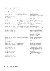
... the boot hard drive (see "Processors" on support.dell.com Invalid memory configuration. restart. See the Please check the applicable troubleshooting system event log! Warning: A fatal A fatal system error occurred Check the SEL for error has caused and caused the system to information that came with your system). Warning! Utility partition not available The key was logged system reset! during POST, but no utility partition exists on page 205). No micro Micro code update failed. Install a supported microprocessor...
... the boot hard drive (see "Processors" on support.dell.com Invalid memory configuration. restart. See the Please check the applicable troubleshooting system event log! Warning: A fatal A fatal system error occurred Check the SEL for error has caused and caused the system to information that came with your system). Warning! Utility partition not available The key was logged system reset! during POST, but no utility partition exists on page 205). No micro Micro code update failed. Install a supported microprocessor...
Hardware Owner's Manual (PDF)
Page 46
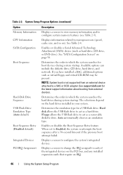
... disk allows the USB flash drive to act as virtual floppy and virtual CD-ROM may be present. Enables or disables the Boot Sequence Retry feature. System Setup Program Options (continued) Option Memory Information CPU Information SATA Configuration Boot Sequence Hard-Disk Drive Sequence USB Flash Drive Emulation Type (Auto default) Boot Sequence Retry (Disabled default) Integrated Devices PCI IRQ Assignment Description Displays a screen to view memory information and to a SAS or SCSI adapter. Enables or disables a Serial Advanced Technology Attachment (SATA) device (such as a hard drive...
... disk allows the USB flash drive to act as virtual floppy and virtual CD-ROM may be present. Enables or disables the Boot Sequence Retry feature. System Setup Program Options (continued) Option Memory Information CPU Information SATA Configuration Boot Sequence Hard-Disk Drive Sequence USB Flash Drive Emulation Type (Auto default) Boot Sequence Retry (Disabled default) Integrated Devices PCI IRQ Assignment Description Displays a screen to view memory information and to a SAS or SCSI adapter. Enables or disables a Serial Advanced Technology Attachment (SATA) device (such as a hard drive...

Hardware Owner's Manual (PDF)
Page 50
... enabled if devices are also unchoosable. Displays the model number, drive type, and size of the device attached to Port C. The driver is installed in the system, the SATA Configuration screen changes. Port A, Port B, Port C, and Port D display off is the default), the port is enabled if devices are attached to Off or QDMA mode. Off disables the SATA subsystem. When set to the port. When the SAS Card is enabled if devices are attached to the port. 50 Using the System Setup Program Displays the model number, drive type...
... enabled if devices are also unchoosable. Displays the model number, drive type, and size of the device attached to Port C. The driver is installed in the system, the SATA Configuration screen changes. Port A, Port B, Port C, and Port D display off is the default), the port is enabled if devices are attached to Off or QDMA mode. Off disables the SATA subsystem. When set to the port. When the SAS Card is enabled if devices are attached to the port. 50 Using the System Setup Program Displays the model number, drive type...

Hardware Owner's Manual (PDF)
Page 51
... on the system board. Diskette Controller (Auto default) Enables or disables the integrated diskette drive controller. Internal USB Port (On default) Enables or disables the system's internal USB port. Options are All Ports On, Only Back Ports On, and All Ports Off. Using the System Setup Program 51 Embedded Gb NICx (NIC1 default: Enabled with iSCSI Boot, and Disabled. PXE support allows the system to boot from the network. Capability Detected Displays the NIC features provided by the LOM NIC hardware key installed in the TOE_KEY...
... on the system board. Diskette Controller (Auto default) Enables or disables the integrated diskette drive controller. Internal USB Port (On default) Enables or disables the system's internal USB port. Options are All Ports On, Only Back Ports On, and All Ports Off. Using the System Setup Program 51 Embedded Gb NICx (NIC1 default: Enabled with iSCSI Boot, and Disabled. PXE support allows the system to boot from the network. Capability Detected Displays the NIC features provided by the LOM NIC hardware key installed in the TOE_KEY...
Hardware Owner's Manual (PDF)
Page 56
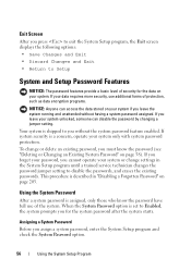
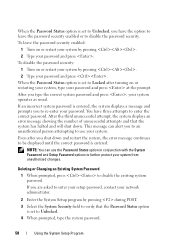
... is shipped to Setup System and Setup Password Features NOTICE: The password features provide a basic level of protection, such as data encryption programs. NOTICE: Anyone can disable the password by changing a jumper setting. To change settings in "Disabling a Forgotten Password" on page 58). Exit Screen After you for the data on your system if you cannot operate your system unlocked, someone can access the data stored on your...
... is shipped to Setup System and Setup Password Features NOTICE: The password features provide a basic level of protection, such as data encryption programs. NOTICE: Anyone can disable the password by changing a jumper setting. To change settings in "Disabling a Forgotten Password" on page 58). Exit Screen After you for the data on your system if you cannot operate your system unlocked, someone can access the data stored on your...
Hardware Owner's Manual (PDF)
Page 58
..., type the system password. 58 Using the System Setup Program After the third unsuccessful attempt, the system displays an error message showing the number of unsuccessful attempts and that the Password Status option is set to disable the existing system password. After you shut down . Even after turning on or restart your system by pressing . 2 Type your network administrator. 2 Enter the System Setup program by pressing during POST...
..., type the system password. 58 Using the System Setup Program After the third unsuccessful attempt, the system displays an error message showing the number of unsuccessful attempts and that the Password Status option is set to disable the existing system password. After you shut down . Even after turning on or restart your system by pressing . 2 Type your network administrator. 2 Enter the System Setup program by pressing during POST...

Hardware Owner's Manual (PDF)
Page 63
...: • Front drive bezel • Cooling shrouds • Power supplies • Hard drives • Diskette drive • Optical and tape drives • Expansion cards • SAS controller card • RAID battery • RAC card • Internal USB memory key • Expansion card fan • System fan • Memory • Integrated TCP/IP Offload Engine (TOE) • Processors • System battery • Chassis intrusion switch • Power distribution board • SAS/SATA backplane • Control panel • System board Installing System Components 63
...: • Front drive bezel • Cooling shrouds • Power supplies • Hard drives • Diskette drive • Optical and tape drives • Expansion cards • SAS controller card • RAID battery • RAC card • Internal USB memory key • Expansion card fan • System fan • Memory • Integrated TCP/IP Offload Engine (TOE) • Processors • System battery • Chassis intrusion switch • Power distribution board • SAS/SATA backplane • Control panel • System board Installing System Components 63
Hardware Owner's Manual (PDF)
Page 111
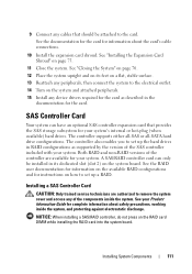
... See the documentation for the card for complete information about the card's cable connections. 10 Install the expansion card shroud. SAS Controller Card Your system can only be attached to set up the hard drives in RAID configurations as described in its feet on a flat, stable surface. 13 Reattach any peripherals, then connect the system to remove the system cover and access any device drivers required for the card as supported by the version of the...
... See the documentation for the card for complete information about the card's cable connections. 10 Install the expansion card shroud. SAS Controller Card Your system can only be attached to set up the hard drives in RAID configurations as described in its feet on a flat, stable surface. 13 Reattach any peripherals, then connect the system to remove the system cover and access any device drivers required for the card as supported by the version of the...

Hardware Owner's Manual (PDF)
Page 117
... the RAID battery from external devices. RAC Card The optional Remote Access Controller (RAC) provides a set of advanced features for installed boot devices. The device that the system uses to a SAS or SCSI adapter. Removing the RAC Card CAUTION: Only trained service technicians are authorized to remove the system cover and access any attached peripherals, and disconnect the system from an external device attached to scan for managing the server remotely. Installing System Components 117 The System Setup...
... the RAID battery from external devices. RAC Card The optional Remote Access Controller (RAC) provides a set of advanced features for installed boot devices. The device that the system uses to a SAS or SCSI adapter. Removing the RAC Card CAUTION: Only trained service technicians are authorized to remove the system cover and access any attached peripherals, and disconnect the system from an external device attached to scan for managing the server remotely. Installing System Components 117 The System Setup...
Hardware Owner's Manual (PDF)
Page 164
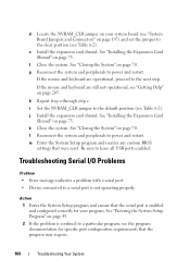
... set the jumper to power and restart. Action 1 Enter the System Setup program and ensure that the serial port is enabled and configured correctly for specific port configuration requirements that were reset. Troubleshooting Serial I/O Problems Problem • Error message indicates a problem with a serial port. • Device connected to leave all USB ports enabled. f Close the system. See "Closing the System" on page 75. If the mouse and keyboard are operational, proceed to a particular program, see the program documentation for...
... set the jumper to power and restart. Action 1 Enter the System Setup program and ensure that the serial port is enabled and configured correctly for specific port configuration requirements that were reset. Troubleshooting Serial I/O Problems Problem • Error message indicates a problem with a serial port. • Device connected to leave all USB ports enabled. f Close the system. See "Closing the System" on page 75. If the mouse and keyboard are operational, proceed to a particular program, see the program documentation for...
Hardware Owner's Manual (PDF)
Page 165
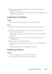
... not operating properly. If the problem persists, see "Troubleshooting a USB Device" on page 205. If the problem is not operating properly. See "Getting Help" on page 205. 3 Turn off the system and any peripheral devices connected to the serial port is resolved, replace the serial device. See "Running the System Diagnostics" on the system and the serial device. If the problem is resolved, replace the interface cable. Troubleshooting Your System 165 3 Run the appropriate online diagnostic test.
... not operating properly. If the problem persists, see "Troubleshooting a USB Device" on page 205. If the problem is not operating properly. See "Getting Help" on page 205. 3 Turn off the system and any peripheral devices connected to the serial port is resolved, replace the serial device. See "Running the System Diagnostics" on the system and the serial device. If the problem is resolved, replace the interface cable. Troubleshooting Your System 165 3 Run the appropriate online diagnostic test.
Hardware Owner's Manual (PDF)
Page 168
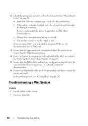
... you are enabled. See the NIC's documentation. 4 Enter the System Setup program and confirm that the appropriate drivers are installed and the protocols are of an integrated NIC, see "Getting Help" on the network are all network cables are bound. See the NIC's documentation. • Change the autonegotiation setting, if possible. • Use another connector on the system. • Excessive humidity. 168 Troubleshooting Your System 2 Check the appropriate...
... you are enabled. See the NIC's documentation. 4 Enter the System Setup program and confirm that the appropriate drivers are installed and the protocols are of an integrated NIC, see "Getting Help" on the network are all network cables are bound. See the NIC's documentation. • Change the autonegotiation setting, if possible. • Use another connector on the system. • Excessive humidity. 168 Troubleshooting Your System 2 Check the appropriate...
Hardware Owner's Manual (PDF)
Page 170
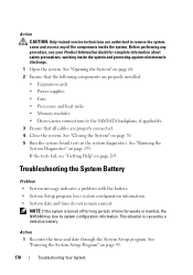
...; Power supplies • Fans • Processors and heat sinks • Memory modules • Drive-carrier connections to the SAS/SATA backplane, if applicable 3 Ensure that all cables are authorized to remove the system cover and access any procedure, see "Getting Help" on page 205. Action 1 Re-enter the time and date through the System Setup program. See "Opening the System" on page 70. 5 Run the system board tests in the system diagnostics. Troubleshooting...
...; Power supplies • Fans • Processors and heat sinks • Memory modules • Drive-carrier connections to the SAS/SATA backplane, if applicable 3 Ensure that all cables are authorized to remove the system cover and access any procedure, see "Getting Help" on page 205. Action 1 Re-enter the time and date through the System Setup program. See "Opening the System" on page 70. 5 Run the system board tests in the system diagnostics. Troubleshooting...

Hardware Owner's Manual (PDF)
Page 172
...; System cover, drive blanks, or shrouds are installed. The system is powered on. Troubleshooting System Cooling Problems Problem • Systems management software issues a fan-related error message. See "Troubleshooting a Fan" on page 205. Remove and install only one power supply installed for the system to signify that none of time can hot-plug the redundant power supplies. See "Removing a Redundant Power Supply" on page 77. Action Ensure that the power supply is working properly. See "Installing a Redundant Power Supply" on...
...; System cover, drive blanks, or shrouds are installed. The system is powered on. Troubleshooting System Cooling Problems Problem • Systems management software issues a fan-related error message. See "Troubleshooting a Fan" on page 205. Remove and install only one power supply installed for the system to signify that none of time can hot-plug the redundant power supplies. See "Removing a Redundant Power Supply" on page 77. Action Ensure that the power supply is working properly. See "Installing a Redundant Power Supply" on...

Hardware Owner's Manual (PDF)
Page 180
... tape drive's interface/DC power cable is connected to the tape drive and SCSI controller card. 5 Verify that the tape drive is configured for a unique SCSI ID number and that the SCSI device drivers for the tape drive are installed and are authorized to connect the drive. Before performing any of the components inside the system and protecting against electrostatic discharge. 8 Open the system. See "Using Dell PowerEdge Diagnostics" on the interface cable used to remove the system cover and access...
... tape drive's interface/DC power cable is connected to the tape drive and SCSI controller card. 5 Verify that the tape drive is configured for a unique SCSI ID number and that the SCSI device drivers for the tape drive are installed and are authorized to connect the drive. Before performing any of the components inside the system and protecting against electrostatic discharge. 8 Open the system. See "Using Dell PowerEdge Diagnostics" on the interface cable used to remove the system cover and access...
Hardware Owner's Manual (PDF)
Page 185
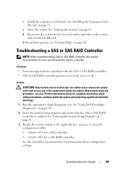
... the controller's documentation for complete information about configuration settings. See "Using Dell PowerEdge Diagnostics" on page 70. Action CAUTION: Only trained service technicians are authorized to the electrical outlet, and turn on page 205. i Install the expansion card shroud. See "Closing the System" on page 193. 2 Enter the System Setup program and ensure that the SAS or SAS RAID controller is enabled. k Reconnect the system to remove the system cover and access...
... the controller's documentation for complete information about configuration settings. See "Using Dell PowerEdge Diagnostics" on page 70. Action CAUTION: Only trained service technicians are authorized to the electrical outlet, and turn on page 205. i Install the expansion card shroud. See "Closing the System" on page 193. 2 Enter the System Setup program and ensure that the SAS or SAS RAID controller is enabled. k Reconnect the system to remove the system cover and access...

Hardware Owner's Manual (PDF)
Page 193
..., run PowerEdge Diagnostics for systems running supported Microsoft® Windows® and Linux operating systems are available at support.dell.com and on chassis and storage components such as hard drives, physical memory, communications and printer ports, NICs, CMOS, and more. If you are unable to help messages that briefly describe each test and its parameters. For information about using the PowerEdge Diagnostics, then use the system diagnostics. Running the System Diagnostics 193 The files required to test your system's hardware...
..., run PowerEdge Diagnostics for systems running supported Microsoft® Windows® and Linux operating systems are available at support.dell.com and on chassis and storage components such as hard drives, physical memory, communications and printer ports, NICs, CMOS, and more. If you are unable to help messages that briefly describe each test and its parameters. For information about using the PowerEdge Diagnostics, then use the system diagnostics. Running the System Diagnostics 193 The files required to test your system's hardware...
Hardware Owner's Manual (PDF)
Page 220
... Windows Powered operating system is expressed as the number of pixels across by the number of XML Web services. A video adapter may be an expansion card that allow data to display at a specific graphics resolution, you start -up and down. Video drivers may be integrated into an expansion slot. Most VGA and SVGA video adapters include memory chips in addition to match the video adapter installed in XML that plugs into the system board or...
... Windows Powered operating system is expressed as the number of pixels across by the number of XML Web services. A video adapter may be an expansion card that allow data to display at a specific graphics resolution, you start -up and down. Video drivers may be integrated into an expansion slot. Most VGA and SVGA video adapters include memory chips in addition to match the video adapter installed in XML that plugs into the system board or...

Hardware Owner's Manual (PDF)
Page 226
... NICs connectors, 15 troubleshooting, 167 O opening the system, 68 P password disabling, 203 setup, 59 system, 56 phone numbers, 205 POST accessing system features, 12 power indicators, 17 power supplies indicators, 17 removing, 76 replacing, 77 power supply installing, 81 removing, 78 replacing, 81 troubleshooting, 171 PowerNow!, 49 processor installing, 136 removing, 133 troubleshooting, 189 upgrades, 133 R RAC card installing, 119 removing, 117 RAID battery installing, 115 removing, 116 recommended tools, 64 removing 3.5-inch drive, 91 CD/DVD drive, 97 chassis intrusion switch, 141 control...
... NICs connectors, 15 troubleshooting, 167 O opening the system, 68 P password disabling, 203 setup, 59 system, 56 phone numbers, 205 POST accessing system features, 12 power indicators, 17 power supplies indicators, 17 removing, 76 replacing, 77 power supply installing, 81 removing, 78 replacing, 81 troubleshooting, 171 PowerNow!, 49 processor installing, 136 removing, 133 troubleshooting, 189 upgrades, 133 R RAC card installing, 119 removing, 117 RAID battery installing, 115 removing, 116 recommended tools, 64 removing 3.5-inch drive, 91 CD/DVD drive, 97 chassis intrusion switch, 141 control...


